Fender Design Challenge
FENDER
OBJECTIVES:
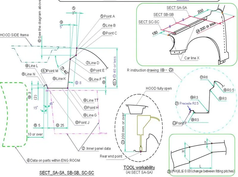
Creating mounts for the front fender with gives styling surface and master sections.
MASTER SECTION
Introduction:
Fender is a front outer side member of a car which covers the wheel side. Fender purpose is to prevent sand, mud,rocks,liquids and other particles. The major role of the Fender is to avoid the chipping inside the engine compartment. During the motion the wheel picks a sand mud and small stone particle and throws it inside the car and these fenders will be helpful in preventing them by hitting inside the engine compartment and car body. These fenders will have a plastic part which lies on wheel arch area. The fenders plays a major role to avoid problems for pedestrian also. Fender are typically rigid and can be damaged by contact with the road surface. It is often alspo called as mudgaurd.

Depending on the make of the car, Fenders may be made from fiberglass,steel,or other materials. Many of the these materials are designed to crumble in a crash, distributing the impact across the frame of the car to make the crash more survivable for the occupants of the vehicle.
The Fenders serve one main purpose to prevent the tires from spreading dirt,mud,little stones and other road debris. Without the fenders, a small stone could easily be thrown back at another car and crack its windshield. And your car will get completely messy from all the road spray.
FENDER LINER
It is not recommended to drive a vehicle without a fender liner (unless you are heading to a mechanic to install a new one ). A fender liner is an important part of your vehicle that serves as both a buffer and barrier between your cars engine,hood, radiator, headlight, and windshield.
FUNCTIONS OF FENDER:
- Car Fender limits the exposure of your body and engine to external element that are harmful.
- It provides safety to the driver and passengers at the time of accidents or collisions. They are manufactured in a way to provide bend during front and side collisions.
- Fenders flares are attached to ensure that both the body and engine have minimal contact with corrosive elements.
- It helps to avoid wind resistance and make your car more aerodynamic.
- Car fenders enhance the overall look of your car. Fender flares are available in distinctive designs in the market. Mostely you find universal fender flares, but you can get customized cars fenders to fit your car wheels.
Types of Fenders
In respect to design, two types of fender are there
- Full Bumper type
- Half Bumper type
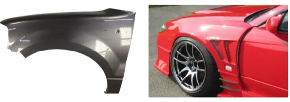
fig1: Full Bumper Type
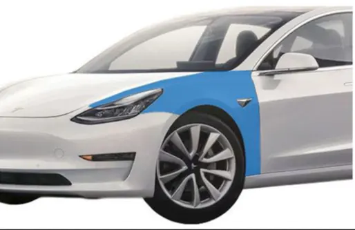
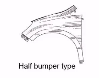
fig2: Half Bumper Type
DESIGN CONSIDERATION
Design or important the fender skin data for designing mountings over it.
1. DRIP MOUNTING AREA:
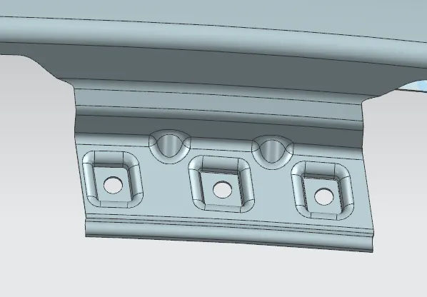
Firstly, the basic design of a fender involves in developing the drip area as it is a major mounting region and requires certain considerations to meet the standard values. This design is worthable region of the fender in car.
- It is the area through which the Fender is attached to engine housing through fastners.
- There should be some consideration followed to design the drip area, from back side of the fender there should be 200mm clearance .
- For cowl munting area and from the front there should be 150mm clearance for the head lamp housing unit.
- Embosses are provided to increase strength, corners of the flanges are smoothen to ease of the production
- Uniform wall thickness of 0.75mm .
2. A-PILLER MOUNTING AREA:
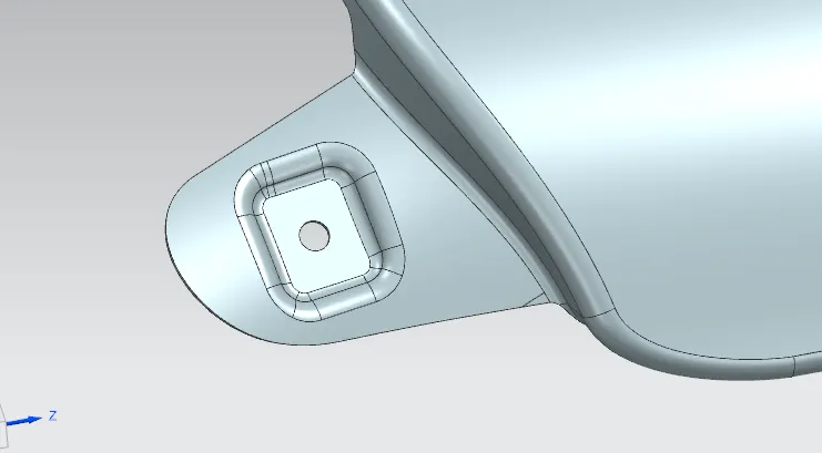
It is the A- piller mounting region, It will fixing on the front door wall. Through this mounting fender is connected with A-Piller of the car. Here also embossin needed for fastners.
3. BUMPER MOUNTING AREA:
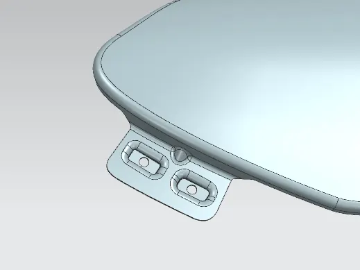
In this region car bumper mounted with fender part. In the collision a large amount of force will be transferred through this mounting region.so it have that much rigidity. The dart and embosses are creating for more strength of the mounting region. It will also reduce the spring back effect.
4. BAFFLE MOUNTING AREA:
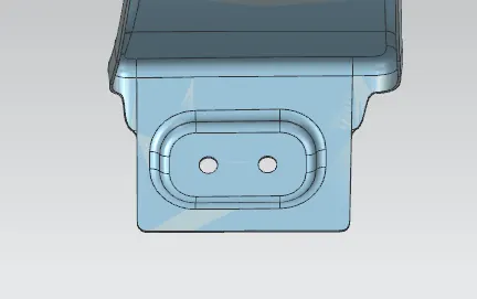
In this wheel arch section plastic baffle mounted with fender part. No embosses are needed this area because baffle mounting fastener with push pins. so pin holes are created there without emboss.

5. SILL MOUNTING AREA:
In this area car door sill part mounted with fender. Here proper embossing is needed for fastner mounting area.
INDICATOR AREA:
We have added a indicator here.
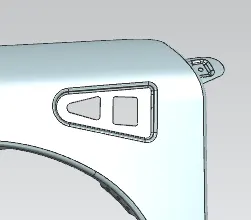
FIG: TURN SIGNAL LIGHT MOUNTING AREA
DESIGN PARAMETERS:
1.Curve on Surface
In this command tool using creating curve on the fender skin surface in required shape.
2. Bridge curve
In this command tool using the sharp corners are removing the all regions.
3. Dart Legacy
In this command tool using the two faces joined the rigidity of the material. It is also special command in nx cad.
4. Emboss
In this command used for the strength of the material is designed.
5. Edge blend
In this command used for any tool chipping on the material will get unbroken. It is also sharp corner repaired.
6. Law extension
In this command used for the sheet will extended and reduced in required length and angle.
MANUFACTURING PROCESS:
The car fender is based on injection molding process opimization that aims to resolve the trade-off between energy consumption and product quality at the same time in which process parameters are optimized variables. The process is specially optimized by applying response surface methodology.
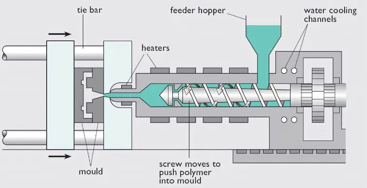
The basic injection molding process
- The mold closes
- Injection
- Cooling
- plasticizing the resin
- Ejection
- Removing the runner and packaging.
STEP1: THE MOLD CLOSES
The injection molding cycle timer begins when the mold is closes. In some cases, as with the use of robots, th cycle runs "part to part" which means the cycle begins and ends when the robot recieves a new part touches the conveyor belt.
STEP2: INJECTION
The heated plastic is injected into the mold.
STEP3:COOLING
Once the mold is filled the part is allowed to cool for the exact amount of time needed to harden the material.
STEP 4: PLASTICIZING THE RESIN
While the part cools, the barrel screw retracts and draws new plastic resin into the barrel from the material hopper.
STEP 5:EJECTION
The mold opens and the ejector rod moves the ejector pins forward. The part falls and is captured in a bin located below the mold.
STEP 6:REMOVING THE RUNNER AND PACKAGING
Although the injection molding machines cycle ends on step5 the process continues. Periodically the machine operators or robots seperate the usable parts from the left over runner. Molds with hot runner systems may not have runner or waste because the pathway is maintained at a constant heat.
CONCLUSION
At the end, front fender is Designed from the master section provided with Drip mounting, A-Piller,Sill, Bumper, and Splash or Baffle mountings using NX as CAD tool.