Wiring harness design in CATIA V5 - 3D modeling Week 2 Challenge
AIM
given data
- Deutsch DT06 – 08SA ( https://www.te.com/usa-en/product-DT06-08SA.html)
- Tyco 174357-2 (https://www.te.com/usa-en/product-2-174357-2.html?source=header-match)
- Tyco 85229-1 – (https://www.te.com/usa-en/product-85229-1.html?q=85229&source=header)
to consider various factor to define connection point
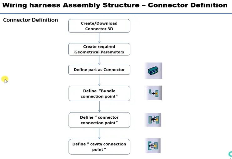
to create the connection point and bundle connection point
Deutsch DT06 – 08SA
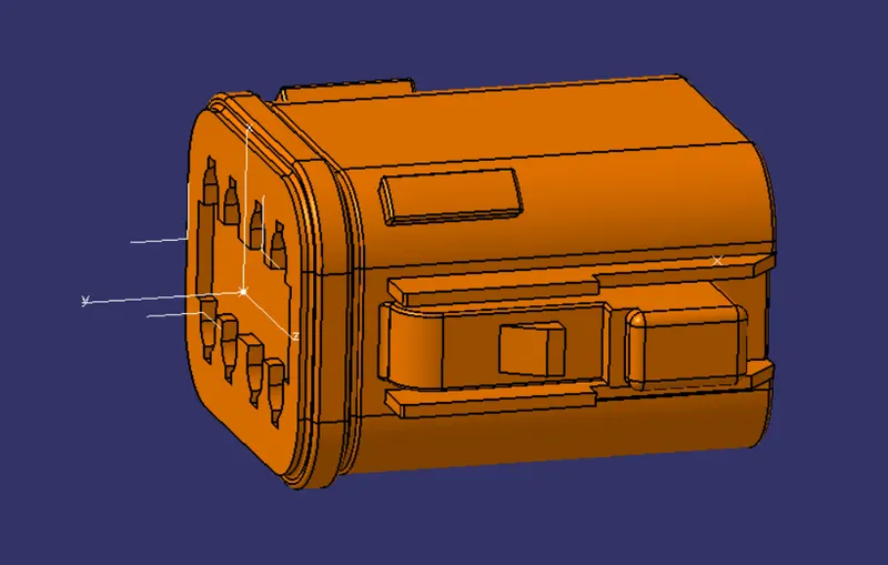
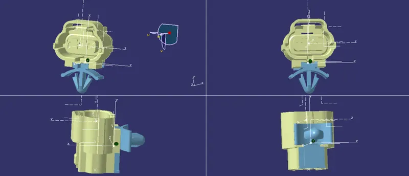
create Axis System with respect to the point which we have created and defining the axis direction .
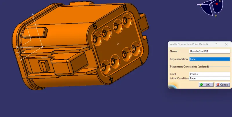
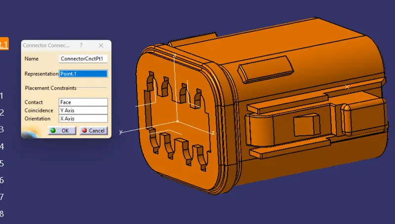
Tyco 85229-1
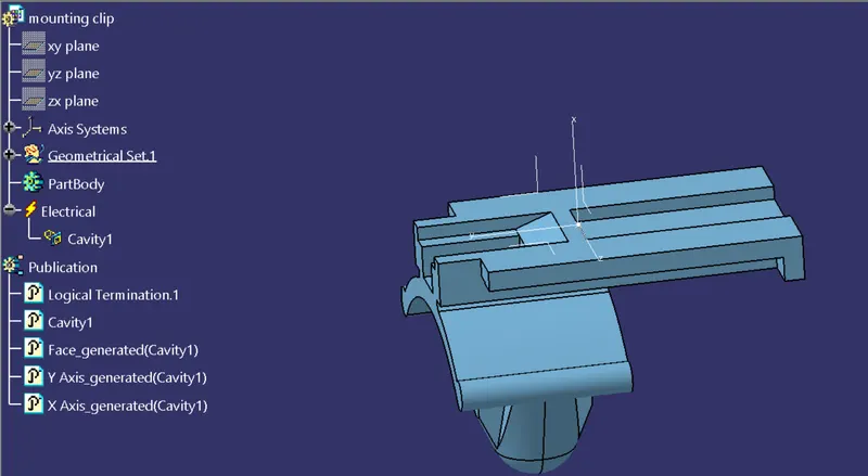
Tyco 174357-2
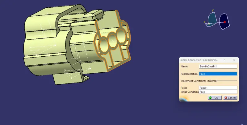
- THE CONNECTOR IS FIRST UPLOADED IN THE PART DESIGN WORKBENCH
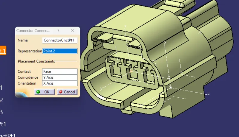
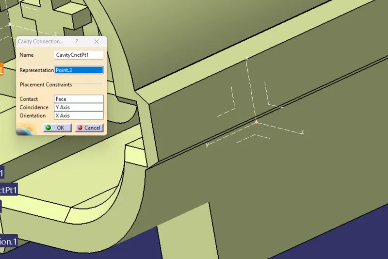
- WE DEFINE THE POINTS FOR CONNECTOR CONNECTION AND BUNDLE CONNECTION.
- THE AXIS SYSTEMS ARE PLACED ON THE CONNECTOR CONNECTION AND CAVITY CONNECTION POINTS
- THE ORIENTATION OF THE AXIS SYSTEM IS NOT SPECIFIC, WE JUST NEED TO FOLLOW A SIMILAR ORIENTATION FOR ALL THE PARTS.
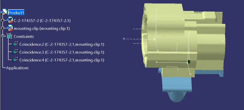
- HERE THE Y-AXIS IS IN THE DIRECTION OF THE CONNECTION, Z-AXIS ALONG WITH THE CLIP MOUNTING AND X-AXIS ALONG BOTTOM TO TOP.
conclusion
To finish the given part as per the electrical configuration.