Wiring harness design in CATIA V5 - 3D modeling Week 2 Challenge
WIRING HARNESS DESIGN 3D MODELLING
In the initial course work we have studied about the design of automotive interior trims as well as exterior trims. We are all familiar with the Catia V5 software. Here we have started the new course work of automotive wiring harness using Catia V5.
What is wiring harness?
- Wiring harness is nothing but an assembly of different cables, wires, subassemblies wires, which are used to transmit the electrical signals from one end of the system to the other end.
- In automotive sector this wiring harness plays an important role and is used in more than one place inside automotive, like the head lights, the sensors, to supply current to sparkplug, tail lamps and many more.
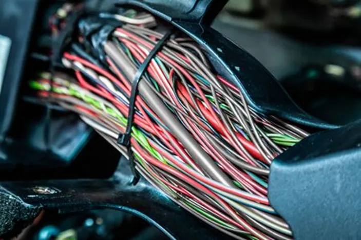
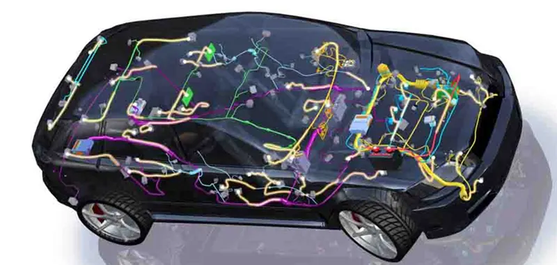
The wiring harness consists of the various terms used in assembly like:-
- Wires
- Connectors
- Terminals
- Protection coverings
- Insulations
- Clips and clamps
- Guiding channels
- Retention devices
So this are all the terminologies used in the wire harness design.
So based on this we are provided with the challenge, and it is expected from us to initially study the connector and connector clip data and then define those as the electrical connector using the electrical part design workbench. The reason we need to define as the electrical component is because the CAD software consider every part in it as the CAD model.
So till now in Catia V5 we were using the generative shape design for the automotive interiors trims. But now as we working on to the wire harness design, here we need to switch or workbench from generative shape design to the electrical harness discipline workbench as shown in the figure below.
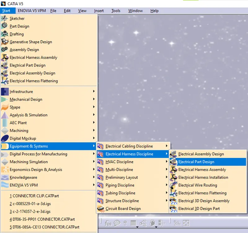
Here we don’t need to design the actual component using the sketcher workbench. The components are given as an input we need to define the geometry and then define the part as an electrical component.
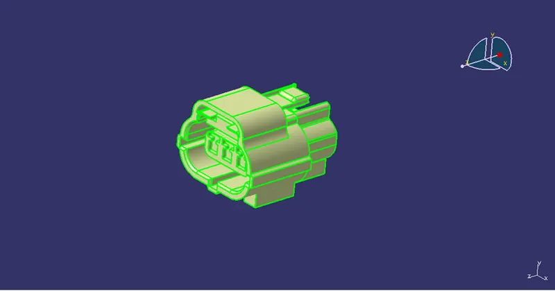
Here we are provided with the connector and the connector clip as shown in the figure below.
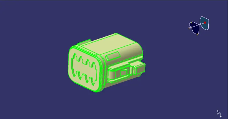
Connector 1
Connector 2
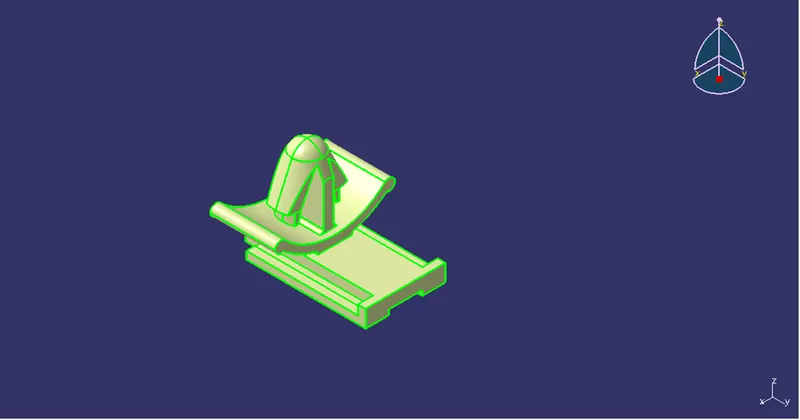
Connector clip
So this are all the inputs we are provided. We need to define the geometry and then define the electrical connector using electrical part workbench.
So let’s start with the first connector:-
The first connector is shown in the figure below:-
Here initially using the part design workbench the center points are plotted on to the connector connection side as well as the bundle connection side.
The connector connection point are the points on the connector from where the other connector is connected.
And the bundle connection point is the point from where the wires are attached to the connector.
So here initially the points are plotted along with the axis system. Here the y axis should be normal to the connector connection point and x axis should be in the direction of locking mechanism as shown in the figure below.
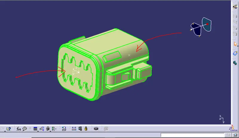
As we can see the points are plotted now here we need to switch the workbench from part design to the electrical part design and then define the above part as the connector as shown in the figure below.
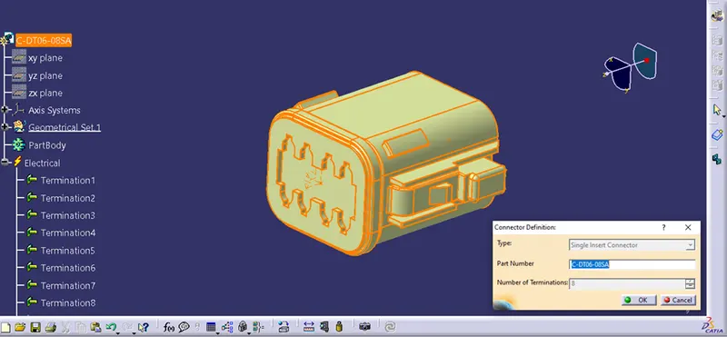
While defining the connector we need to give the count for the no of terminals i.e the no of the wire holes present at the backward direction.
And then bundle connection points are defined as shown in the figure below.
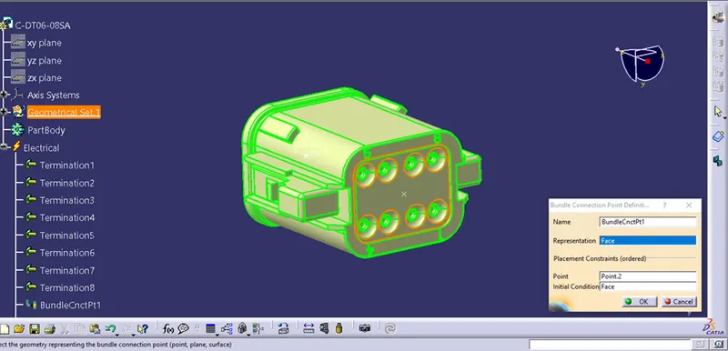
Here the representation is selected as the face of the bundle connection point and the point is selected as the centre point.
And then finally the connector connection points are defined as shown in the figure below.
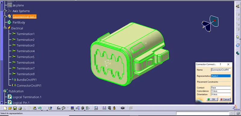
Hence we have defined the first component as the electrical connector.
Similarly in the next model firstly the geometry is defined using the part workbench and then the component is defined as the electrical connector using the electrical part design workbench as shown in the figure below.
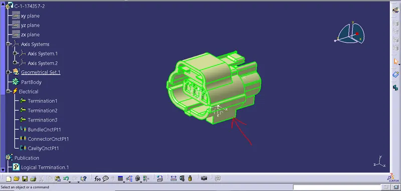
But here the difference is at the bottom one cavity connection point is defined using the same geometry define method, for the mounting of the connector clip as shown in the figure below.
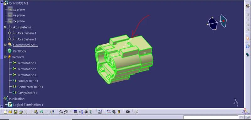
The one highlighted point and the axis is the cavity connection point shown in the figure above.
Now the final component is the connector clip as shown in the below figure.
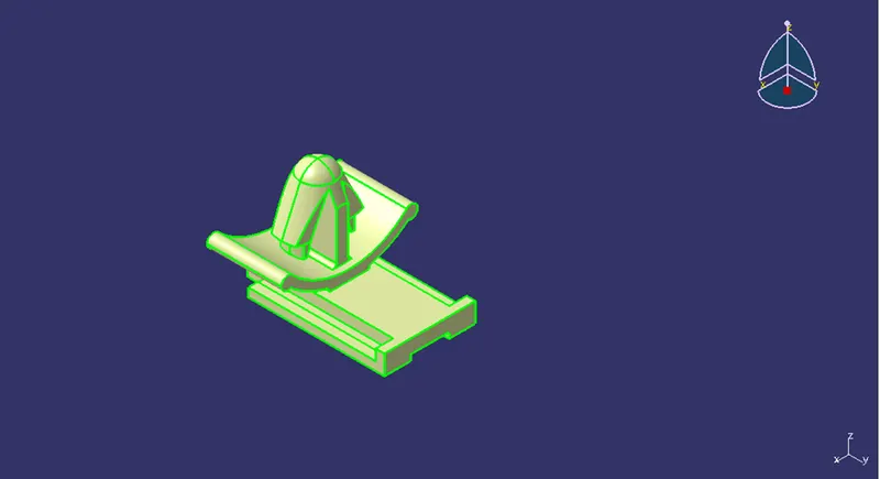
Here this component is initially defined with the geometrical points and the axis system as shown in the figure below.
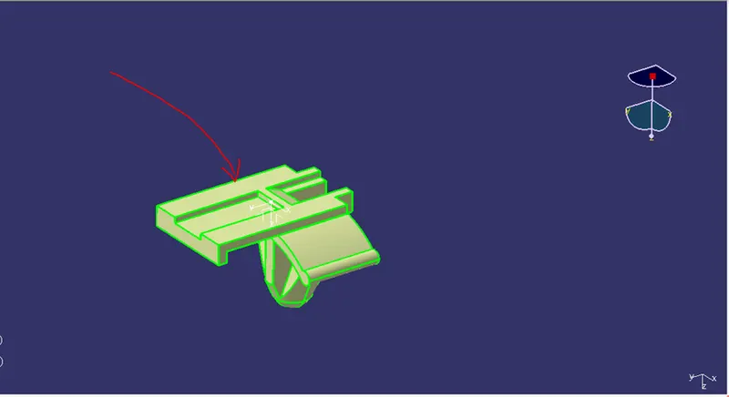
Axis system and the point.
Now here this component is the connector clip not the connector, so here the component is initially is defined as the equipment in the electrical work bench and then the cavity point is defined as shown in the figure below.
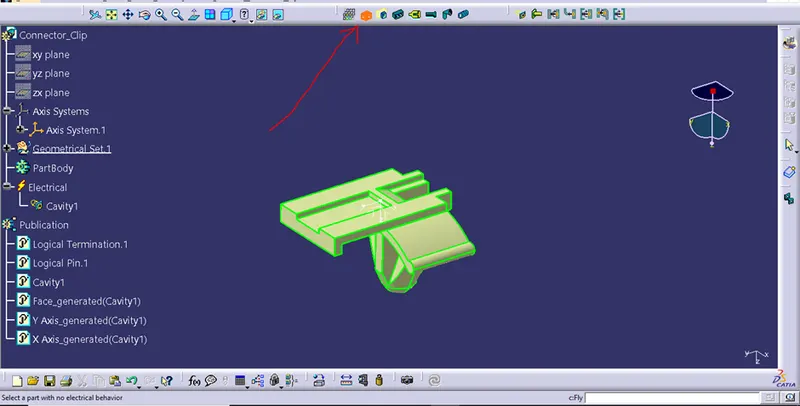
The highlighted command is define equipment.
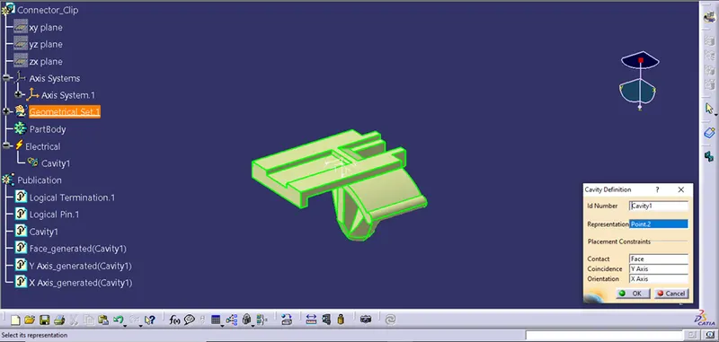
The component is defined as the cavity.
Here we have completed the defining of the electrical connectors and connector clips.
Now this both the connector and the connector clip is opened into the electrical assembly workbench and then they are connected using connect electrical devices command as shown in the figure below.
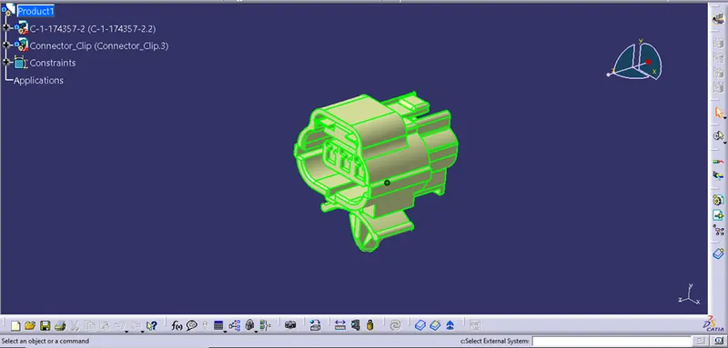
Hence our challenge is fully competed.