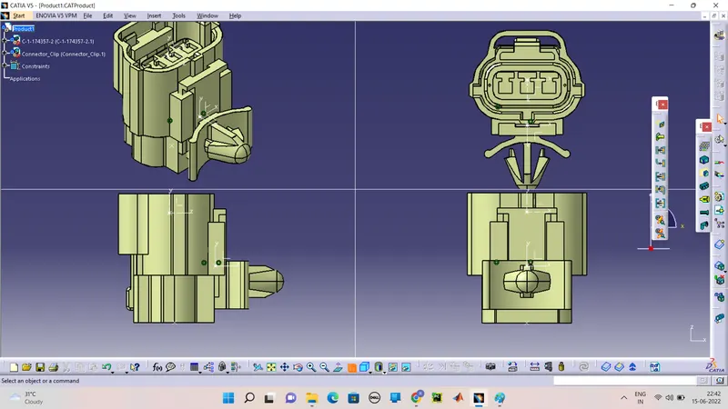
Wiring harness design in CATIA V5 - 3D modeling Week 2 Challenge
AIM:
To define the Electrical Connector and Clip as Electric component in the CATIA V5.
INTRODUCTION:
A wiring harness is an organized set of wires, terminals and connectors that run throughout the entire vehicle and transmit information and electric power, thereby playing a critical role in “connecting” a variety of components.
In the system to define the electric connector and clips by the catia v5 software and explain the process.
DESIGN PROCESS:
Be ready with the CATIA V5 software workbench and make the process requirement.
Download the connector in CAD model (isg format) and open with the catia software.
It is the geomentry model CAD design. From the "te.com" from the given link.
Ready to open with the CATIA V5 software by (FILES=>open "correct bath").
GEOMETRY PARAMETERS:
Firstly loaded CAD model make the piont on mating and bundle entry side. Andthen make the axis (Co-ordinate) system of the Connector connection point all in the Mechanicl Design in Part Design.
One things we want understand is Axis system was poistion or orientation of axis
1) X-Axis is orintation of locking mechanism.
2) y-Axis is normal to the another connector.
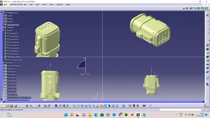
Define the Electrical connector in Electrical part design system. After declear electrical connector model turns to electric part identify by the wating tree structure. And pop up the dialog box.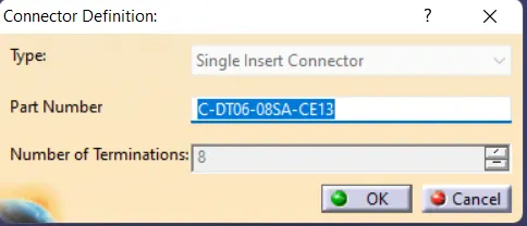
And define the number of terminals.
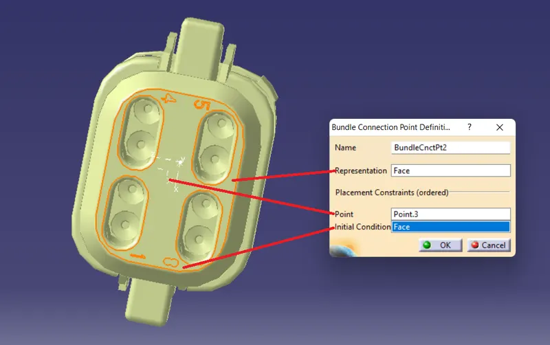
Define Bundle Connection point which is terminate wire should be inserted on this side(This point defines where the harness bundle segment point will end when routed to the electrical connector) even there is popup the dialoge box for creating Bundel connection point gives the asked perspectives.
Define Connector Connection point is mating side of connector (This point defines is used for the connection of one connector to another connector) even there is popup the dialoge box for creating Connector connection point gives the asked perspectives.
The complete Electrical Part as show.
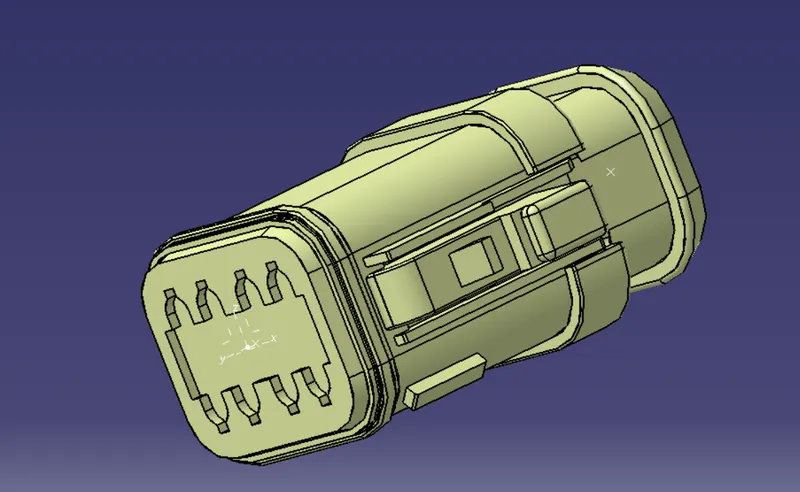
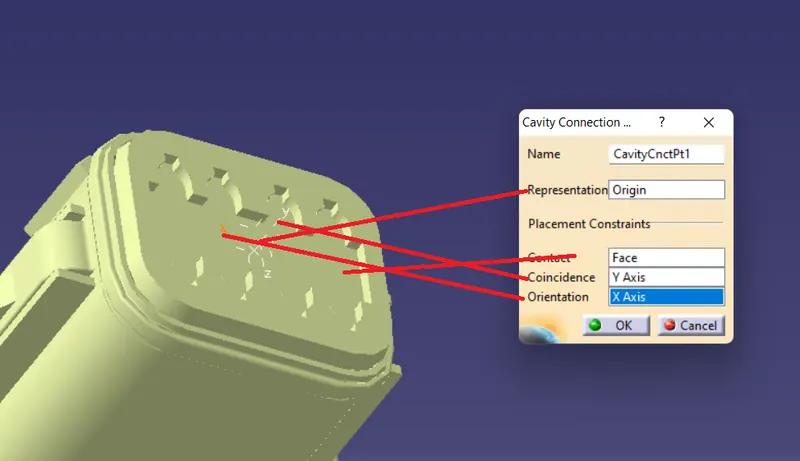
2) The process is same upto the connector connection point. Here is add the another one is Cavity connection point on the connector and create the referance for Connector Clip as well as.
Creatind Cavity connection point ask as per required details. With all the required points and definition.
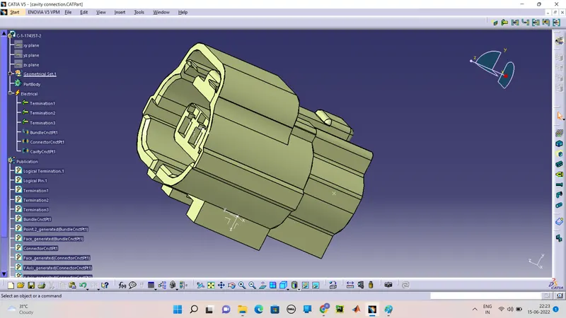
Define the Connector Clips from the geometry part points and Axis System andthen turns to the Electrical part design.
1) Define the equipment
2) Next to Define Cavity
After creating point and Axis next move to the Electrical Part Design.
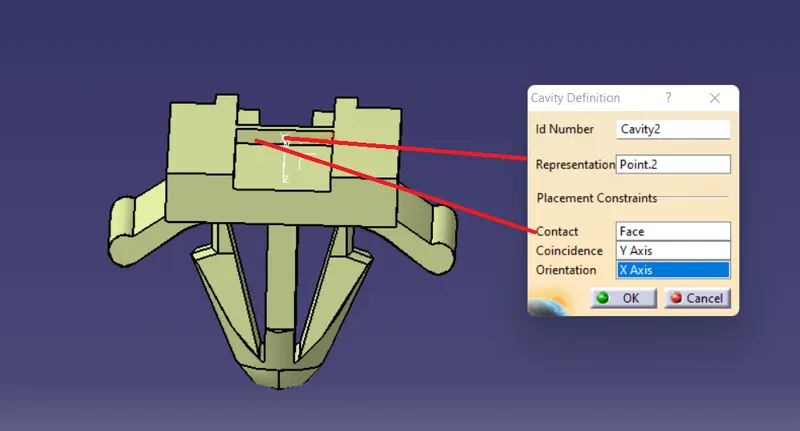
PRODUCT :
Make the individual parts as make sure to assemble by the Electrical Assembly Design and as wll as Assembly Part to create the product as the help of Manipulator tool and Connect Electrical Part respectively. The final product is