Wiring harness design in CATIA V5 - 3D modeling Week 2 Challenge
CONNECTOR DEFINATIONS IN CATIA V5
1. Deutsch DT06 – 08SA
Connector connection point:
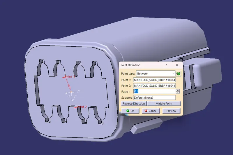
Create midpoint on the contact face which will be normal to wire bunddle .
Create Axis system
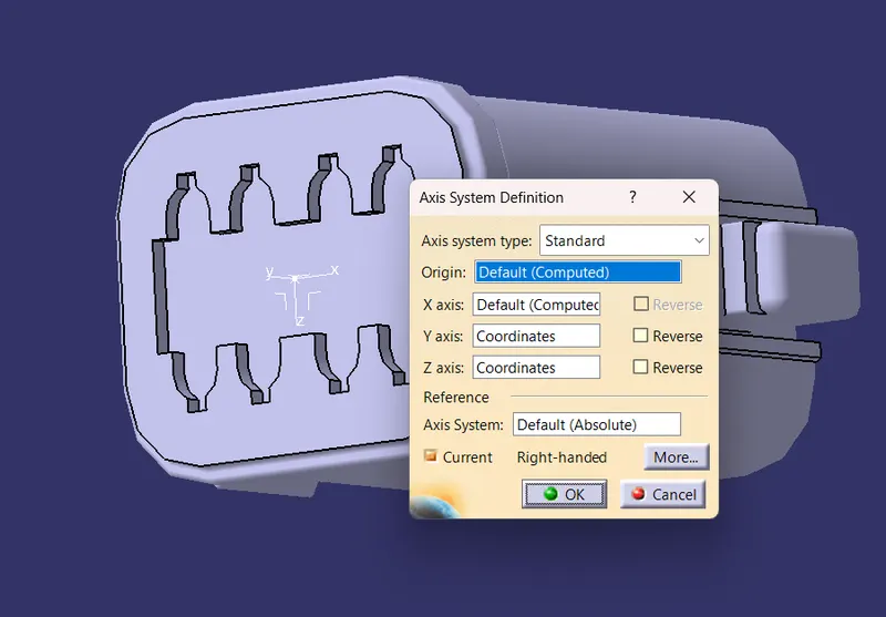
Make sure of the direction. The y axis is used as the mating axis. X axis is in the direction of locking.
NOW, switch to the electrical part design:
Define the part as our connector using the command:
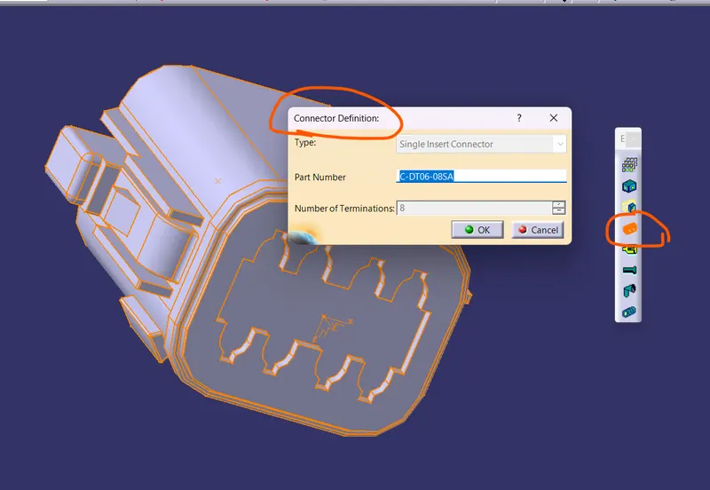
Fill the number of terminals in it. Our connector has 8 terminals.
Define the bundle connection point:
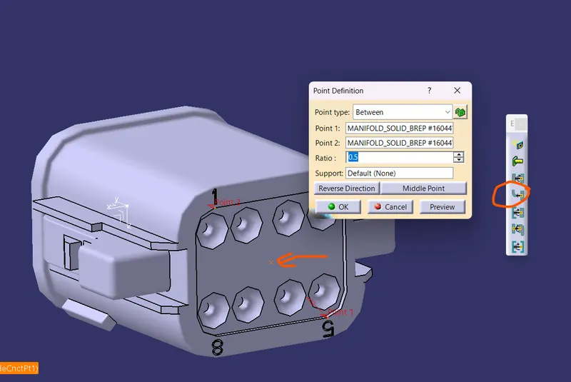
Define Connector connection point:
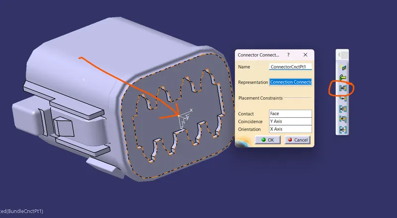
2.Tyco 174357-2 :
We will follow the same process as we did in the previous connection:
The steps are as follows:
- Create midpoint for the axis system
- create Connector connection point
- create Connector connection axis system
- create cavity connection point
- create cavity connection axis system
- Switch to Electric part design and define part as connector
- Define Connector connection point and cavity connection point
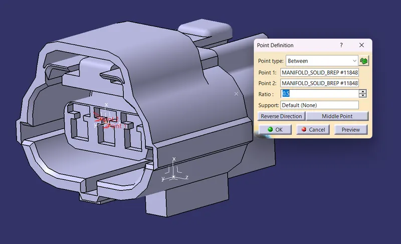
The midpoint for the connector connection point:
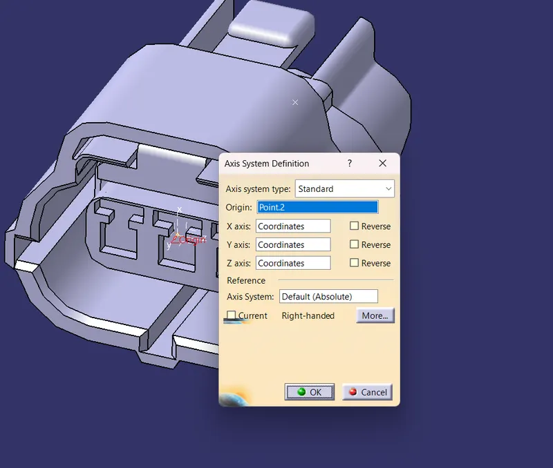
Create an Axis system on it:
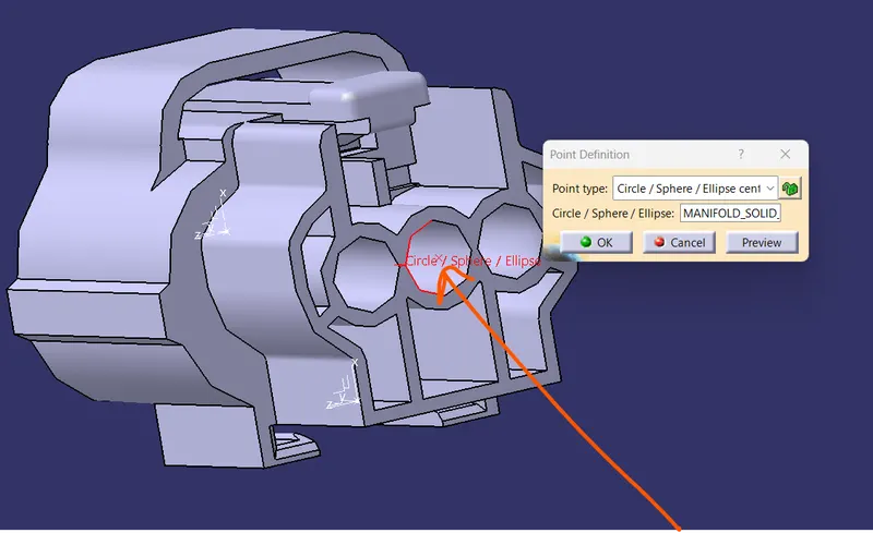
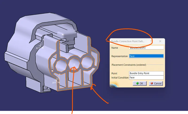
Now create a bundle entry point:
Now, we can switch to the electrical part design workbench:
Define the connector using command:
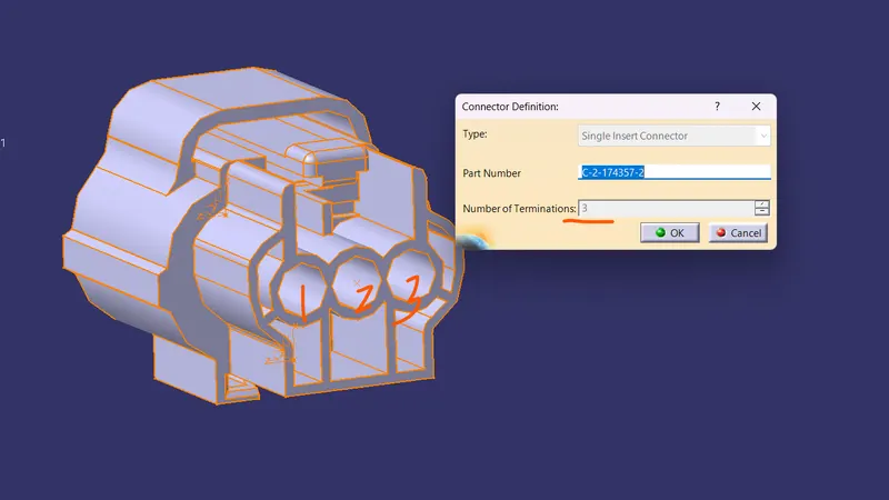
Count the number of terminals .
Now select the connector connection point along with the coincidence direction.
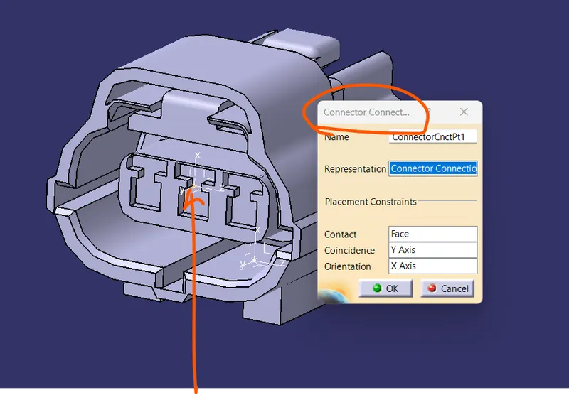
Select the Bundle connection point.
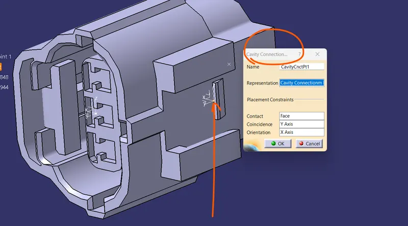
We have to attach a cavity in this part as well so Cavity connection as well.
3. Tyco 85229-1 –
We are following the same process here:
This part is a clamping unit so we have to provide a cavity unit only.
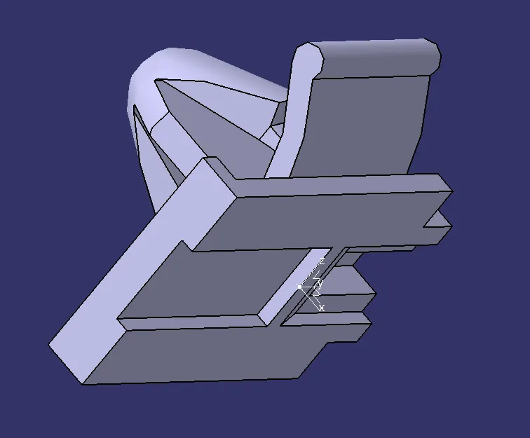
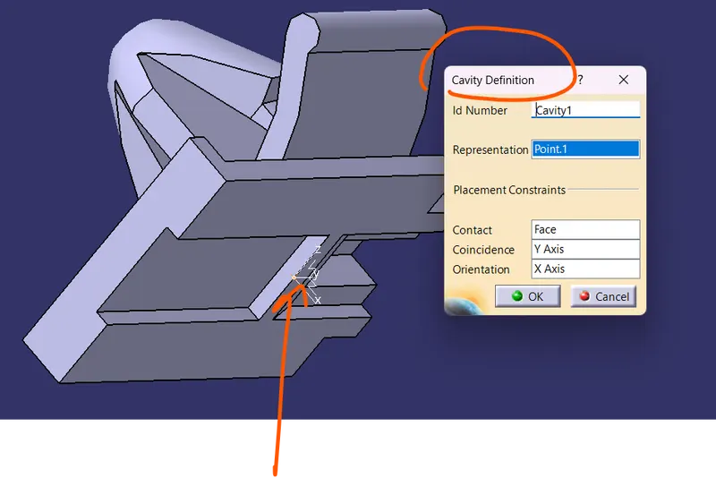
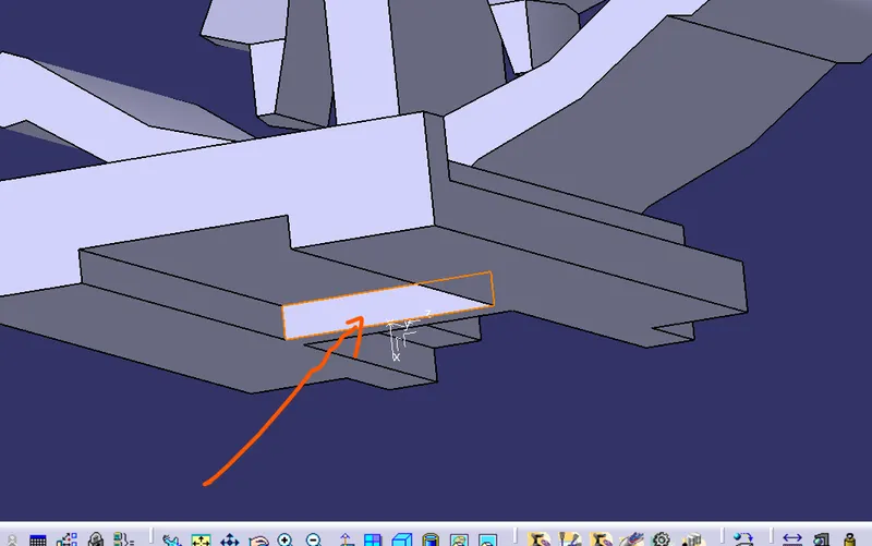
Since both parts could be assambles in a single geometry:
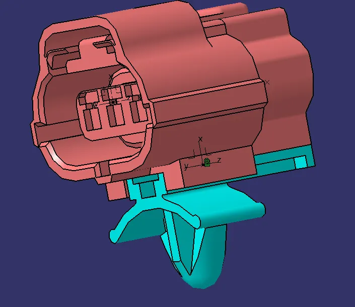
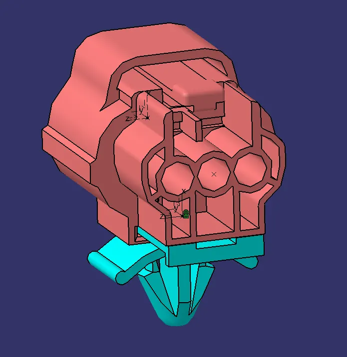
We have assambled both the part using the Electrical assamblt design.
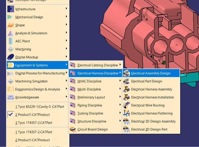
ALL THE PARTS AND ASSAMBLY PARTS ARE ATTACHED BELOW IN THE FILE: