Week 8 - Challenge 1 - Base Bracket Design
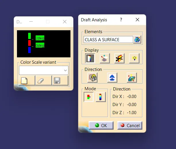
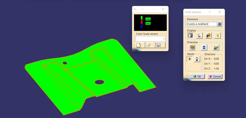
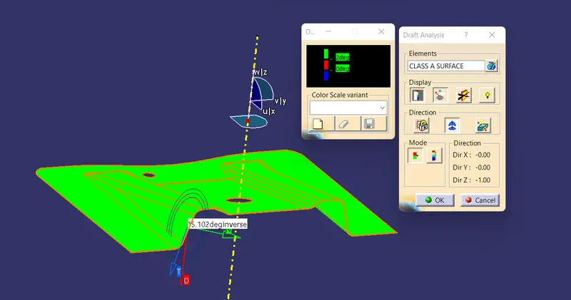
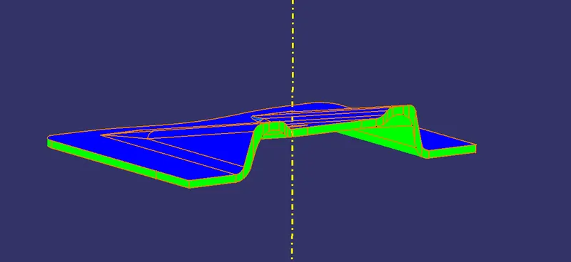
DRAFT ANALYSIS AND COLOUR SCALE FOR CLASS A SURFACE :
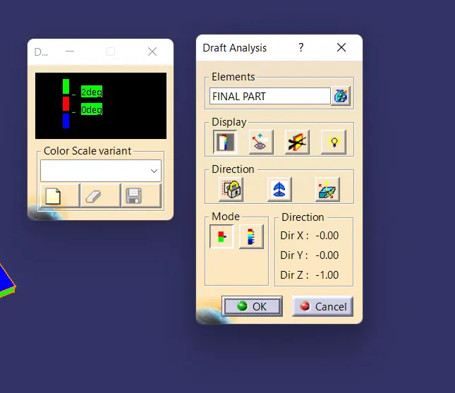
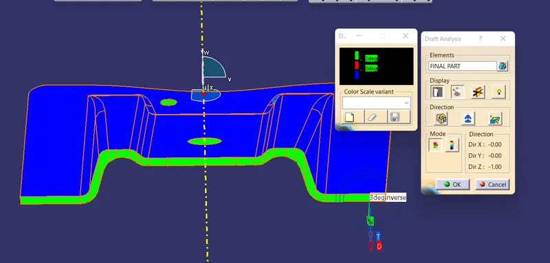
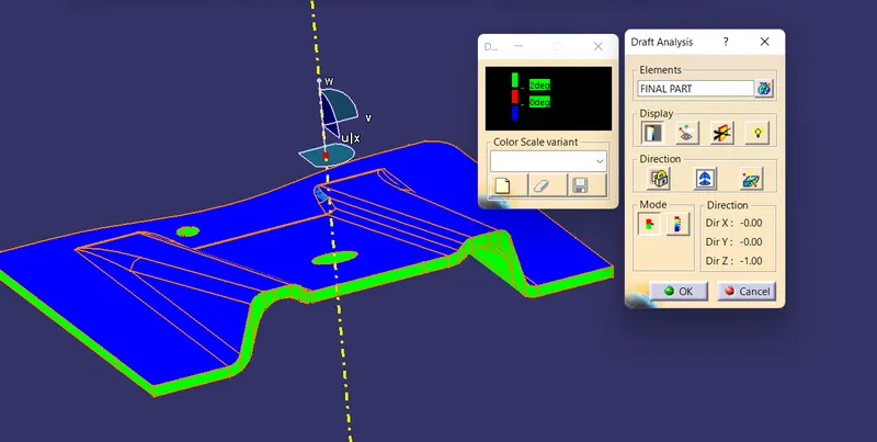
SCREENSHOT FOR DRAFT ANALYSIS AND COLOUR CODE FOR FINAL COMPONENT:
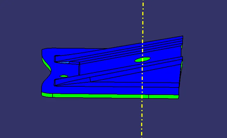
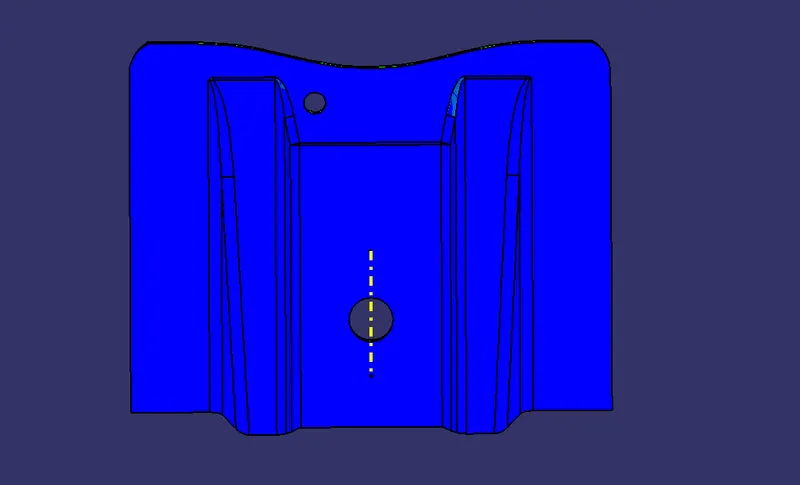
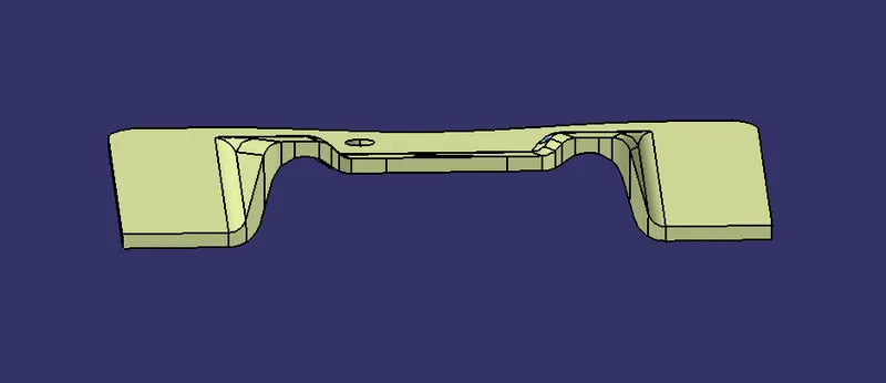
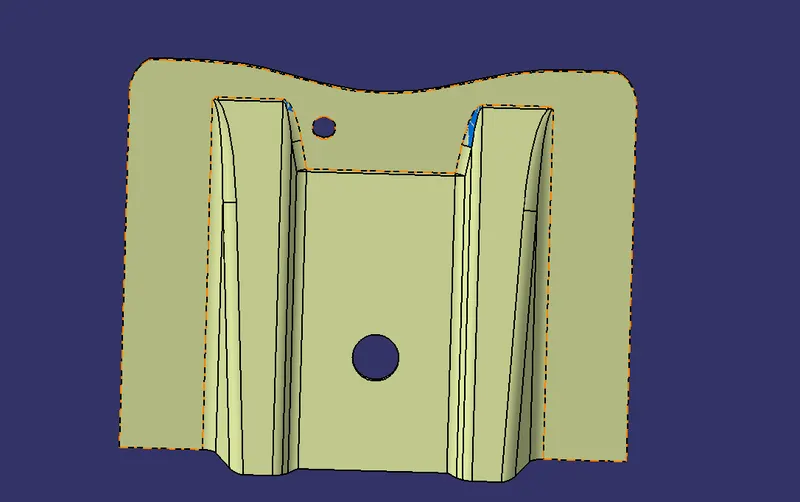
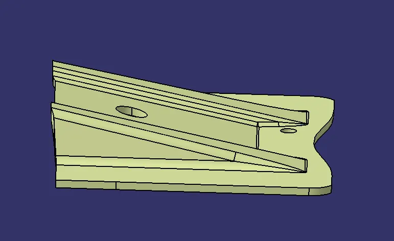
SCREENSHOTS OF THE SOLID MODEL:
PIBLICATIONS:
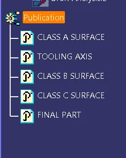
REPORT:
DRAFT ANALYSIS:
Draft analysis is doen for determining where the part you drafted will be easily removable through the core and cavity. It is performed on the basis of colour range. There is a range provided for each colour . According to which we can easily analyze the part we have to draft.
It can be accessed by using the "Insert" feature. Insert>Analysisi> Feature Draft Analysis.
By this feature you can measure any draft angel in your produst very easily. You can select the draft direction as well.
Tooling Axis:
This is the main tooling axis by reference to which we perform draft. Basiaclly it can be many points. In the part in the example above, it was a hole given on the A surface. We created an axis with the centre of that hole which directed the draft.
In here we used Bisecting method to create the tooling axis.
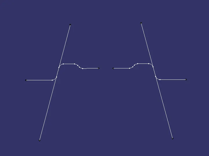
As in the screenshot, we created an intersect with the given A surface along with the z direction. We used both side profile to make lines both side. With those lines we used a feature called bisecting line.
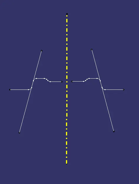
Thus, we got our tooling axis.