Week 9- Unsteady moving zones Approach
Aim: To simulate the motion of blades in a generic turbomachinery component using an unsteady approach.
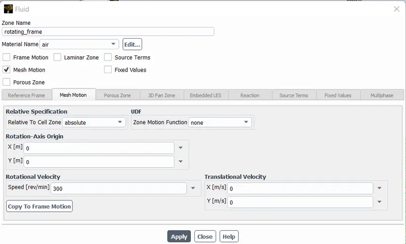
Assume blade rotation at 300rpm
Choose an appropriate time step for the simulation and generate an animation file for the rotation.
Theory:
Moving Mesh Approach :
Used for modelling unsteady phenomena such as;
- Vortex induced flows
- Interaction of vortex with bodies
In Moving Mesh Approach :
- Mesh is moving
- Mesh Topology changes with time
- Mesh quality changes
- Control volume changes with time
- Smoothing /layering /Remeshing can be done.
Procedure:
Set up:
- Import the given mesh file in fluent as shown below,

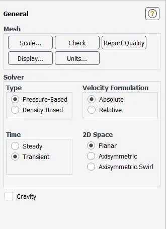
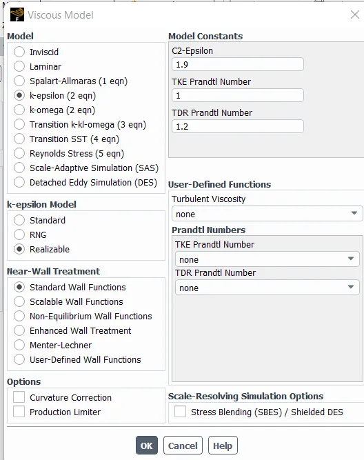
- Viscous Model :
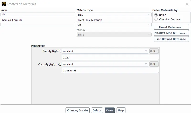
- Material:
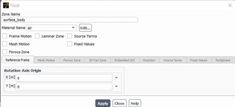
- Cell Zone Conditions :
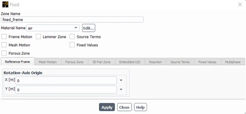
Blade rotation is 300 RPM
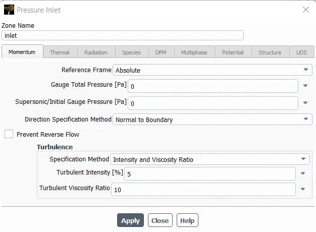
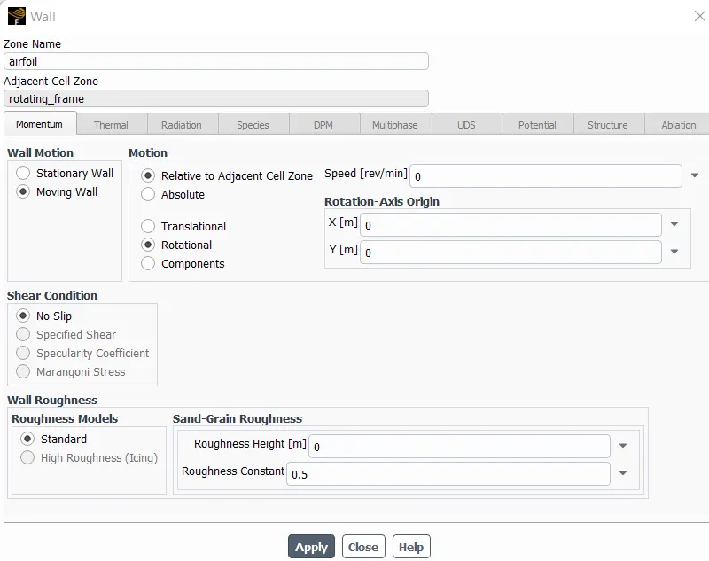
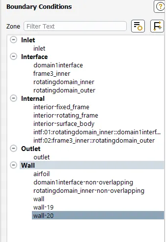
- Boundary Conditions :
- Inlet:
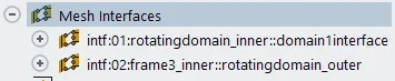
- Mesh Interfaces :
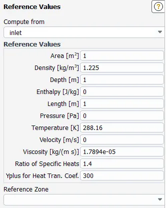
- Reference Values:
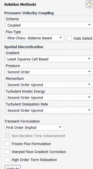
- Solution:
- Methods:
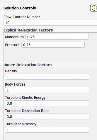
- Initialization:
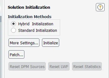
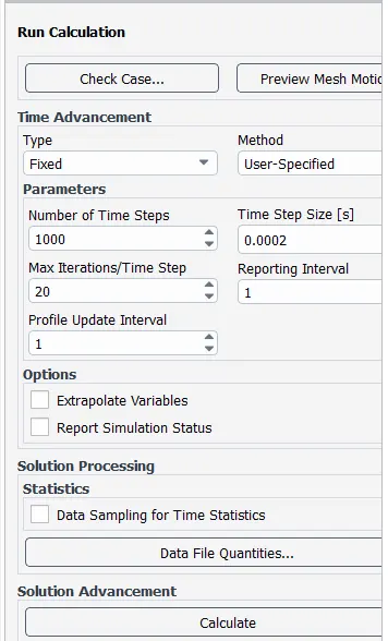
Rotation of blade(N)= 300 Rpm
To find the time period = T =60/N
i.e Time required for one complete revolution (T) =0.2 sec
So the Time step size=0.0002 sec
Number of time steps = 1000
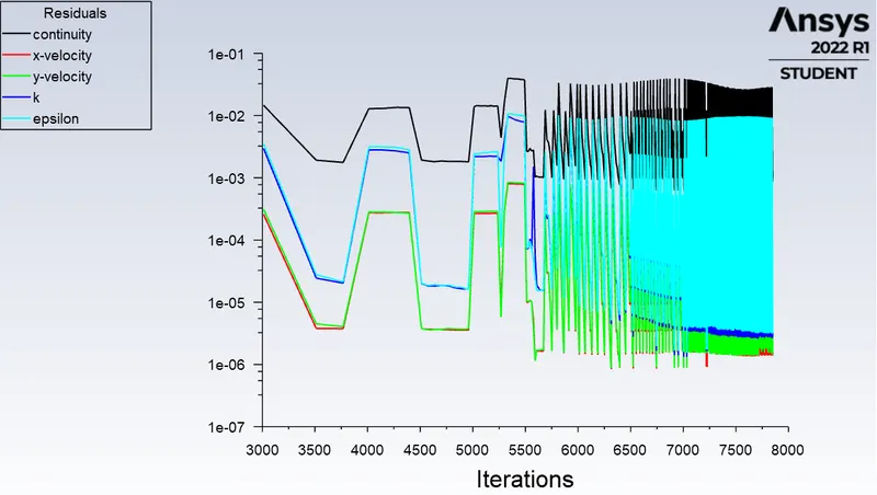
Results:
- Residual plot:
- Velocity Contour:
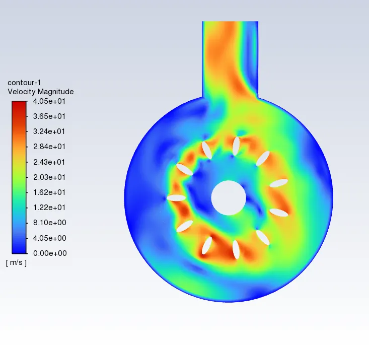
From velocity contour, we can say that the velocity near the airfoil and at outlet region is maximum and at wall of the surface body and in some region of fixed frame the velocity is minimum.
- Pressure Contour:
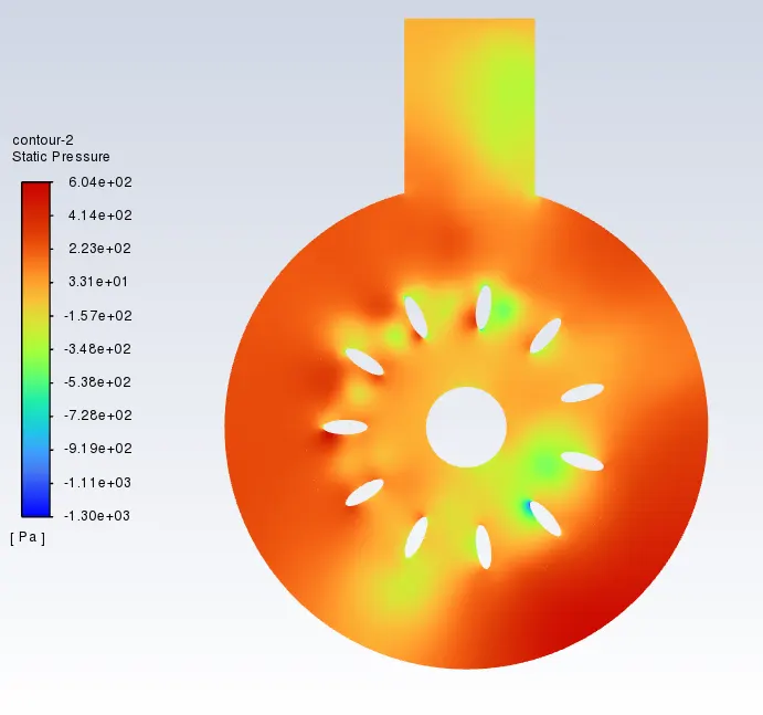
- Velocity Animation google Drive link:
https://drive.google.com/file/d/1xPMEiq0rY04atQzxkQU7Dq2fLGm88n6a/view?usp=share_link
- Pressure Animation google Drive link:
https://drive.google.com/file/d/1HSn1giQjpnQabWbV-6zIvPvyFTWmM0aK/view?usp=share_link
Conclusion:
- The simulation of the motion of blades in a generic turbomachinery component using an unsteady approach is done.