Week 9- Unsteady moving zones Approach
Unsteady moving zones Approach
Aim: To simulate flow using unsteady approach in turbomachinery.
Objetive: Simulate the motion of blades in a generic turbomachinery component using an unsteady approach.
Theory:
Three regions in the model:
1. Inner region -It is stationary, and acts as an intermediate region between the blades and the inlet.
2. Middle region - It undergoes rotational motion, and contains 10 airfoils placed 36 degrees apart from each other. The blades/airfoils will rotate at a speed of 300 rpm.
3. Outer region - It is stationary, and acts as a buffer region between the blades and the outlet. There is also an outlet tube for fluid to exit the domain.
Procedure:
Import the mesh file in Setup.
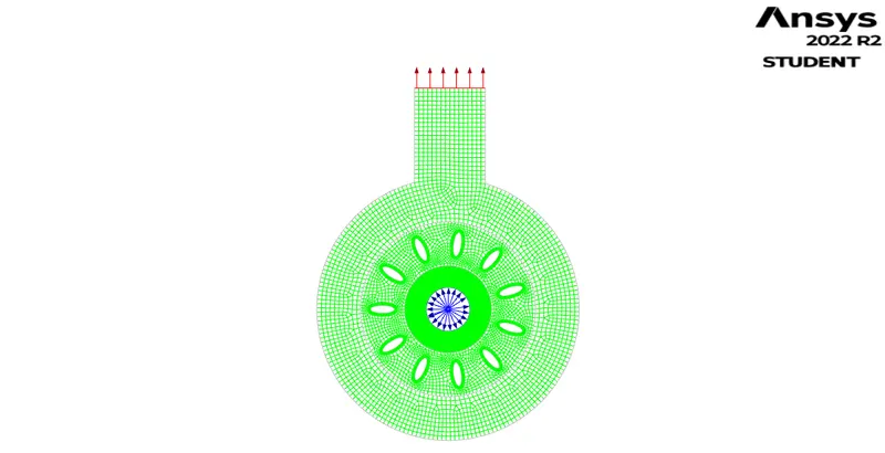
Moving frame approach
Solver:
Pressure based.
Steady state.
Viscous : Realizable K-epsilon.
Angular velocity - 300 rpm.
Pressure conotur:
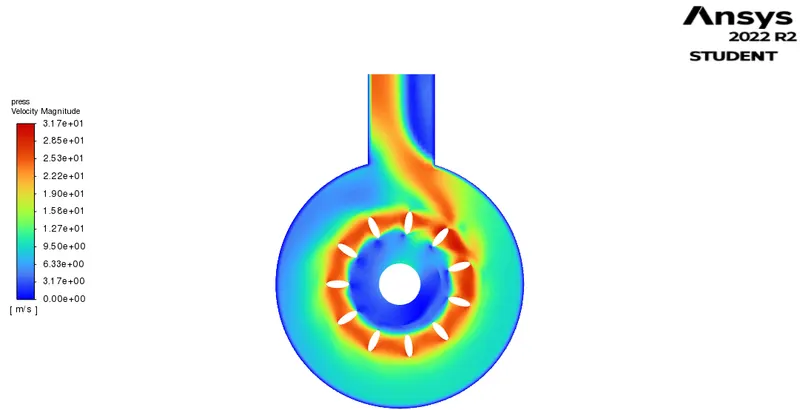
Velocity contour:
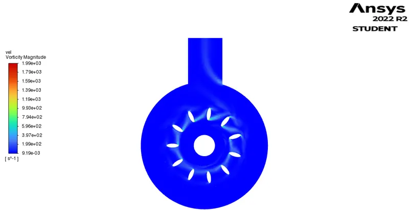
Vorticity:
Animation:
Moving mesh approach:
Transient state
Moving mesh - 300 rpm.
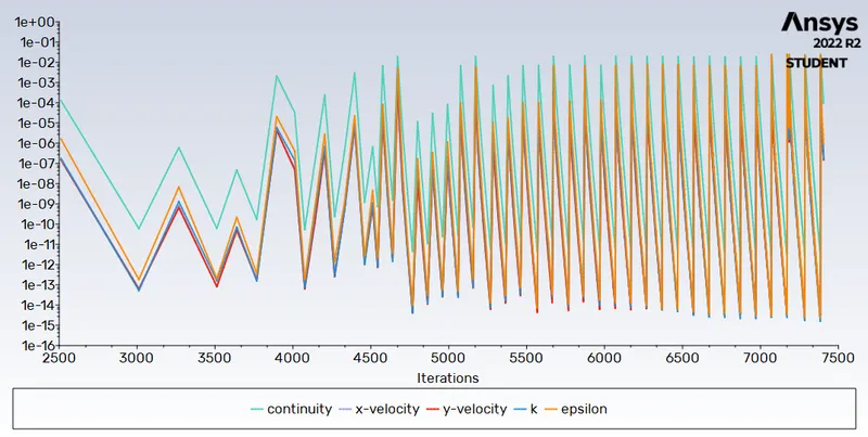
Residuals:
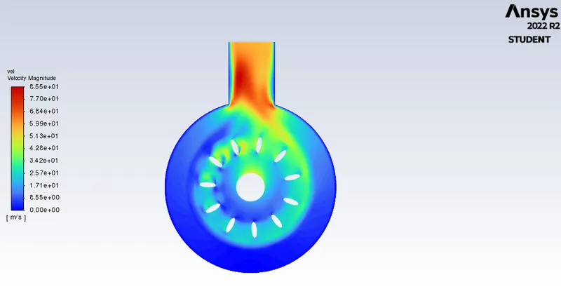
Velocity contour:
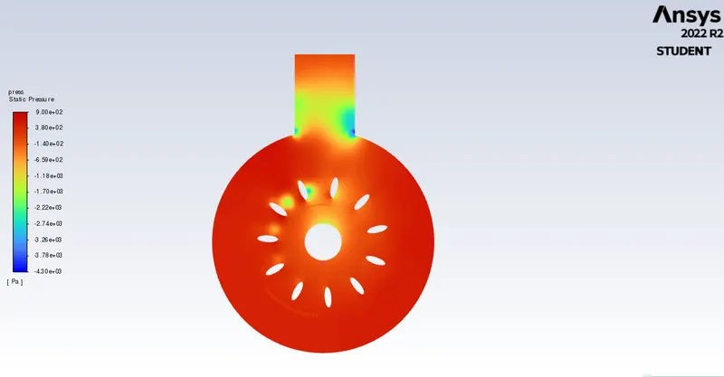
Pressure contour:
Animation :
Conlcusion:
The velocity is maximum at the tip of the airfoil and the velocity seperation happens at the edge of the aerofoil. The static pressure is less at the inlet and rises as it moves towards the tailing edges of the airfoil.