Tension and Torsion Test Using Ansys Workbench
TENSION AND TORSION TEST ANALYSIS USING ANSYS
OBJECTIVE
- To assign the steel 1006 explicit material to the specimen.
- To mesh the model.
- To apply the boundary condition.
- To collect the results and interpret.
PROCEDURE
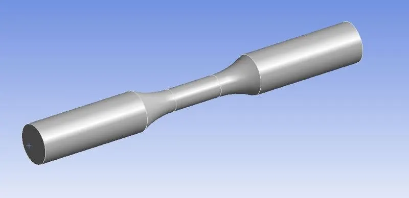
This simulation was an analysis of the tension and torsion test. The model can be seen in the figure below. The simulation seems to be explicit, therefore, it had to solve using the explicit dynamics module of Ansys.
 |
|
Figure 1: Specimen model in Ansys GUI. |
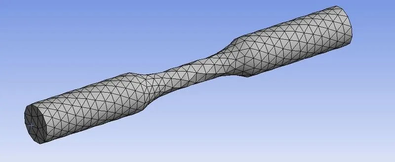
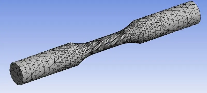
The Mesh section of the explicit dynamics module was opened. In that, the material of the specimen was set to steel 1006. Next, the mesh was created for the model, as shown in the figure below.
 |
|
Figure 2: Meshing of the specimen for tension test. |
 |
|
Figure 3: Meshing of the specimen for torsion test. |
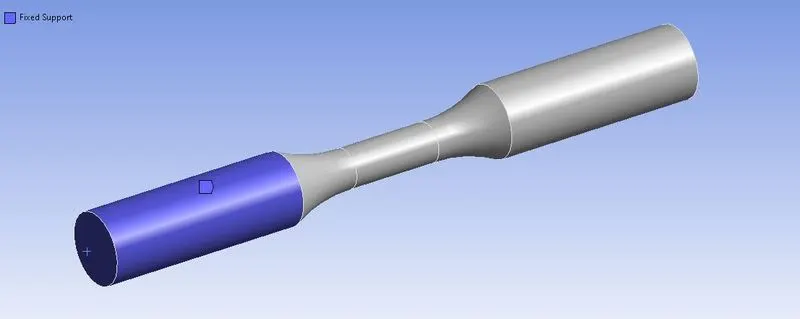
The end time of analysis was set to 0.001 s. In boundary conditions, one end of the specimen was fixed, as shown in the figure.
 |
|
Figure 4: One end of the specimen fixed using fixed support. |
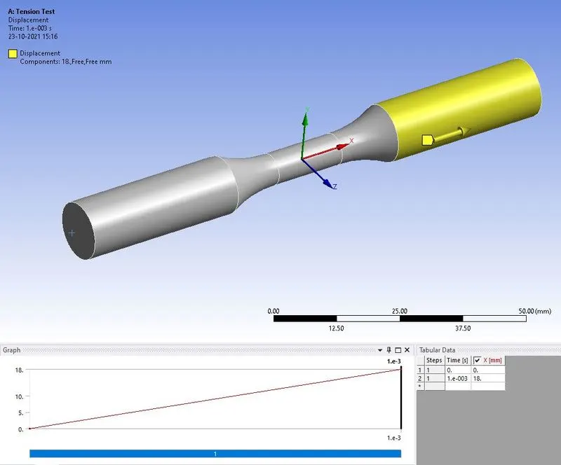
For the tensile test, a linear displacement of 18 mm was applied at the other end of the specimen, as shown in fig. 5.
 |
|
Figure 5: Linear displacement of 18 mm applied at the other end of the specimen. |
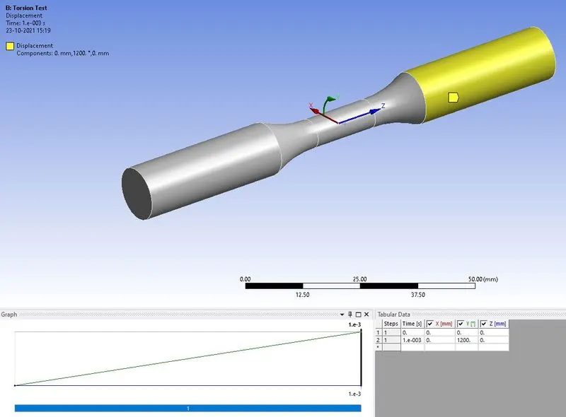
For the torsion test, a cylindrical coordinate system was created at the center of the specimen. Using this coordinate system, a displacement was applied at the other end of the specimen (in place of linear displacement, in tensile test).
 |
|
Figure 6: Rotation of 1200 degrees applied to the specimen, with one end fixed, using a cylindrical coordinate system. |
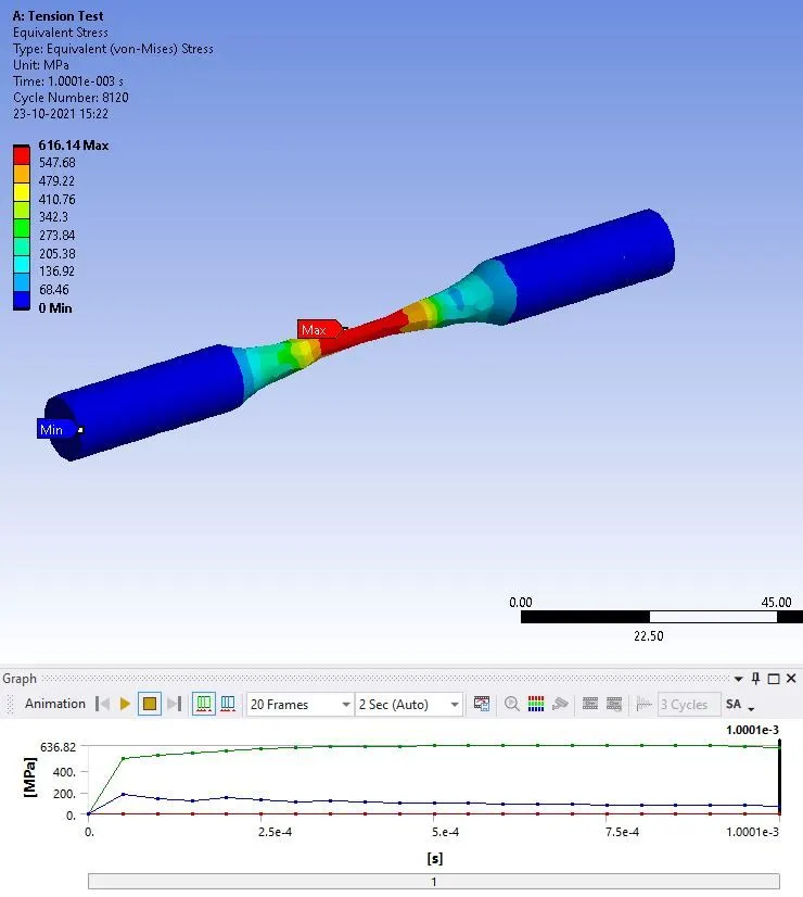
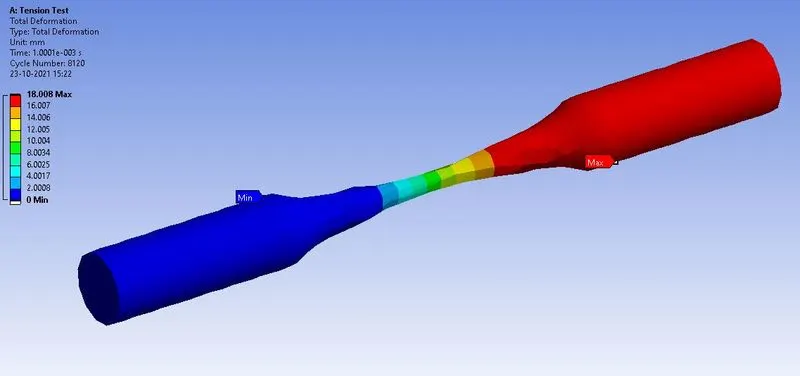
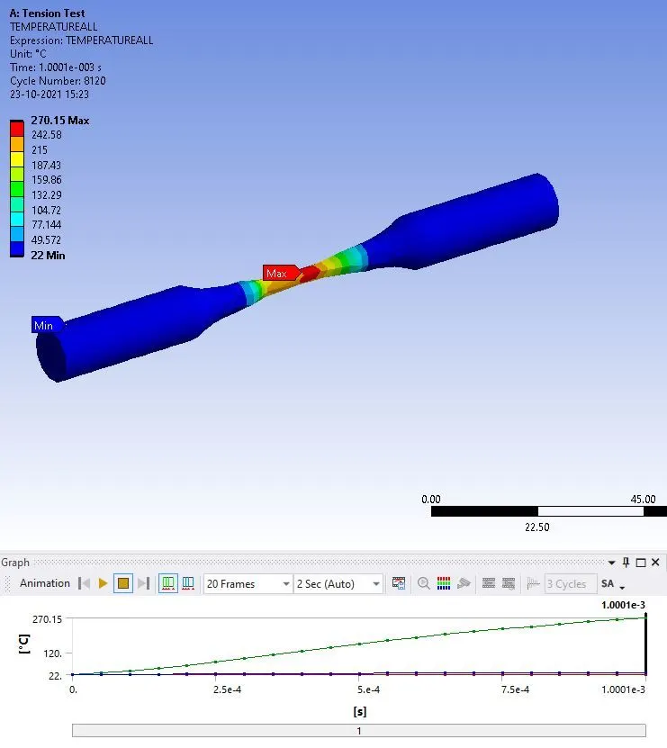
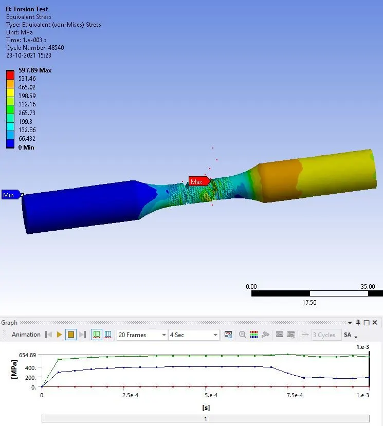
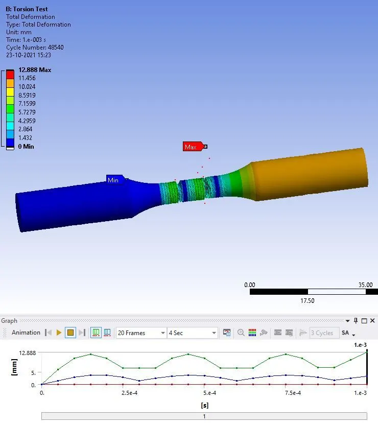
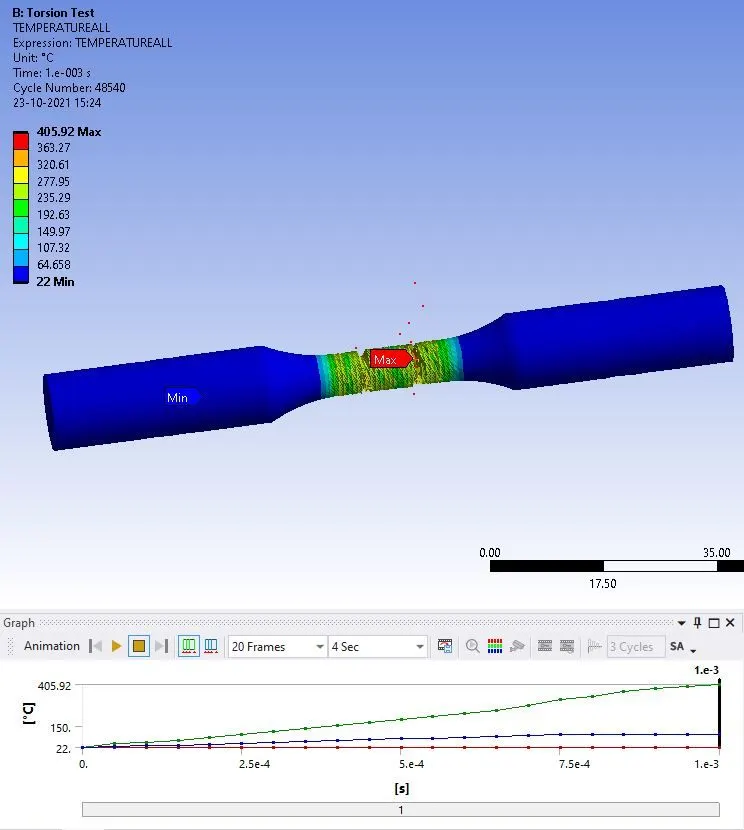
In the solution, the results were requested for the equivalent stress, total deformation, and temperature. All the results are shown in the figures below.
 |
|
Figure 7(a): Equivalent stress in the specimen of tensile test, with maximum stress of 636.82 MPa. |
 |
|
Figure 7(b): Total deformation in the specimen of tensile test with maximum deformation of 18 mm. |
 |
|
Figure 7(c): Temperature change in the specimen of tensile test with the maximum magnitude of 270.15 ºC. |
 |
|
Figure 8(a): Equivalent stress in the specimen of torsion test, with maximum stress of 654.89 MPa. |
 |
|
Figure 7(b): Total deformation in the specimen of torsion test with maximum deformation of 12.88 mm. |
 |
|
Figure 7(c): Temperature change in the specimen of torsion test with the maximum magnitude of 405.92 ºC. |
CONCLUSION
This simulation was performed to study the procedure of simulating the tension and torsion test. An explicit dynamics module was chosen to solve the problem. In boundary conditions, in the tensile test, one end of the specimen was fixed, and a linear displacement was applied to the other end. And in the torsion test, one end of the specimen was fixed and a rotation was applied to the other end, using a cylindrical coordinate system.