Tension and Torsion test
AIM:
- To perform explicit analysis of Steel 1006 rod for Tension and Torsion test and evaluate the stress and deformation results.
OBJECTIVES OF THE PROJECT:
- To assign Steel 1006 material for rod.
- To define coordinate systems.
- To define Mesh method and Face sizing.
- To mesh the model.
- To evaluate the stress, deformation and strain in the work piece.
PROCEDURE:
- TENSION TEST:
- OPEN WORKBENCH21 > NEW PROJECT > EXPLICIT DYNAMICS.
- This will start a new explicit dynamics project.
- Rename the project as tension test.
- Go to ENGINEERING DATA > EXPLICIT MATERIALS > STEEL 1006 > ADD.
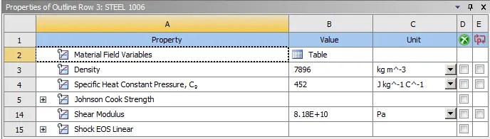
- Then double click on Geometry. This will open the Spaceclaim.
- In Space claim check the model for any dents or irregularities.
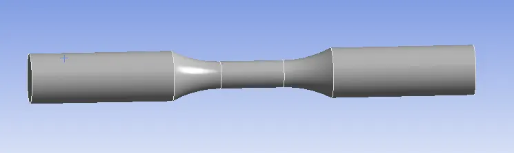
- The geometry looks good, exit the Spaceclaim.
- Then double click on Model. This will open Mechanical module.
- Now, rename the geometry as bar.
- Then assign Steel 1006 to the bar.
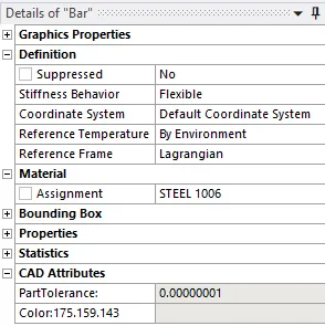
- Then go to coordinate systems and add new coordinate systems for the faces.
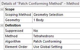
- Now, go to MESH > INSERT METHOD > GEOMETRY = BODY > METHOD = TETRAHEDRONS.
- MESH > INSERT > FACE SIZING > GEOMETRY = RIGHT FACE > TYPE SPHERE OF INFLUENCE > SPHERE SYSTEM = COORDINATE SYSTEM 2 > SPHERE RADIUS = 22MM > ELEMENT SIZE = 3MM.
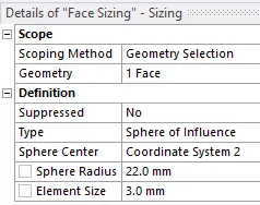
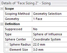
- Similarly, MESH > INSERT > FACE SIZING > GEOMETRY = LEFT FACE > TYPE SPHERE OF INFLUENCE > SPHERE SYSTEM = COORDINATE SYSTEM 1 > SPHERE RADIUS = 22MM > ELEMENT SIZE = 3MM.
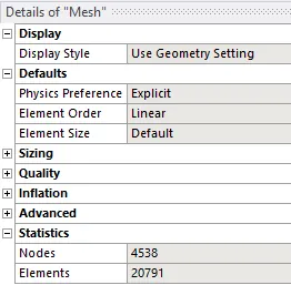
- Now, MESH > GENERATE MESH.
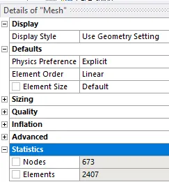
- The mesh will be generated on the model.
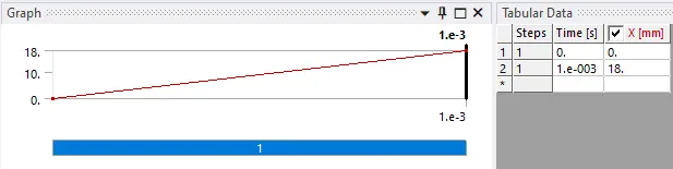
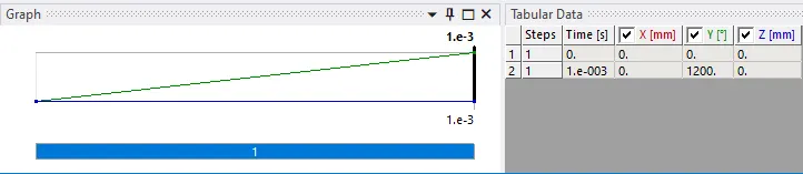
- Then go to STATIC STRUCTURAL > ANALYIS SETTINGS > NO OF STEPS = 1 > END TIME = 1E-3.

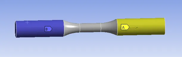
- Go to EXPLICIT DYNAMICS > INSERT > DISPLACEMENT > GEOMETRY = RIGHT FACE > X COMPONENT = 18MM.
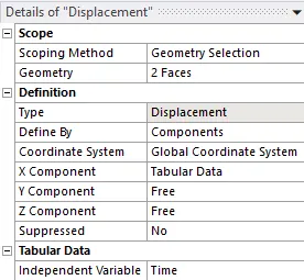
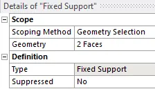
- Go to EXPLICIT DYNAMICS > INSERT > FIXED SUPPORT > GEOMETRY = LEFT FACE.
- Then, go to SOLUTION > INSERT > STRESS > STRAIN > DEFORMATION.
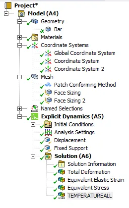
- This will set the output results.
- Then SOLUTION > SOLVE.
- TORSION TEST:
- CREATE DUPLICATE OF TENSION TEST > RENAME > TORSION TEST.
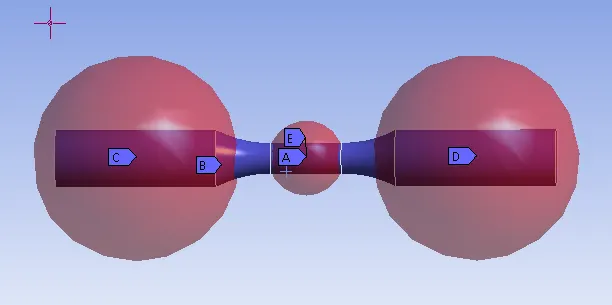
- Go to COORDINATE SYSTEM > ADD > TYPE = CYLINDRICAL > FACE = CENTER.
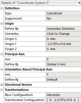
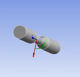
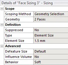
- Now, go to MESH > INSERT > FACE SIZING > GEOMETRY = TAPERED FACES > ELEMENT SIZE = 1.5MM.
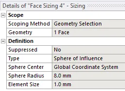
- MESH > INSERT > FACE SIZING > GEOMETRY = CENTER FACE > TYPE = SPHERE OF INFLUENCE > SPHERE RADIUS = 8MM > ELEMENT SIZE = 1MM.
- Now, MESH > GENERATE MESH.
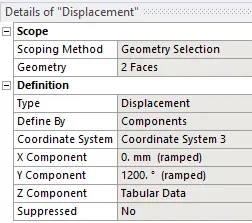
- Then, go to EXPLICIT DYNAMICS > DISPLACEMENT > COORDINATE SYSTEM = COORDINATE SYSTEM 3 > Y= 1200DEG.
- Now, go to SOLUTION > SOLVE.
RESULTS:
- TENSION TEST:
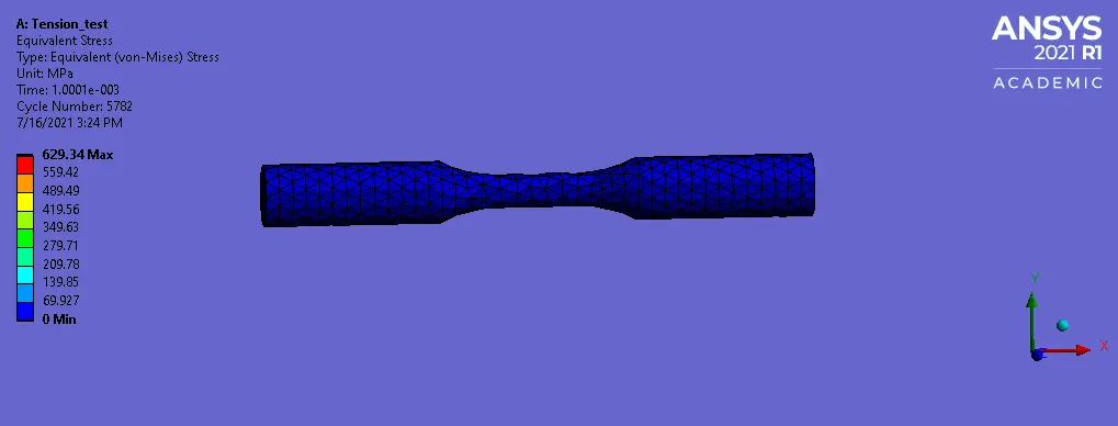
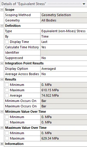
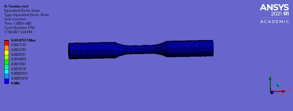
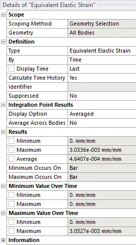
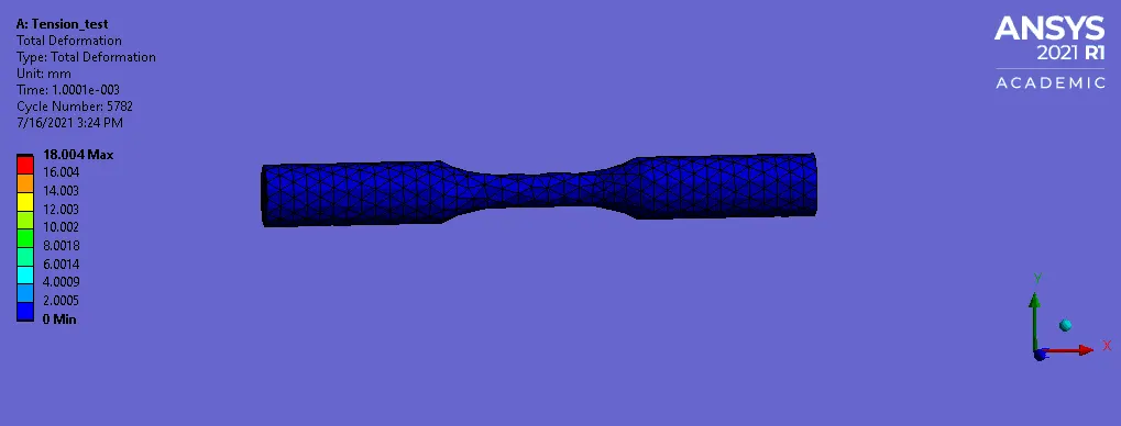
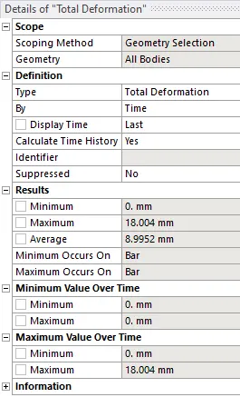
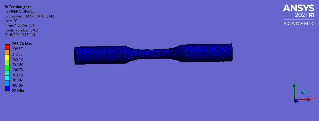
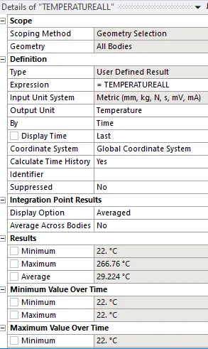
- TORSION TEST:
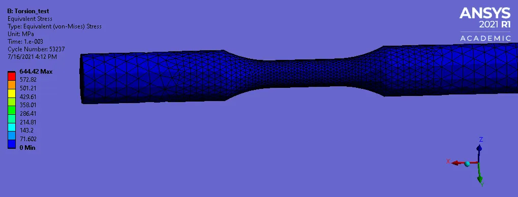
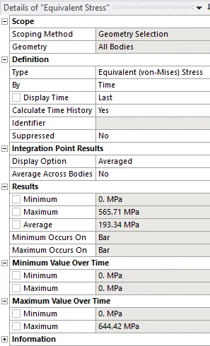
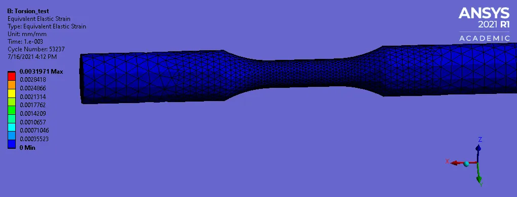
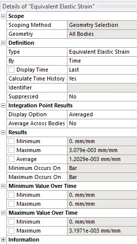
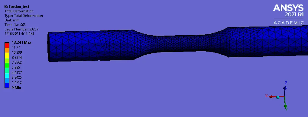
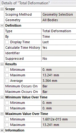
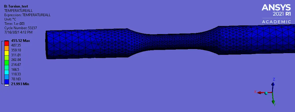
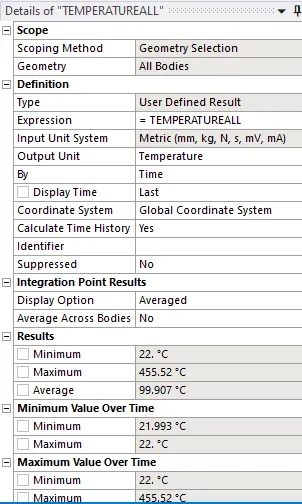
COMPARISON TABLE:
| Stress (MPa) | Strain | Deformation (mm) | Temperature (deg C) | |
| Tension test | 610.15 | 3.0336E-3 | 18.04 | 266.76 |
| Torsion test | 565.71 | 3.079E-3 | 13.241 | 455.52 |
LEARNING OUTCOMES:
- To setup explicit dynamics analysis for tension and torsion test.
- To assign material from the material library.
- To define mesh method and face sizing.
- To define displacement and fixed support.
- To define output results.
CONCLUSION:
- By performing this project we conclude that the Tension and Torsion test of the Steel 1006 bar is performed and the stress, strain, deformation and temperature results are obtained.
MODEL LINK:
https://drive.google.com/file/d/187pJF-StlnXob2myyxIiAUHMeVb5e3Hs/view?usp=sharing