Week 9 Tension and Torsion test challenge
- Objective: To perform tension and torsion test on the given specimen.
- Procedure:
Open the explicit dynamic analysis system in the Project schematic. The material used for the analysis is explicit material - Steel 1006 Add the material in the material library. Now proceed to import the
geometry. Import the Geometry. Open the Geometry in SpaceClaim. Ensure the geometry is properly imported by doing quick visual inspection. The geometry is properly imported as observed.
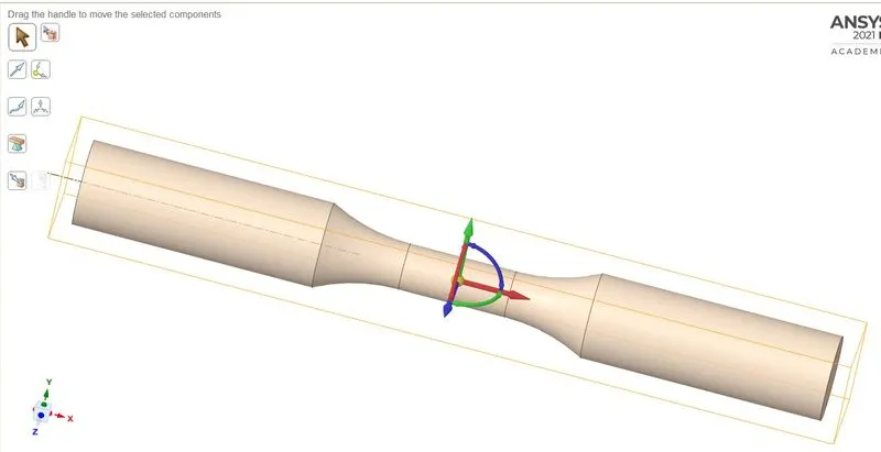
Update and open the mechanical module. Assign the material Steel 1006 for the specimen. Now mesh the model. We will insert face sizing for both the side ends of the specimen. Sphere of influence will be
defined, for that, create co-ordinate systems on both the end. Right click on the end face and select click on Create co-ordinate system. Similarly, create another co-ordinate system on the other side.
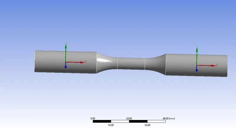
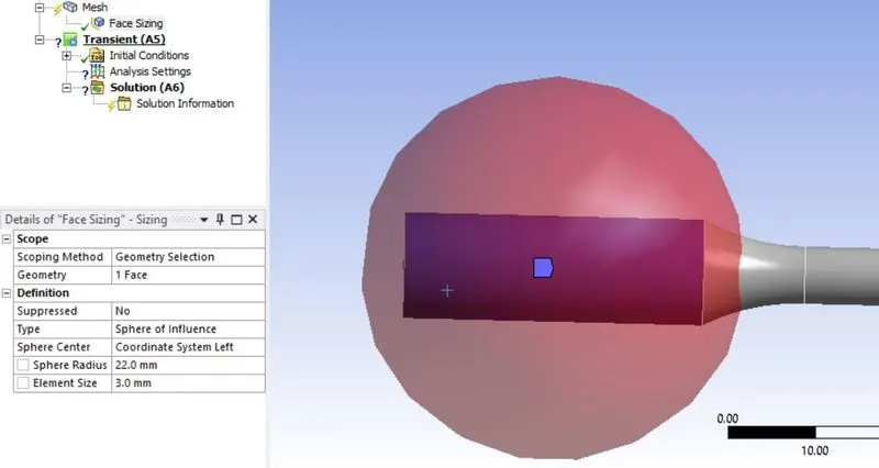
Go to Mesh > Insert >sizing. Select the left side end of the specimen. Select type as Sphere of Influence. For sphere center, select the co-ordinate system created on the left side. Enter sphere radius = 22 mm
and element size of 3mm.
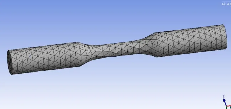
Similarly, insert face sizing for the right hand side of the specimen. To mesh the specimen with Tetrahedrons elements, insert methd. Go to Mesh > Insert > Method. Select the type as Tetrahedrons and generate
the mesh.
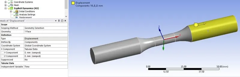
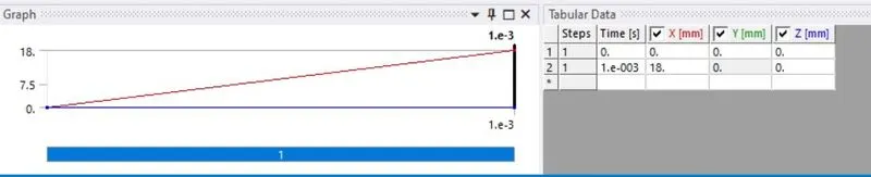
Now define the end time for the simulation. Go to Analysis settings > End time. Enter end time = 1e-3 s. Now insert the displacement load for the specimen end. Displacement of 18 mm is to be applied. Go
to Explicit dynamics > Insert > Displacement. Select the right end of the specimen and apply the displacement. Since we want to avoid any unnecessary motion of the specimen during displacement, enter the Y
and Z components of displacement = 0. For X component, enter the displacement in tabulated form as shown below:
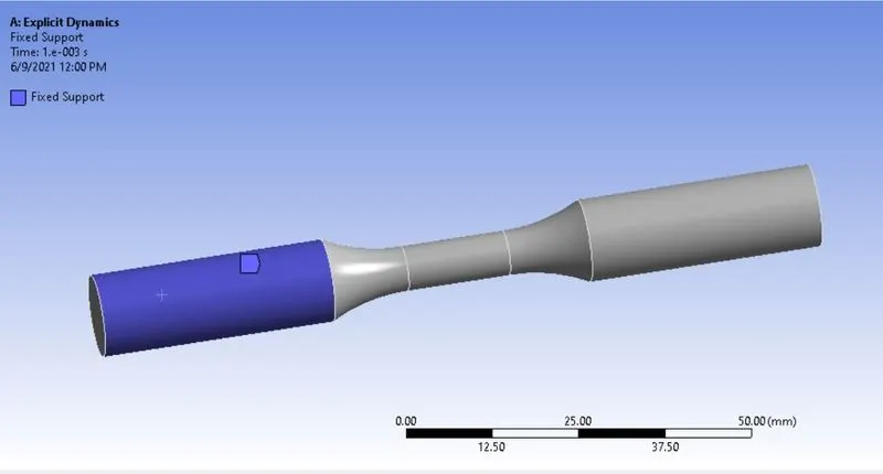
Fix the other end on the left side. Insert Fixed support at the right side end of the specimen.
The case setup is complete. List the required results and run the simulation.
Case setup for Torsion test:
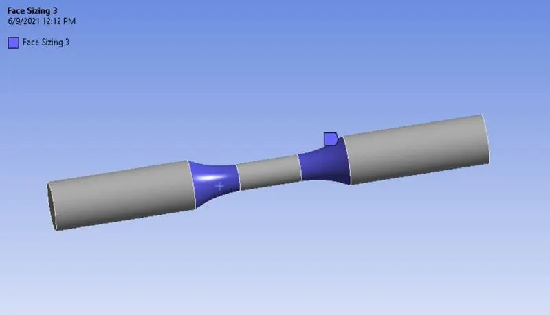
To perform the torsion test, duplicate the tension test analysis in the Project Schematic. Open the Mechanical module. Refine the mesh in the middle portion which is the critical area from analysis point of view for
the torsion test. Go to Mesh > Insert > Sizing. Select the displayed faces to mesh with element size of 1.5mm.
In the middle portion, the mesh is refined using sphere of influence of 8 mm radius with element size of 1 mm and the component is meshed.
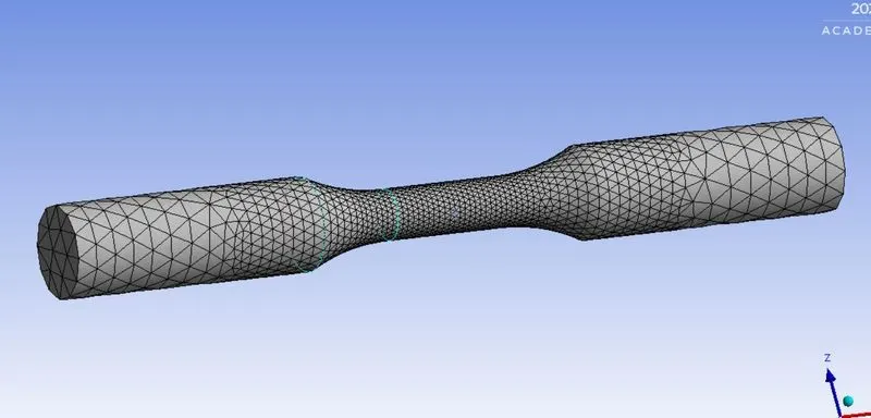
Now to apply rotational load, create a cylindrical co-ordinate system at the middle portion.
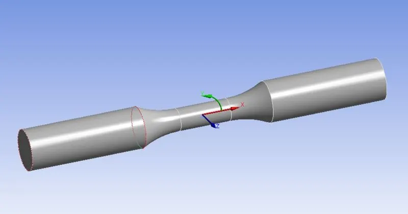
As seen above, the direction of rotation is not properly aligned wrt the longitudinal direction. Align the direction of rotation properly.
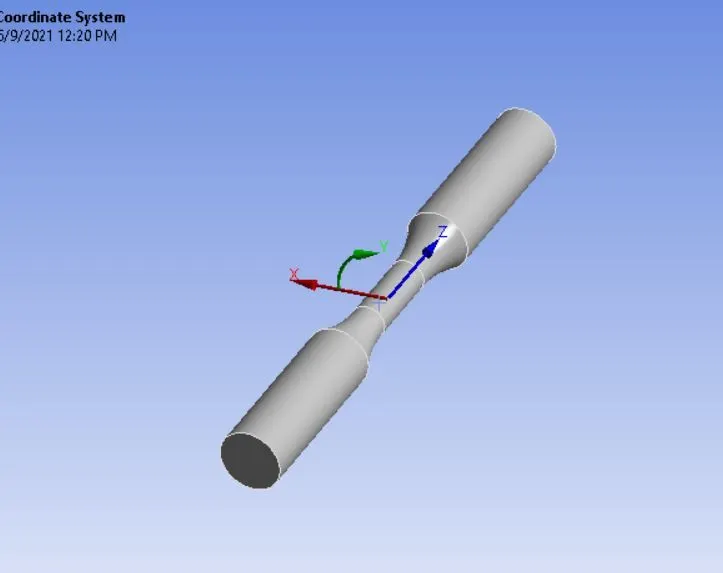
Now apply the displacement load for rotation by updating the previous displacement load. Go to Explicit Dynamics > Displacement. Set the co-ordinate system to cylindrical co-ordinate system. For constraining
unnecessary motion, set the X and Z components to 0. For Y load, enter the data in tabular form. Rotation of 1200° is applied.
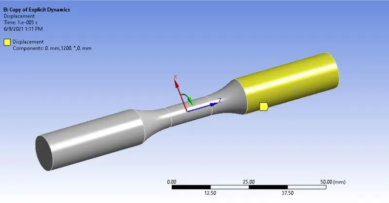
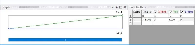
Case setup is now complete. Run the simulation and view the results.
- Results:
Tension test: Stress contour in the model:
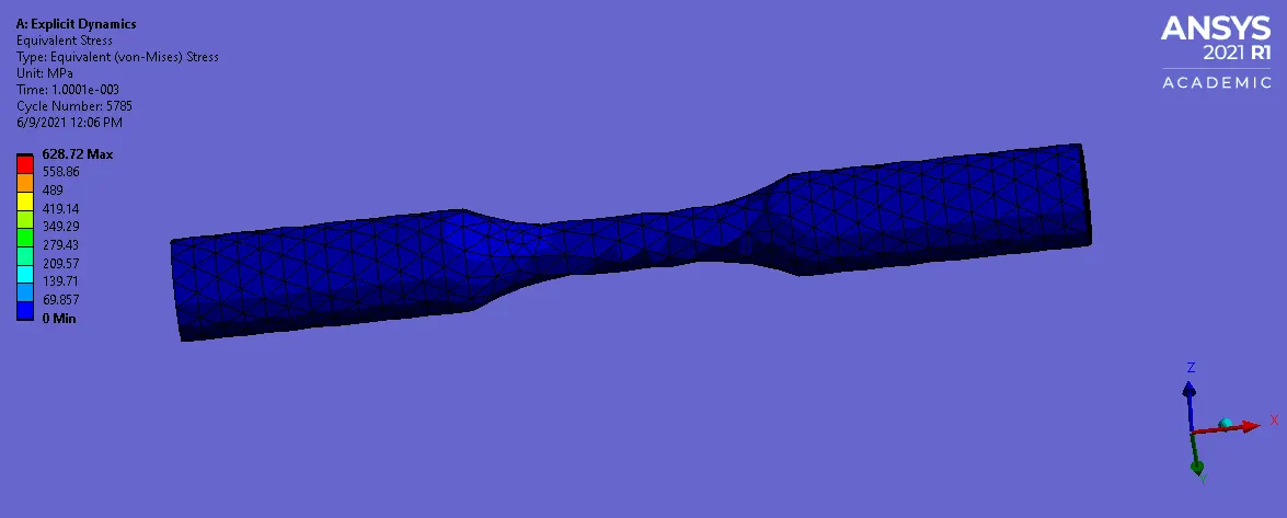
Max stress of 628.72 Mpa is observed in the necking region. It makes sense, since this is also the area with max. strain.
Total Deformation in the model:
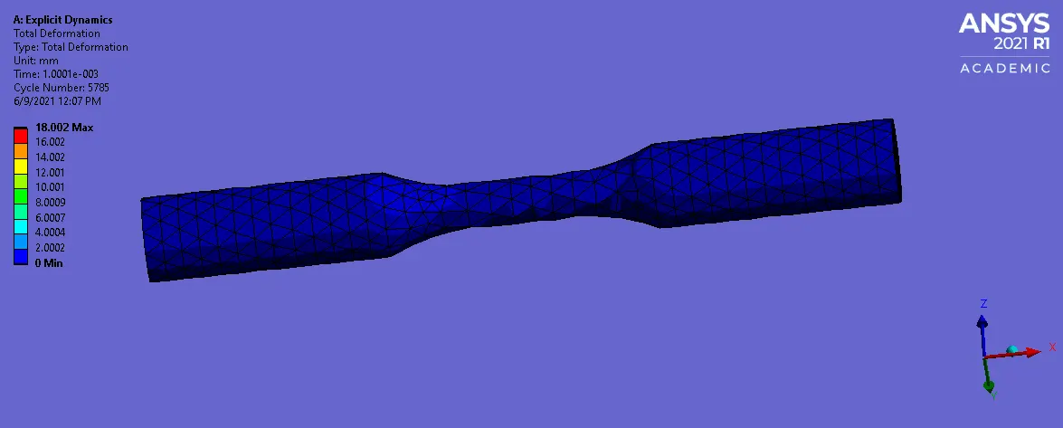
Total deformationof 18 mm is observed at the specimen end which corresponds to the applied load displacment of 18 mm. This shows that the displacement is properly is properly applied at the speciment end.
Temperature
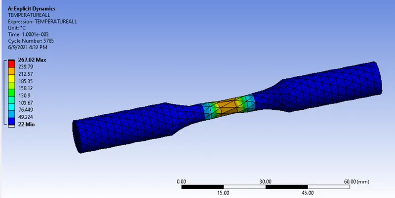
Max temperature is observed at the necking region. Temperature of 267°C is observed.
Results for Torsion Test:
Stress contour in the model:
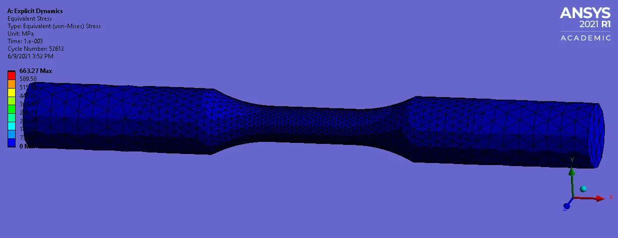
Max stress of 663.27 Mpa is observed at the gauge length of the specimen. Element erison is observed at the middle as the rotation is applied. Elements are seen flying off from the model due to failure.
Total Deformation in the model:
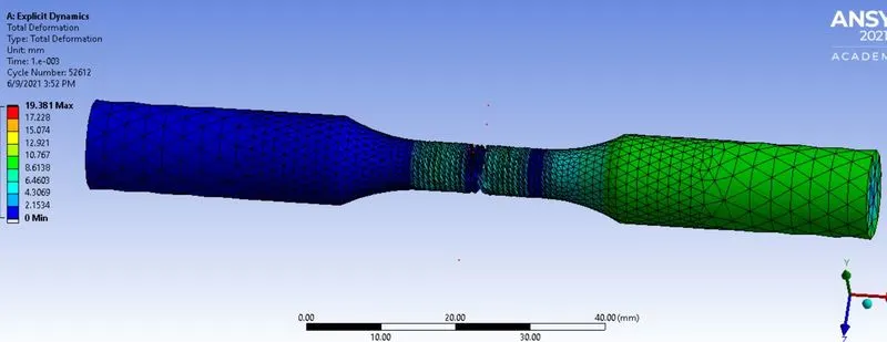
Total deformation of 19.38 mm is observed in the model.
Temperature od the model:
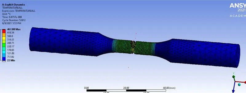
Highest temperature of 467.88°C is recorded at the location of failure.
- Conclusion: Thus the use of explicit analysis system to perform the torsion and tension test on the given specimen has been learned. Also, the behaviour of the model (max stress & temperature location and
deformation) is the same that would be expected in real scenario, thus indicating that the simulation is properly gone through.