Week 9 Tension and Torsion test challenge
Tesnion Test:
Tensile tests are used to determine how materials will behave under tension load. In a simple tensile test, a sample is typically pulled to its breaking point to determine the ultimate tensile strength of the material. The amount of force (F) applied to the sample and the elongation (∆L) of the sample are measured throughout the test. Material properties are often expressed in terms of stress (force per unit area, σ) and strain (percent change in length, ε). To obtain stress, the force measurements are divided by the sample’s cross sectional area (σ = F/A). Strain measurements are obtained by dividing the change in length by the initial length of the sample (ε = ∆L/L). These values are then presented on an XY plot called a stress-strain curve. Testing and measuring procedures vary based on the material being tested and its intended application.
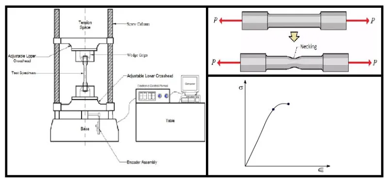
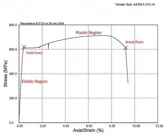
Tensile testing is critical for selecting appropriate materials during research and development. Tensile testing can also be used to verify that materials adhere to minimum strength and elongation requirements.
Torsion Test:
Torsion tests twist a material or test component to a specified degree, with a specified force, or until the material fails in torsion. The twisting force of a torsion test is applied to the test sample by anchoring one end so that it cannot move or rotate and applying a moment to the other end so that the sample is rotated about its axis. The rotating moment may also be applied to both ends of the sample but the ends must be rotated in opposite directions. The forces and mechanics found in this test are similar to those found in a piece of string that has one end held in a hand and the other end twisted by the other.
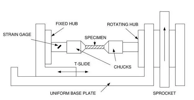
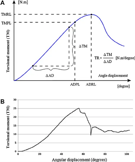
The purpose of a torsion test is to determine the behavior a material or test sample exhibits when twisted or under torsional forces as a result of applied moments that cause shear stress about the axis. Measurable values include: the modulus of elasticity in shear, yield shear strength, torsional fatigue life, ductility, ultimate shear strength, and modulus of rupture in shear. These values are similar but not the same as those measured by a tensile test and are important in manufacturing as they may be used to simulate the service conditions, check the product’s quality and design, and ensure that it was manufactured correctly.
Objective:
To perform the tension and torsion test on the specimen provided in the challenge. For the tension test, one end of the specimen is to be displaced by 18mm while keeping the other fixed. For the torsion test, one end of the specimen is to be displaced by an angle of 1200 deg. Total deformation, equivalent stress, and temperature of the specimen needs to be calculated.
Preprocessing for the analysis:
1. Geometry creation
The model required for this challenge was obtained from the one given in the problem. The model is checked in modeler or spaceclaim for any irregularities in the model.
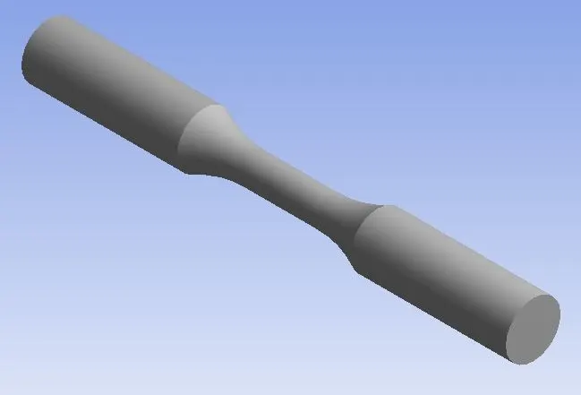
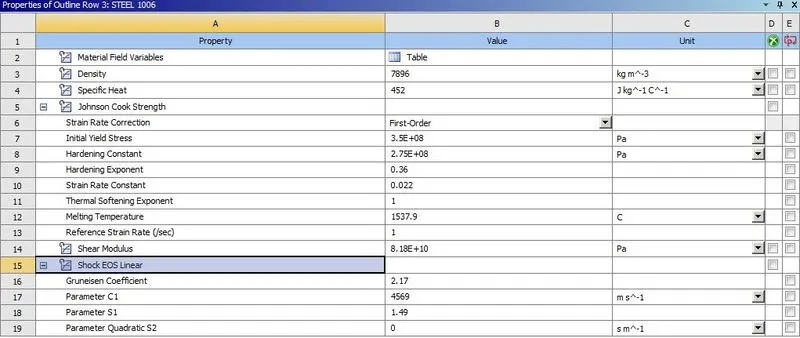
2. Material Selection
Since Structural steel is not an explicit material, a new material is added to the simulation from 'engineering data' i.e., steel 1006.
3. Connections & Coordinates
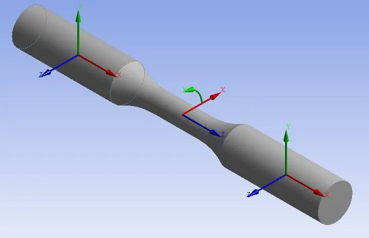
Since we are not studying any relative motion, any default connection that might have been introduced is deleted. This simulation model does not have any contacts.
For tension test:
However, 2 new co-ordinate systems are introduced at each end of the specimen in order to facilitate user defined meshing in that area.
For torsion test:
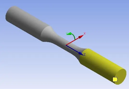
A cylindrical co-ordinate system is introduced at the mid section of the specimen where berakage will take place in order allow for rotaional load to be given to the specimen with respect to that co-ordinate system. Care must be taken that the rotation ordinate matches the rotation of the specimen.
4. Meshing
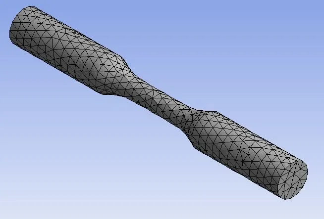
A tetrahedral method of meshing is selected for the entire specimen so that entire specimen is meshed with tetrahedral elements alone.
For tension test:
The two co-ordinate systems created at the ends of the specimen are used to modify mesh sizing by introducing a sizing component there by way of sphere oif influence. the sphere of influence is set between 18-22 mm in order to encompass noth the lobes entirely. The element size is kept to 3 mm and the rest of the mesh is automatically meshed.
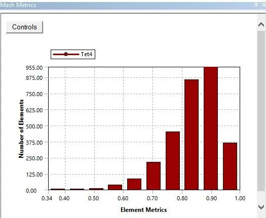
For torsion test:
Apart from the two spheres of influence at the extreme lobes of the specimen, the three remaining sections in the middle are also given a size of 1.5 mm and 1 mm. The mid section element's are given element size of 1 mm while the two sections around it are given a size of 1.5 mm.
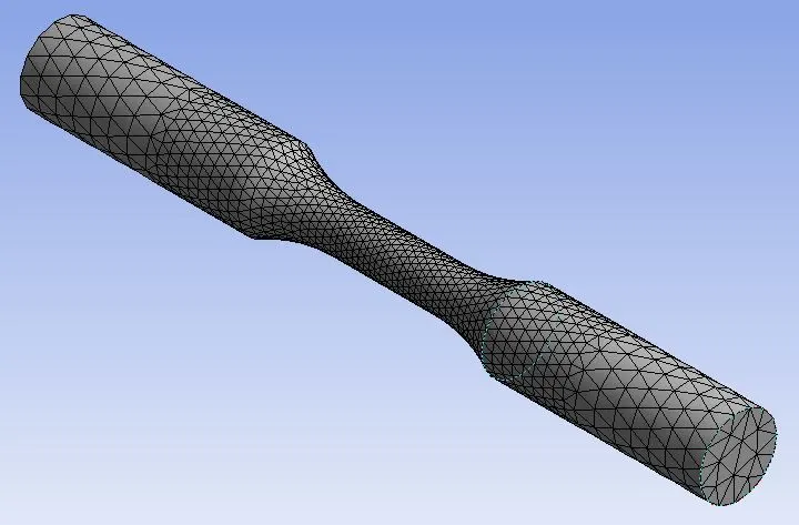
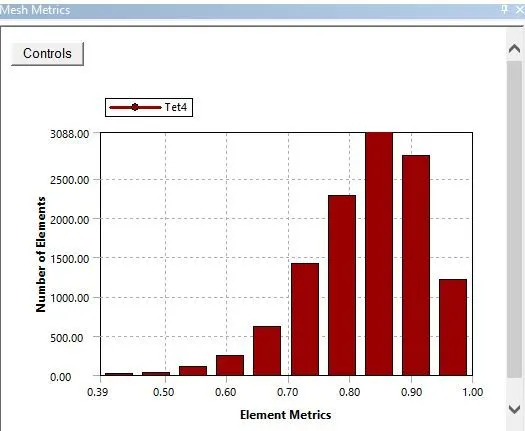
5. Analysis settings:
The end time of the simulation is set to 0.001s as the transient analysis is used for events involving shorter time periods and material testing occurs in splitsecond intervals. Rest of the settings are left undisturbed.
6. Loads and boundary conditions:
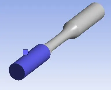
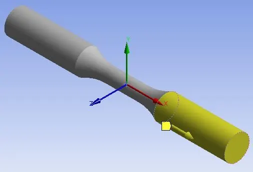
Since we have to keep one end of the specimen fixed, a conndition of fixed support is applied on of the two lobes of the specimen.
For Tension test:
A displacement load of 18 mm is given to the other end of the lobe in x-direction with respect to global co-ordinate system.
For Torsion test:
A displacement load of 1200 deg. is given to the other end of the lobe in z-direction with respect to newly defined cylindrical co-ordinate system.
Solution and postprocessing:
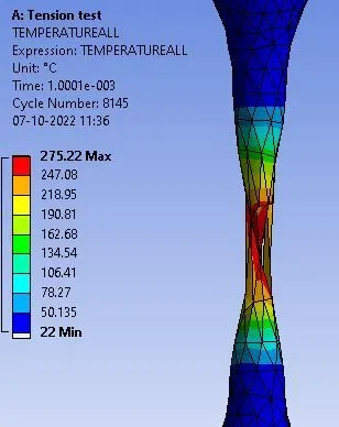
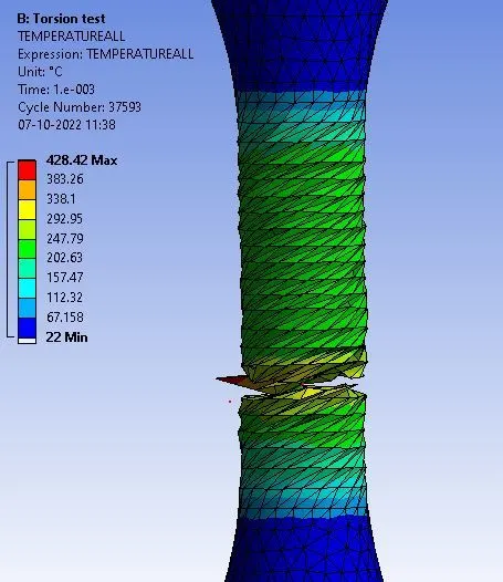
while stress and strain curved are defined pre-solving, temperature results in this simulation aret be defined as a user defined result from the worksheet section in the ribbon section of the window after running the simulation.
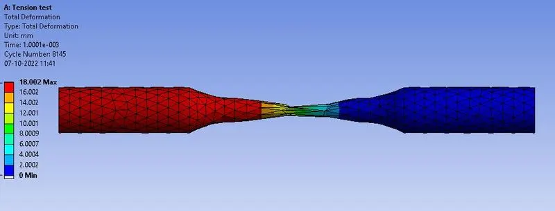
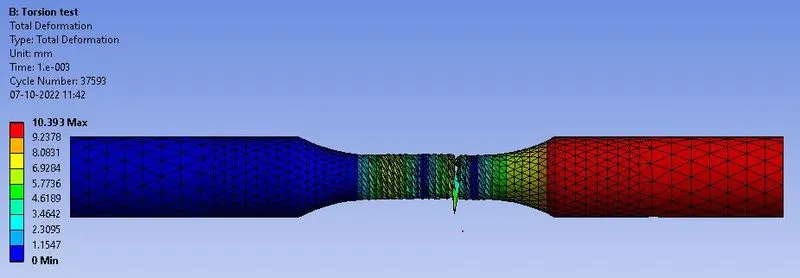
1 Total deformation:
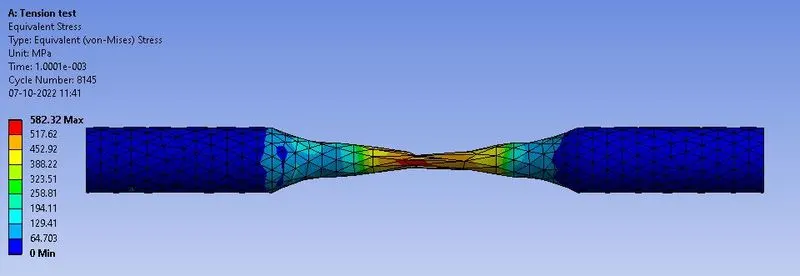
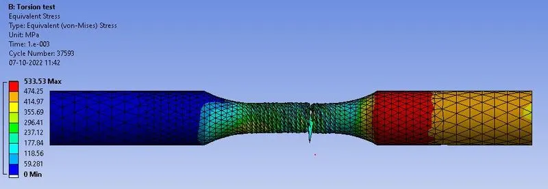
2. Equivalent stress
3. Temperature:
Results:
| Total Deformation (mm) | Equivalent stress (MPa) | Temperature (°C) | |
| Tensile Test | 18.002 | 582.32 | 275.22 |
| Torsion test | 10.32 | 533.53 | 428.42 |