Week 9 - Project - Master Section Development
AIM: To develop the class B and class C surfaces of the master section of B-Pillar by using the surface command and performing the draft analysis for the surfaces and the features given in the CAT part file.
Given inputs:
- A-Surface
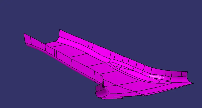
- Master Sections-1 , Mastersection Sections-2
- Master Sections are the guides for design requirements that shape the component after the technical styling of class A surfaces.
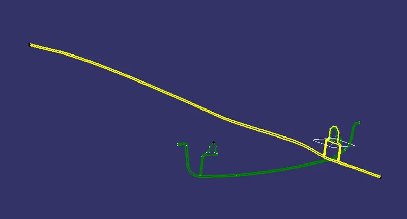
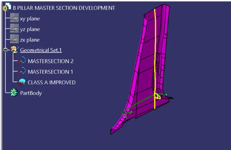
- Distance Between Ribs Should Be 50mm
B-Pillar:
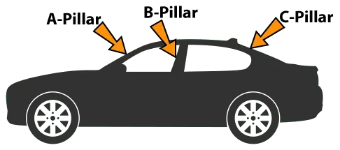
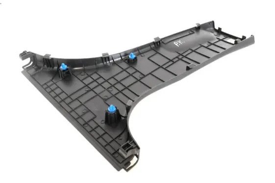
- The B-pillar is ordinarily a closed-steel structure welded at the base to the car's rocker board and floor pan, just as on the top to the rooftop rail or board.
- This pillar offers underlying help for the vehicle's rooftop board and is intended for locking the front entryway and mounting the pivots for the back entryways. The B-Column is the central pillar of the vehicle. This column is a Sheet Metal Part that is welded in the Body in white of the vehicle.
- The B-Column trim is connected to The B-Column and improves the stylish look of the vehicle. Generally, the trims are fabricated by the injection molding process.
- The plan of the B-pillar is deliberately done to make the part manufacturable and usable in the inside of the car.
- While assembling a section through infusion trim a lot of imperfections can happen on the plastic part which will obliterate the appearance of the board. The plan needs to be made so that every one of the blunders can be corrected.
Procedure:
The improved class-A Surface is the given surface, which checks the irregularities or gaps between the surfaces. Use a boundary option to check whether they are any gaps between the surfaces.
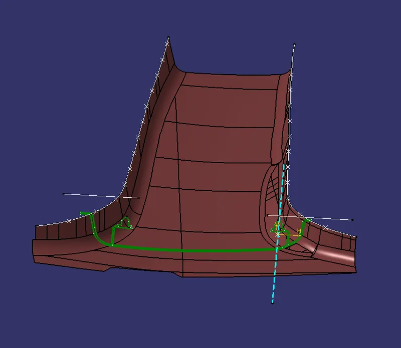
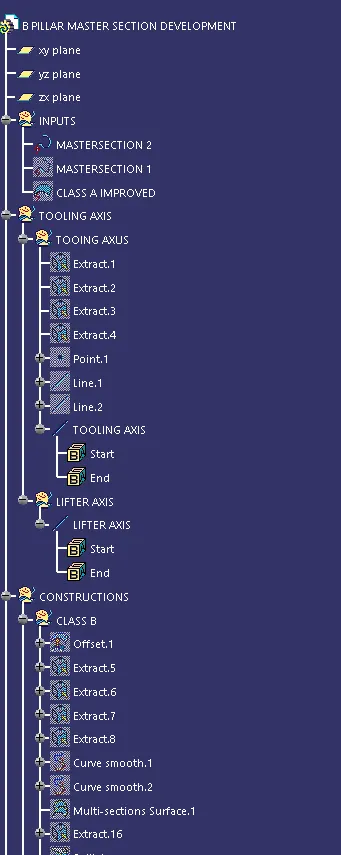
- To create a tooling axis, insert a geometrical set for the tooling axis creation. Use the master section lines, extract the feature lines, and by using the bisecting method create reference lines for the tooling axis. Bisect them to get the final line and rename it as the tooling axis.
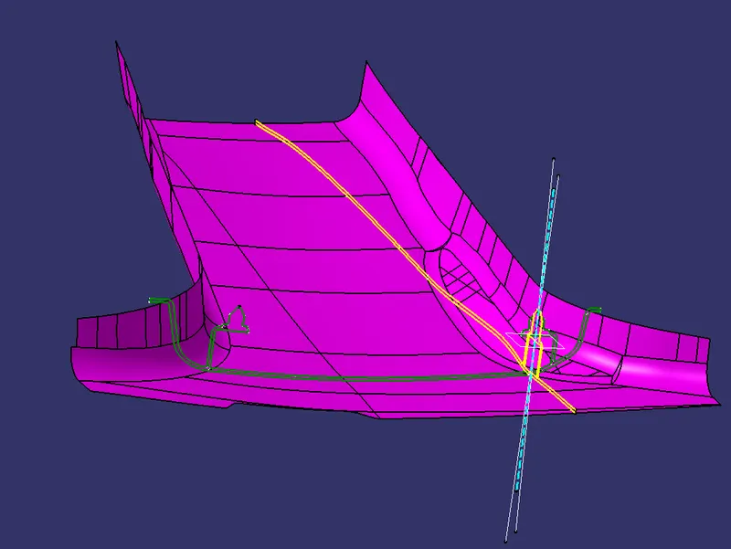
- With reference to the given class -A surface class-B surface is created. By extracting the boundaries of the surface, offset the surface to 2mm.
- There will be an improper surface present on the class-B surface, which can be corrected by multiple extracting the boundaries of the gap and using the curve smooth line where the curves are extracted.
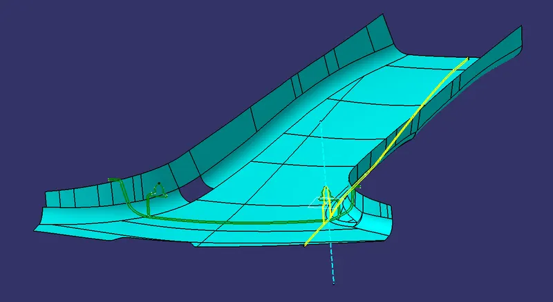
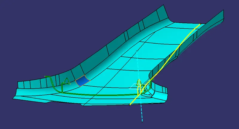
- By using the multi-section surface define and fill the gap between the surface. Select the guiding curves and the direction on both sides should be similar.
- Join the newly created surface with class B by using the join surfaces option. A class-B surface is created.
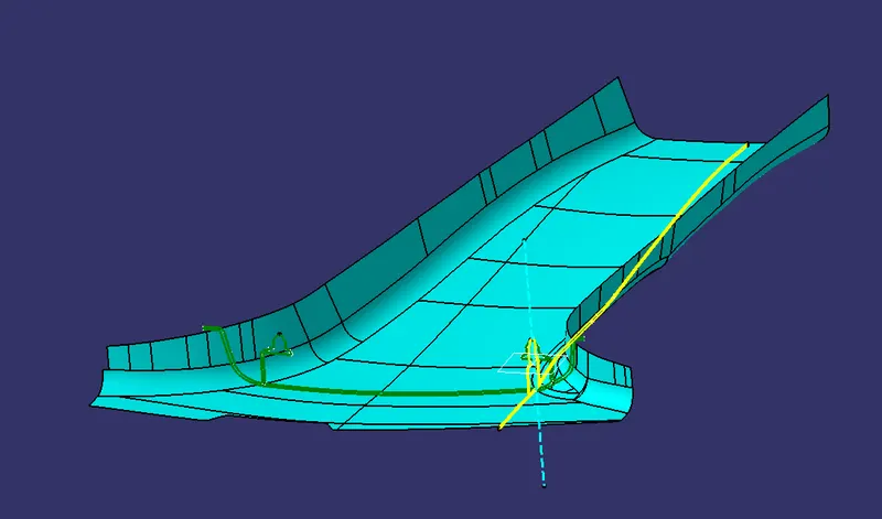
- Insert a geometrical set and rename it as flange creation, add another set under it and rename it as flange-1.
- Create a plane through the master section point and intersect it in XY-plane with the surface.
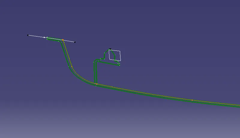
- Unhide the class-A surface and using the multiple extract option extract the boundaries and corresponding surfaces through the boundary.
- Use the tangent continuity for the boundaries and no-propagation for the surface extraction.
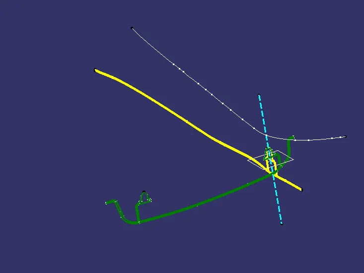
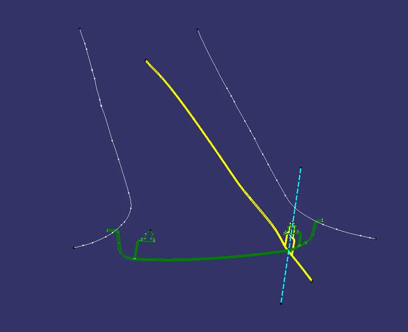
- By using a sweep option with the reference surface, guide curve as the extracted boundary, reference surface as the extracted surfaces using no-propagation with an angle of 105 degrees with reference to the intersection line. select the outer direction for a sweep operation.
- Class-B with flange.
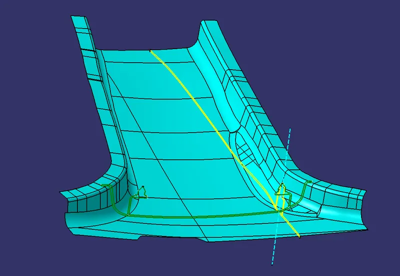
- Class-C is created with reference from the given class-A flange. Extract the boundaries of the surface by using multiple extracts, make sure that the straight curves are extracted first.
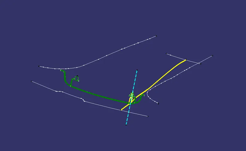
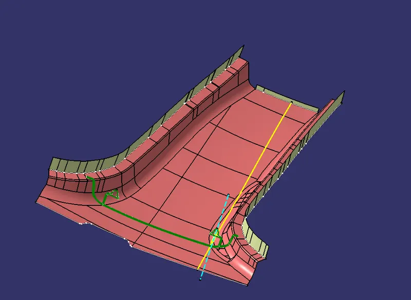
- Using sweep option- with draft direction as tooling axis and 3 degree draft angle sweep the selected boundaries towards inside of the component.
- Sweep length is maintained enough so that it can be trimmed properly with the other surface. If there are errors, extrapolate the sweep operations.
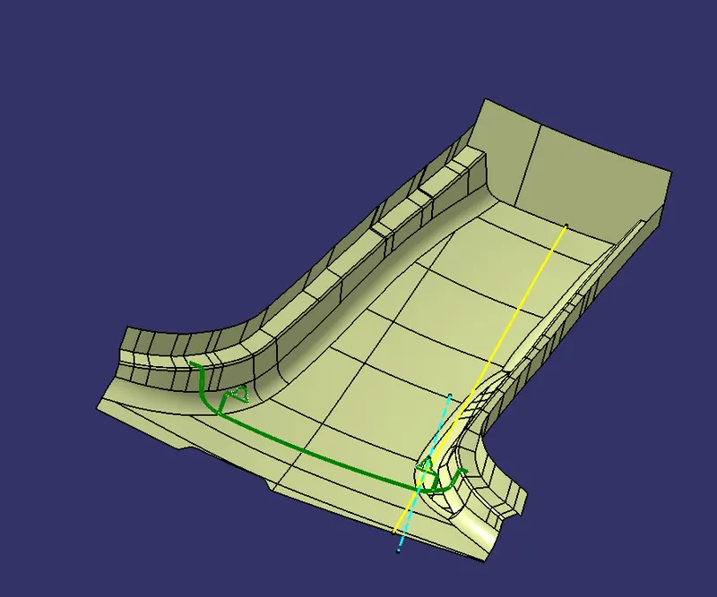
- Select the other portions of the boundaries and extract them separately. Use a multi section surface option to get the complicated curved surface in between the two swept surfaces.
- Make sure that the direction of the sweep and the guide curve is selected properly.
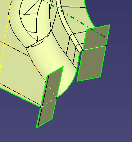
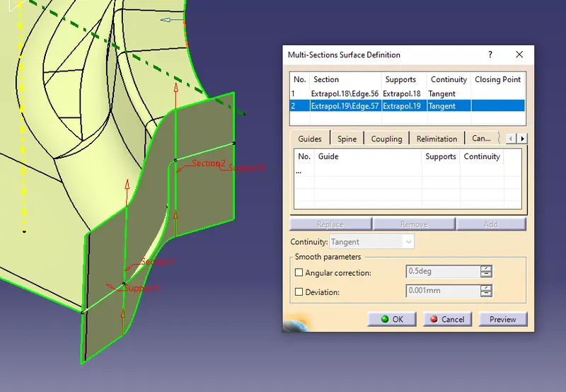
- Perform the similar operation to make the surfaces in the boundaries and the other half. Extrapolate them to intersect each other and trim them accordingly join the surfaces
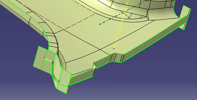
- Now extrapolate the boundaries of the class-A properly and trim them with the class-C surface. Class-C with class-A is created.
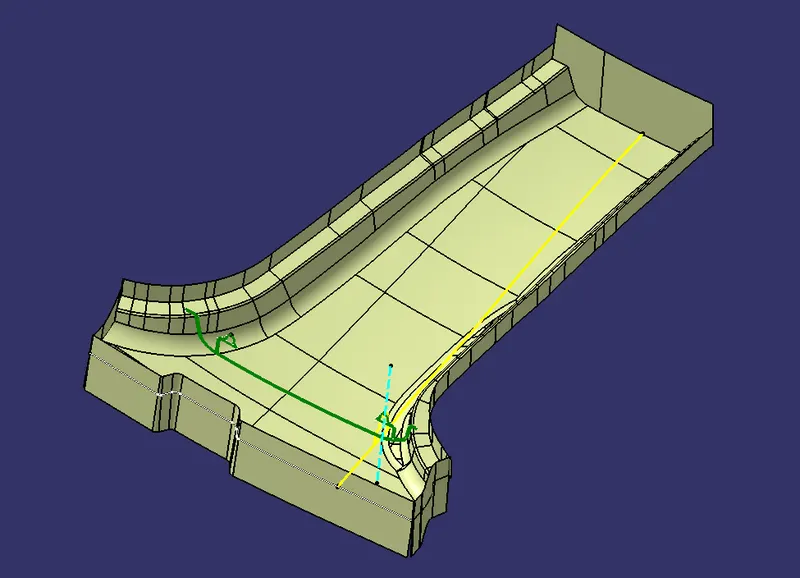
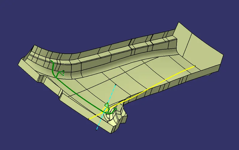
- Trim the class-A, class- B and class-C surfaces together to get the final trim closed surface. By clicking on the boundary option to make sure that the created surface is a closed body.
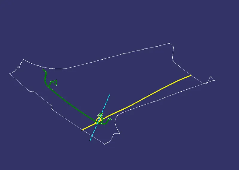
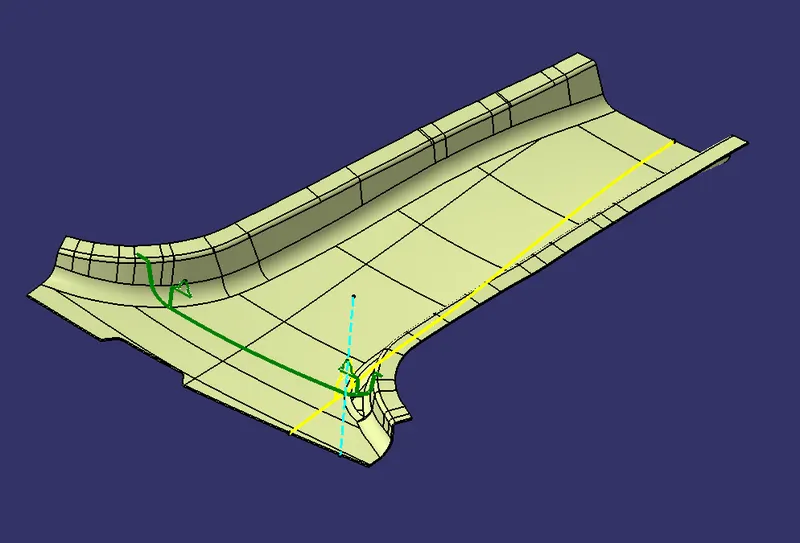
- Insert a part body and name it as B-pillar. Goto the part design and using the closed surfaces, create a solid body out of the closed surfaces B-pillar created.
- Features are created on the B-side. Insert a geometrical set and name it as B side features. Insert another set under it and rename it as Dog house design.
- Extract the lines for the dog house feature creation unhide the planes in perpendicular direction.
- Insert a positioned sketch for the dog house creation, create the two sketches in both the directions. Maintain the points equidistant from the centre axis and are iso- constrained.
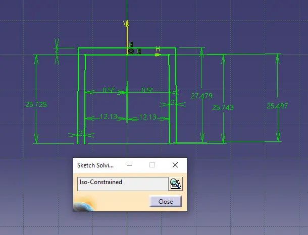
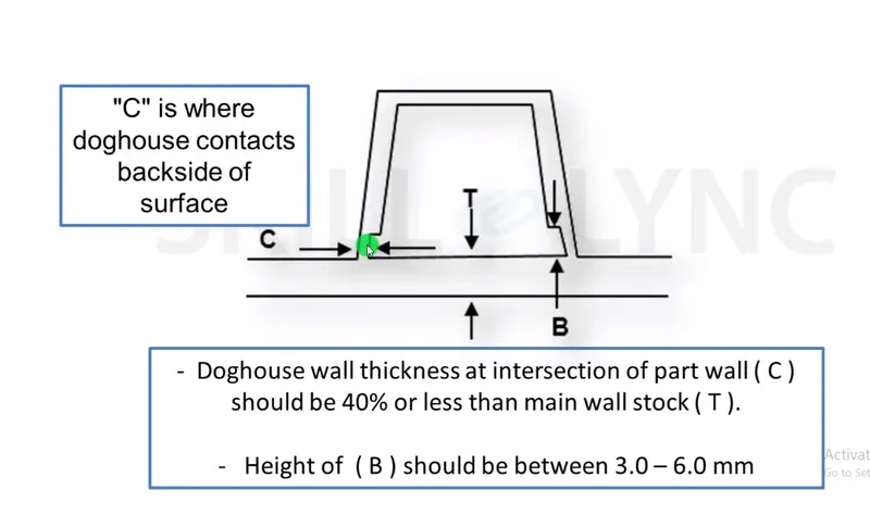
- Create a dog house and 4 way locator with the help of master section 1 and attach it to the main body.
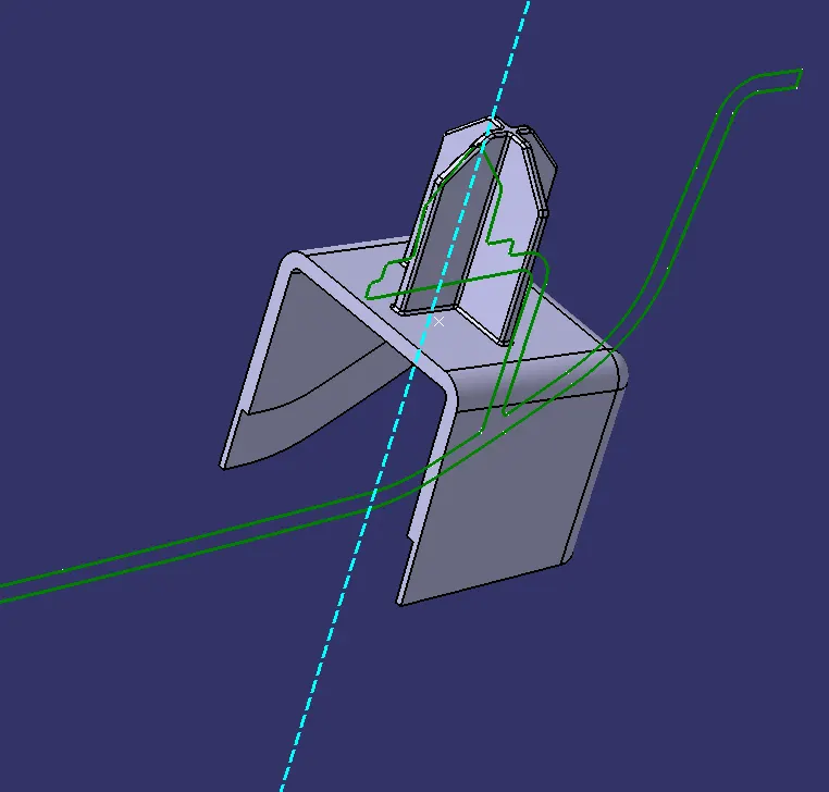
- The dog house which is on another side is created with the help of symmetry command by creating a point and XY-plane.
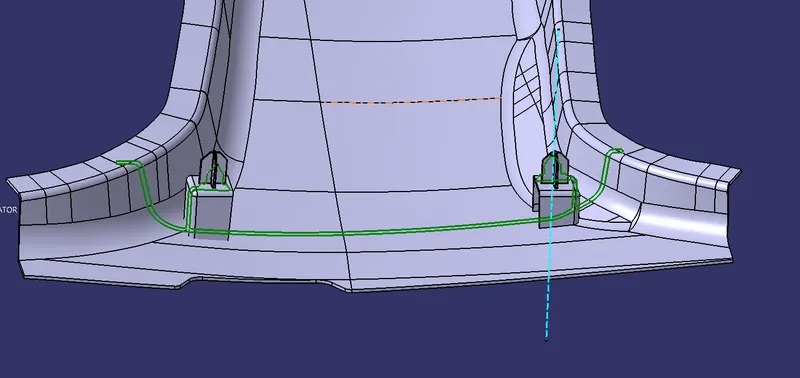
- Insert a geometrical set for the ribs creation which are created at equal intervals. Create a positioned sketch from the master section as reference.
- Maintain a minimum 50mm of gap between the two ribs.
- Off-set the class-B to 20mm and extract the boundaries with multiple extract options. By using points repetition with the help of a plane, create the multiple equidistant of 50mm points on the extracted boundary on both sides.
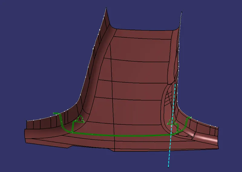
- The design parameters for the creation of ribs as shown below.
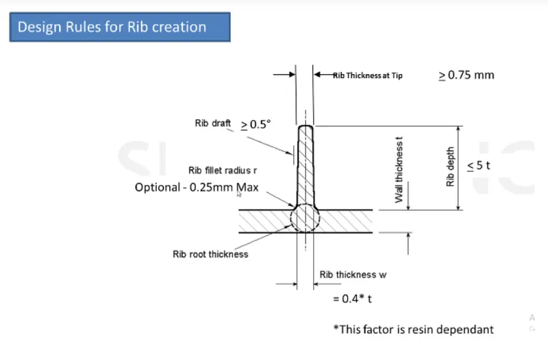
- Insert a part body for the Rib created. thicken the rib surface with 0.4mm in both the limits ie.. 0.8mm.
- Split it and draft the faces of the surface with 0.5 degrees and neutral surface as the base towards the class-B surface select the lifter axis as pulling direction and also add edge fillet of 3mm radius.
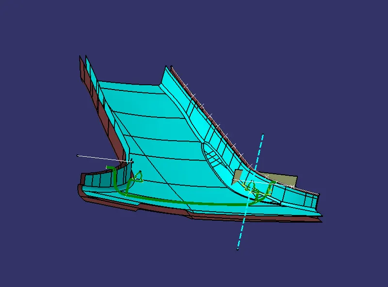
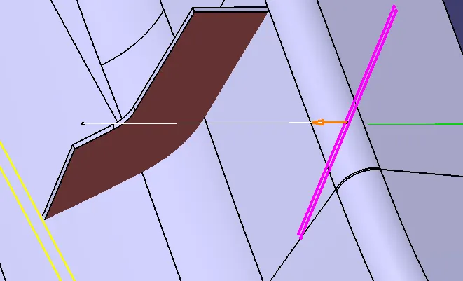
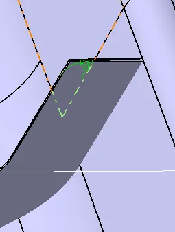
- By using the copy and paste specials procedure replicate the rib part body and translate with point to point option and select the repeated points on the extracted boundary.
- Perfrom the procedure for all the other points. By using Boolean operation ADD them to the main part body.
- Add the edge fillets for the edges joining the ribs and class-B surface.
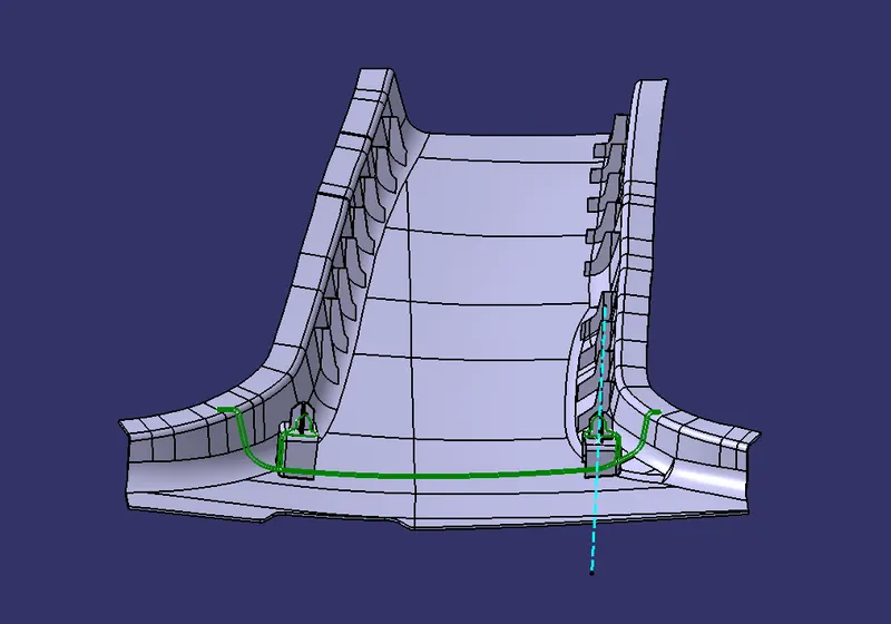
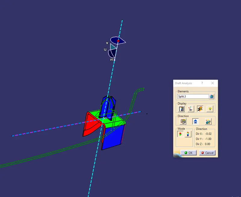
- Now perform the Draft analysis on the given class-A surface and unhide the main tooling axis. Goto insert command- Analysis- Feature draft analysis.
- Select the component, drag and place the compass on the tooling axis and check for the colour deviation with 3 degrees as the draft angle.
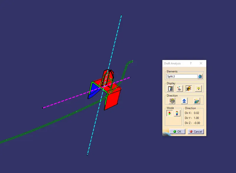
- From the view of tooling direction, the surface must be in green colour. The surface which is opposite from the tooling direction is represented in red colour and drafted surfaces are viewed as blue in colour.
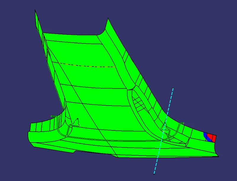
- Perform the draft analysis on the B-pillar. Dog house with 4 way locator both in main tooling axis and lifter tooling direction.
- Perform the draft analysis for the dog house separately with both tooling and lifter axis. The results are shown below.
Publication:
Publications allow you to modify a model without invalidating the features defined in the analysis document. If you modify the entity to which a publication refers in a CATIA V5 part or assembly, all of the features in the analysis document using that publication are updated to refer to the new entity.
To identify the easy location of the tooling axis, the tooling axis class-A surfaces and class B and class- c surfacesare published.
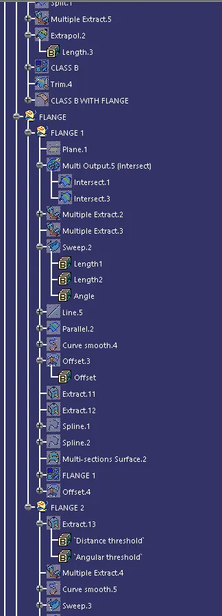
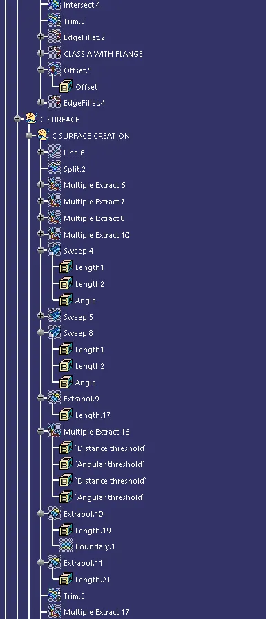
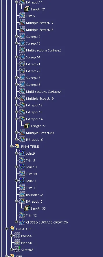
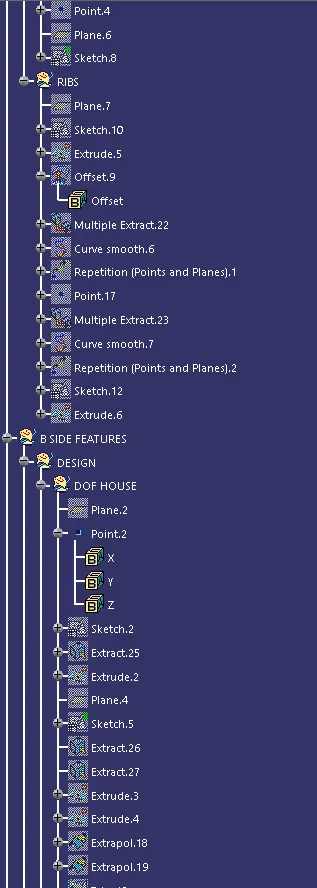
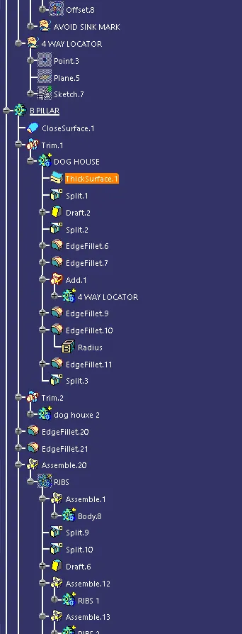
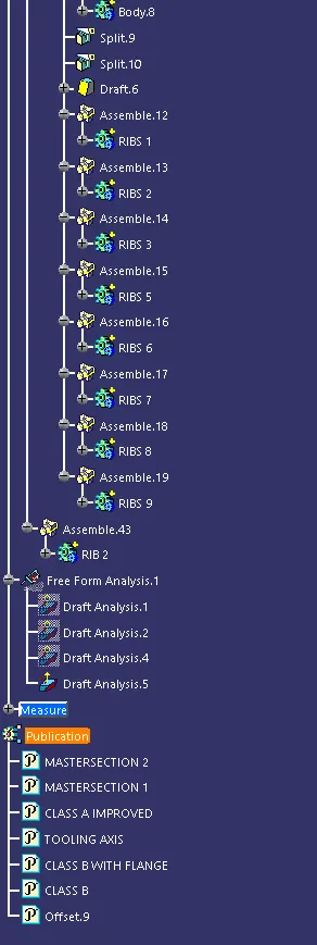
Tree Structure:
Result:
Front view
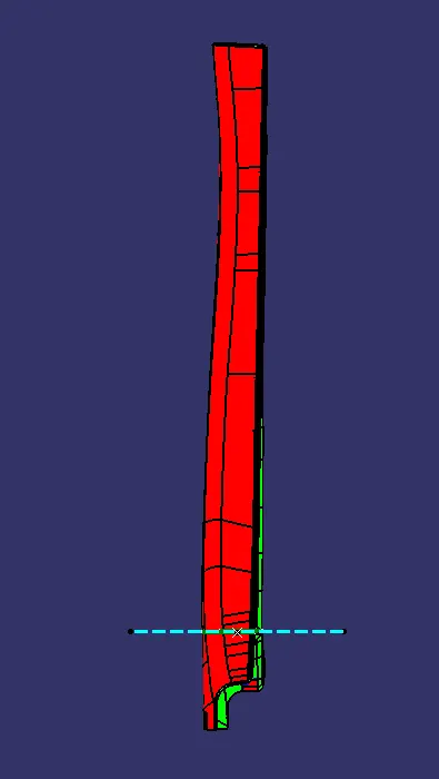
Side view
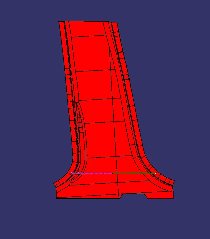
Top view
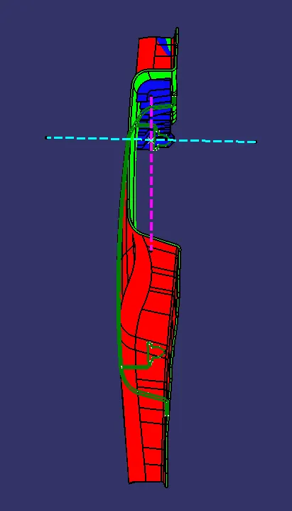
Google Drive Link: