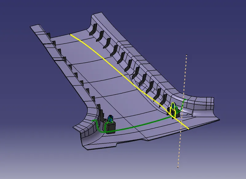
Week 9 - Project - Master Section Development
Aim –
Development of a Car B pillar cover, and making B – Side features as per given Master Section.
Introduction –
In the industry, when there is Designing of a new part for the car or Re – Designing the same, there are so many considerations which are taken care of with the help of Master Sections. This consists of very important information. On the basis of the Master section, the whole design is carried out.
Master Section –
Is a 2-D sketch (lines and curves) which is made by an Expert, and requires a very high skill level to create it. This consists of all the data like, Fixation, Packaging, Clearance (all the important placement distances), and Feasibility.
This all happens between Feasibility Check and Concept Validation, (Just before the New Product Development department takes place).
Methodology –
As discussed above, the master section takes care of various things and parameters, for this project we are having data of Fixation, we have given Class A surface as well as a Master Section with which we will be making a Close body as well as design the respective B Side features according to master sections. We also need to create tooling directions for the same.
Tooling Direction –
Tooling Direction/Tooling Axis is a Direction which defines how the Plastic will be made. It defines some of the most important parameters viz. 1. What will be the orientation of the part?
- How will it form?
Once this is done, a mold designer will be making Core and Cavity for the same part with respect to the main tooling direction.
Generally, it is practiced to make the tooling direction Vertical/Normal (90 degrees) to the surface/face. Which is the ideal condition. But in some cases due to undercuts or -ve drafts, tooling direction MIGHT change and might as well require a Side Core/Lifter axis
The extra features that we have created will also need to be created according to this main tooling direction. Which means it will be taking this tooling direction as a forming direction. Which are the B-Side features.
B – Side Features –
These are the features which we will have to make for the sake of connecting the part with the rest of the components, whether it be another part or fixation plane or etc. There are various features on this surface viz, Ribs, Screw Bosses, Dog houses, etc.
To start the modeling we will have to take a look at the master section and take some important parameters before actually making the part, this contains Inspection, Measurements and Features defined in it.
For us the master section we got has below shown details -
- Thickness of the part
- Dog house with a 4-Way locator on top of it.
- Radius
- Drafts.
- Flange
Consider the following image –
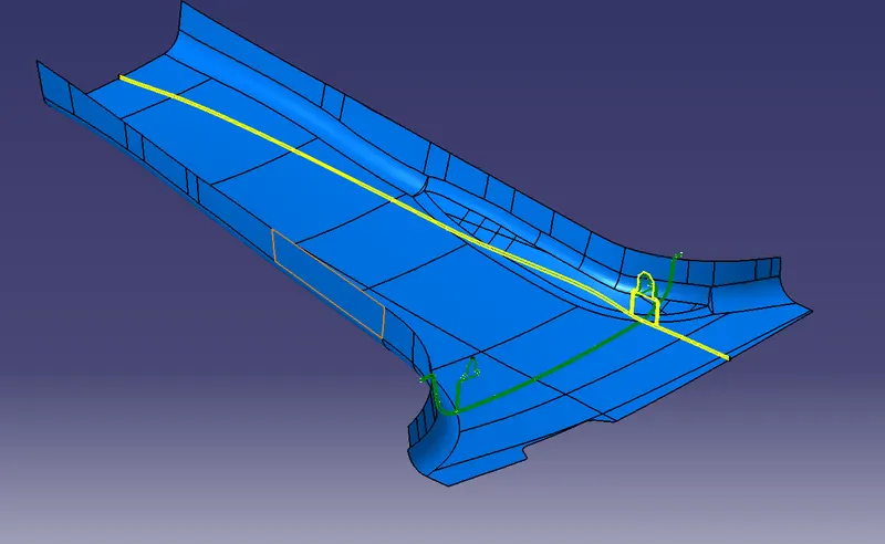
Before starting the process we need to make sure that the part is correct and not having any bad quality surfaces, or even not having any gaps in it, if any, then we need to take are of it, then verify the improvements with the Styling team. For our case, we can directly start since the Class A was already improved and was having good quality surfaces.
As usual, we will start by extracting the Class A but now since we have an extra feature that we need to take care of, which is the Flange, so need to make the Flanges on the Class A surface, then make a Class B, and then C then join everything to get a closed surface and at last, create the B side features.
Pre-Check draft analysis.
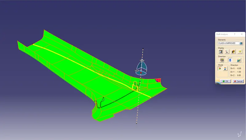
As it can be seen a small portion of the surface is having 0 degree draft but this much will be just fine, so we will ignore that portion and stick to the Tooling Axis which is normal to the surface.
Next we have to make the flanges,
For that we have taken the intersection of sweep that we made on the edges and then adjusted it with the maste rsection.
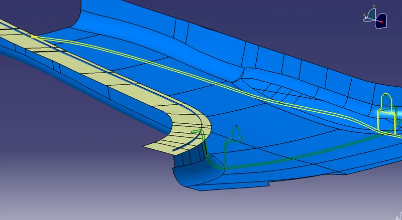
This was we have created two flanges and then created a Class B surface
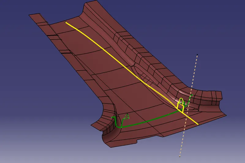
Followed by Class C and A trim,
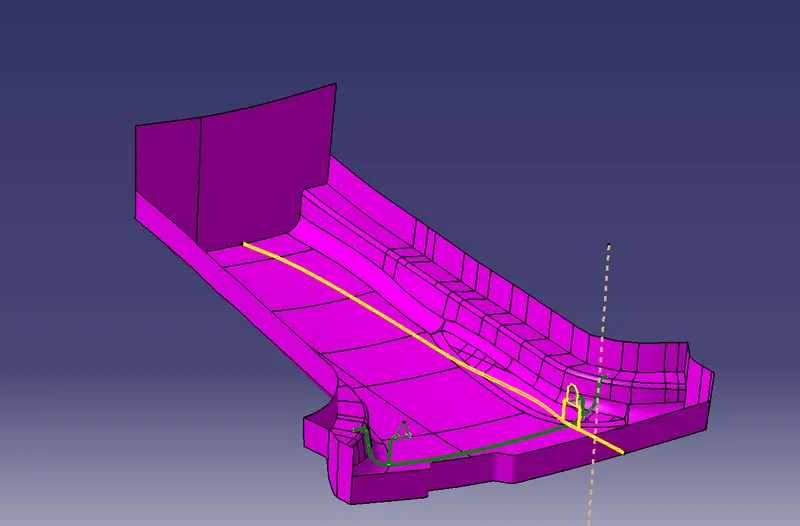
Until now, to create this output we need almost all the surfacing tools, namely, Sweep, Extract, Extrapolate, Multiple Extract, Line, Spline, Extrude Surface, Split, Trim, Multi-Section, Boundary, Point and Line definition, Line Split, Surface Split, Join, Curve Smooth, etc, all these feature are used to get this output.
Now we have a FINAL trim.
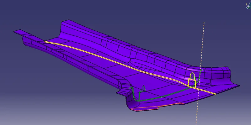
After this we make the B – Side Feature we start with the locators, now since we have two master section it is clear that the locator that we are having is a 4-Way Locator and not a 2 – Way locator, so we will design accordingly, there are several B Side features viz
Ribs which provides stiffness and strength to the part without overall thickness increment in the component, in addition to this, Ribs also also serves the purpose of FIXATION as well as LOCATION / ALIGNMENT for the part.
Screw Boss are used to connect the part via screwing medium, e.g. tow components will be screwed together but for that we will require some area for the screw to be locked on, and this area is the Screw Boss.
Once this is done both components can be screwed. However screw bosses are generally cylindrical, it doesn’t need tot tapped. Since the screw itself can create an impression on the plastic Boss. The basis function of the Dog House is to avoid SINK marks. This is needed when the Boss we are designing is thick enough to create a Sink defect. And to avoid this possibility we create a thick feature/ decrease the thickness where the base is connected, as shown in the figure.
Another thing is that we have a large distance from the base (B Surface) we cannot simply design the Boss all the way through, instead we give a Dog House to lift it, and Place the Boss on top of the Dog House.
The final feature of creating a dog is when we require the opposite or Perpendicular Boss with respect to the tooling Direction. Then we can Create a dog house respectively and place the Boss on top of it.
As per our master section there are no Heat stakes and screw bosses, so we will have to make the Locators and Dog Houses.
After following the above guidelines, we will be able to make a Dog House which follows design considerations and will not create any issues during Manufacturing. Same goes for the ribs.
Process –
After we have understood how to create dog house, we can now use the master sections and take reference sketches and use them for our benefit, since there are specific areas defined, we need to design the Dog House where the master section has shown us so, to do that we have to make sure the dog is follow the curvature of the B Surface, that is why we have extracted the surface and then created a Positional Sketch which is nothing but the master sections reference sketches. And then we are making our body.
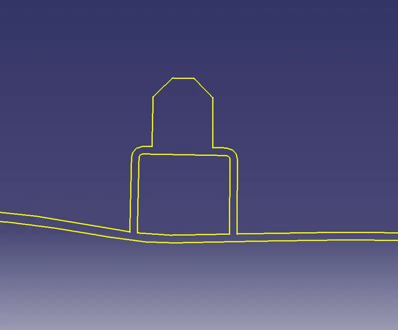
After this we can move to the part workbench and then thickened the extruded sketch, and cut the unnecessary extensions, with the help of SPLIT BODY command.
Now since Dog House is a feature which create an Undercut, we will have to make Separate Tooling Direction Which will be helping in that case. Also, not to mention we also need to give the drafts on all the faces and then finish the design with the fillets.
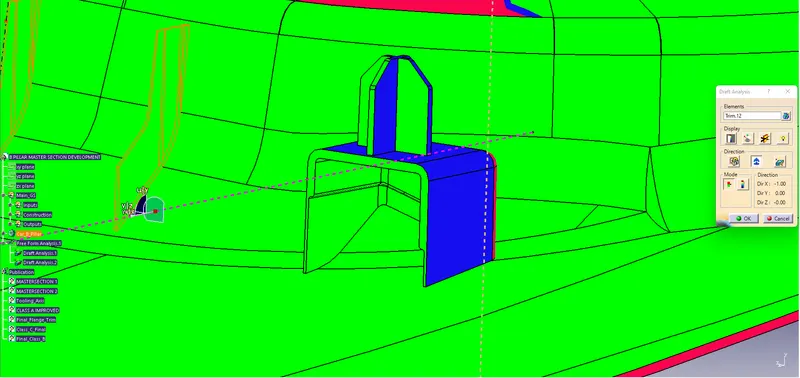
Consider the images of the Complete Dog house and Respective Draft Analysis.
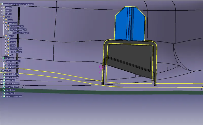
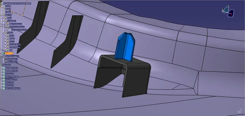
A simple yet careful solution we have done here, generally the dog house follows the curvature to the surface on which it is resting on but since the lower red line will result In undercut in the lifter direction and the part will not be formed so for that er have made the change and gave a straight math to the lifter/slider for ease of manufacturing as well as ease of part ejection.
Draft Analysis –
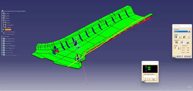
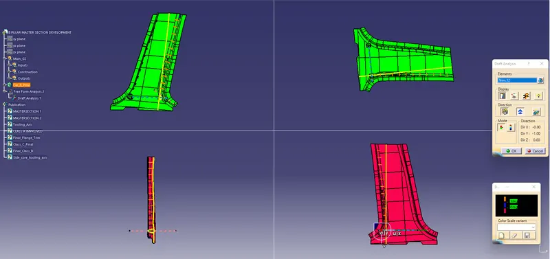
Ribs formation –
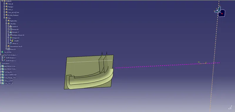
For ribs formation we have made sketches and points then used the line to make the extrudes after that, we also have to follow the curvature of the Surface we have trimmed the rib in such a way that I follow its curvature.
Then we have to give draft to it to finish things up. Consider the image shown below –
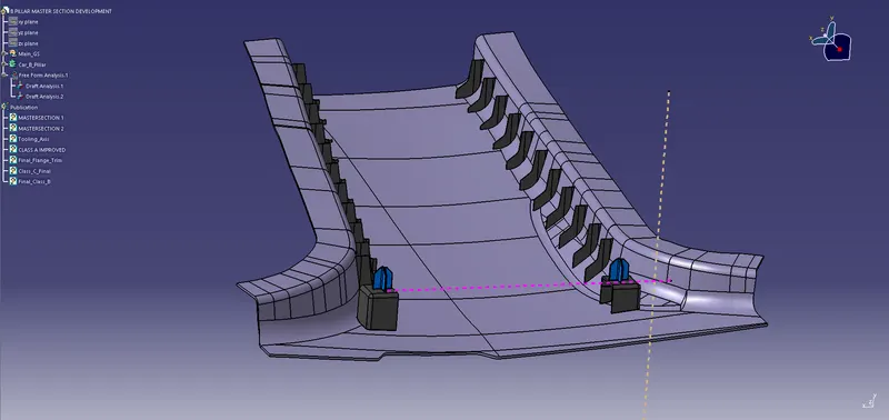
With the use of Translate body we have translated the Dog House and the Ribs and finally with the Boolean operations we have made the Solid.
Then we analyze the draft on the part. To finish things up.
Final Output –
For the tooling axis, we have made a point and made a line which is normal to the surface.
As we can see from above the parting line is on B Side which is good. But since it is an INNER PANEL, it will not be visible with the naked eye.