Week 8 - Challenge 1 - Draft Analysis on a Fan Cover
Draft Analysis:
The Draft Analysis command helps us detect if the part you drafted will be easily removed from the moulding process. This type of analysis is performed based on indentifying zones on the analyzed element where the deviation from the draft direction at any point, corresponds to the specified values.
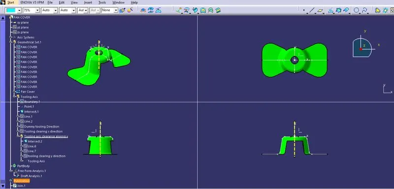
procedure to draft a fan cover :
- Join all the class A surfaces together to get a single component.
- Analyse the component.
- Check for optimum tooling direction.
- Find the best posiible tooling axis for the component component.
Creating tooling Axis:
- insert a Geometrical set
- Extraact the component boundary using the boundary command.
- Create a point at the center of the Z axis of the component, In this case the inner circle/ hole will be used as reference to create the point.
- Construct an axis system at the input point
- Next create an intersect along XZ plane and then select the class A surface.This will give an outline of the component along X-Z plane.
- Create a dummy line along axis point in Z direction
- Construct the tangent lines with reference to the intersect boundary line at both sides of the axis system .
Creating The Tooling Axis For the Fan cover:
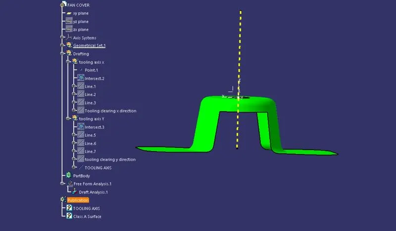
- Next we create a bisecting line, here both the tangent lines are taken as inputs along with the point for axis creation and then choose the direction of construction .Hence we get a tooling axis line clearing along X direction
- Insert another geometrical set ( Tooling axis Clearance along Y)
- Create another intersect along Y-Z plane and select the join of fan cover. we will get a boundary line of the component along Y-Z plane.
- create 2 tangent lines with reference to the intersect formed.
- Then create a bisecting line with the 2 tangent lines and point used to create the axis sysstem. Hence we will get a Tooling axis line clearing along Y Plane.
- finally we need to create a line bisecting both the Tooling axis line Clearing X and Y , In order to get the main tooling axis of the component.
- Publish The tooling axis and the component (join 1= fan cover).
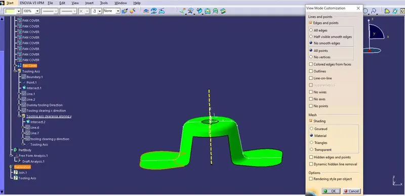
Draft Feature Analysis: - Select the quick analysis mode.
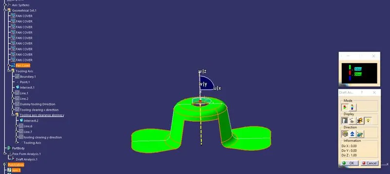
- Place the compass coincident to the tooling axis created in z direction and lock the axis .
- Then we choose the "show colour scale" to check if the part drafted will be easily removed from the core and cavity of the moulding process.
- Next using the "analysis under running point", check the value of the draft and make corrections accordingly.
- For the quick Analysis mode , when picking the surface with the colour scale output we will get 3 colours Green , red and blue , these colours can be changed manually if needed.
- The minimum angle of draft for an industry drafting component can be at a value of 3 degrees
- Hence red is the starting colour with 0 degree draft angle and green indicates 2 degree draft at the start and i have changed it to 3 degrees and hence the entire draft angle from the tooling axis of the component gets set to 3 degrees and then click ok after the analysis is done.
- This type of analysis is performed based on indentifying zones on the analyzed element where the deviation from the draft direction at any point, corresponds to the specified values.