Week 9 - Project - Master Section Development
Master Section design
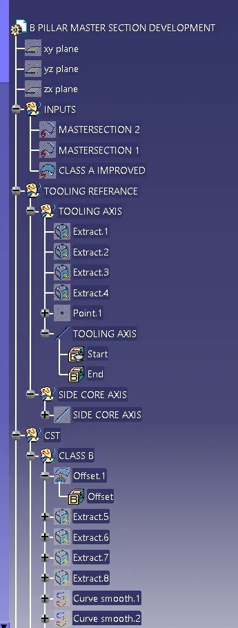
creation of tooling axis:
select any master section and extract the two lines.
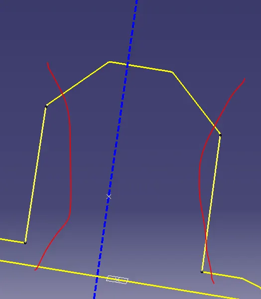
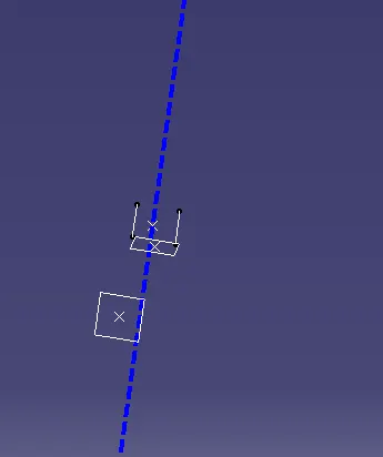
create a point between the two lines and darw a bisecting line at the point.
Creation of class B:
Offset the class A surface by 2mm.
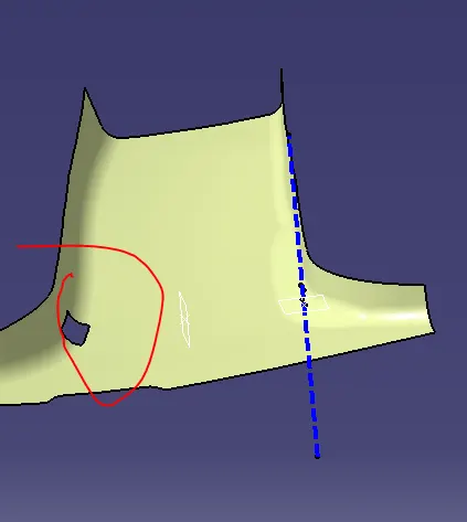
A small patch is not formed. so for that patch Extract the boundaries of the patch.
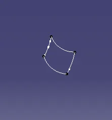
Use multi-section solid to get the patch filled.
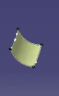
join the multi-section solid with the offset surface to get the B surface.
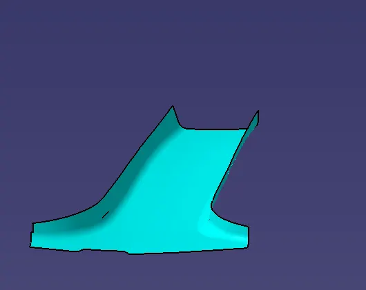
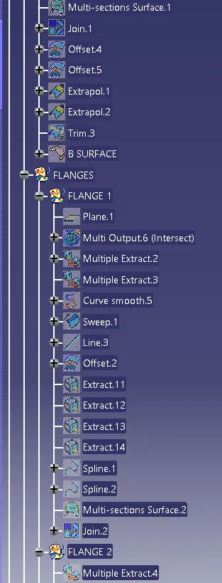
Creation of Flanges for A surface:
Create a plane and make intersect with that plane.
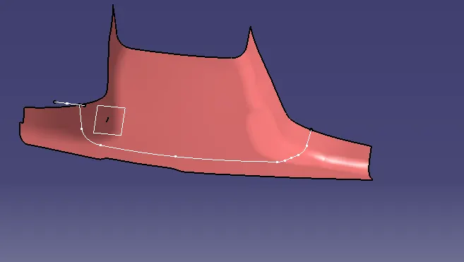
multi extract the boundary of A surface.
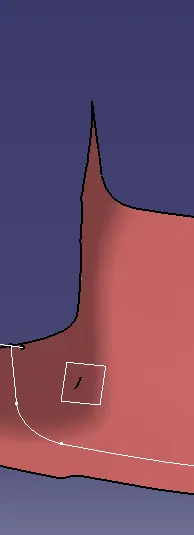
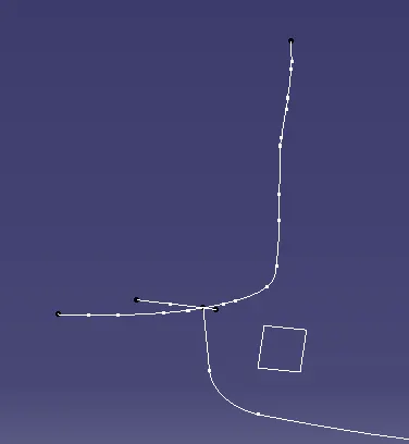
extract the class A surface for reference to sweep the boundary extracted.
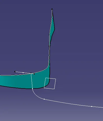
use sweep giving the surface as reference.
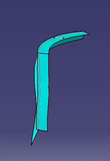
make an offet of 2mm to get the flange for A surface.

There is a small patch left on which we have to work on. Extract the boundary and surface for reference.
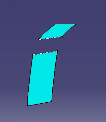
create a spline curve between the boundary extracts.
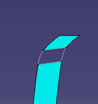
use multi section surface to get filled.

make a join with the offset.

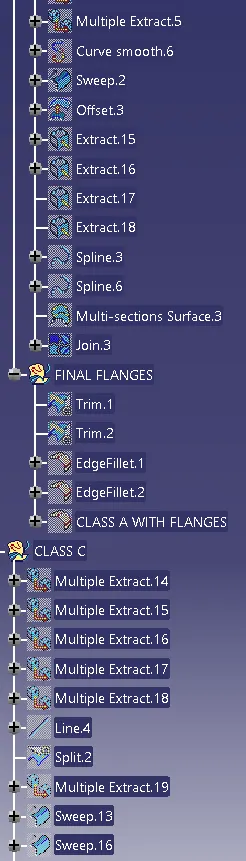
In the similar way following same rules design the other side of the flanges.
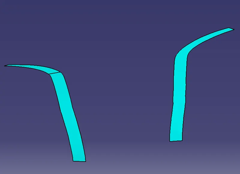
make trims with the improved class A surface .
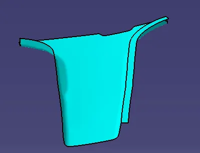
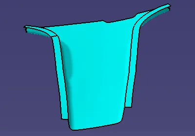
finally giving the fillets required.
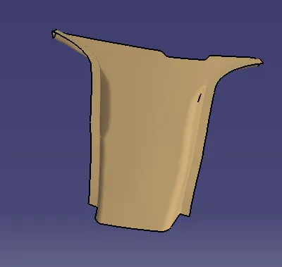
In similar way the class B is also trimmed and required fillets are given.
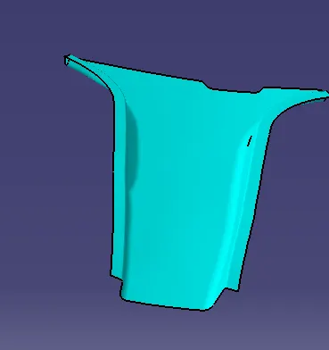
Creation of C surface:
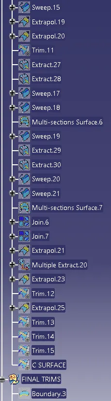
Extract the Class A surface boundaries.
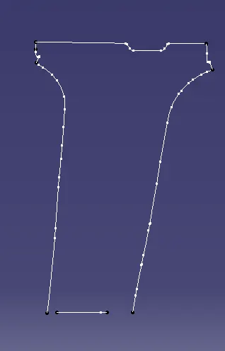
Small patch of class A surface to to be splited by using the line.
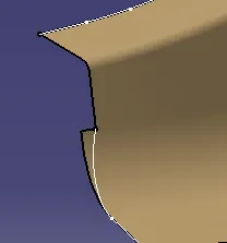
sweep the boundaries using tooling axis as draft direction.
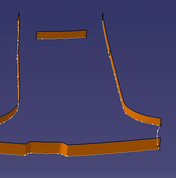
extrapolate the suface and class A surface and trim them.
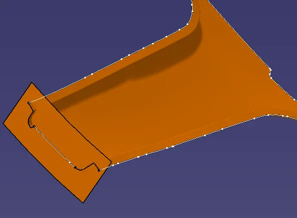
extract the small surface and make sweep with the draft direction.
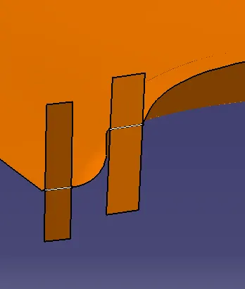
make multi section solid between the sweeps.
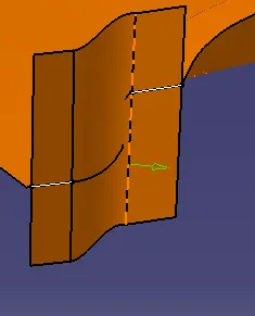
similarly on the other side
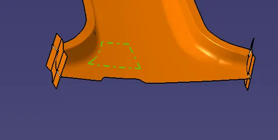
extrapolate the areas which cause problem for trimming and do the final trims to get the c surface.
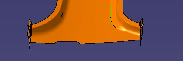
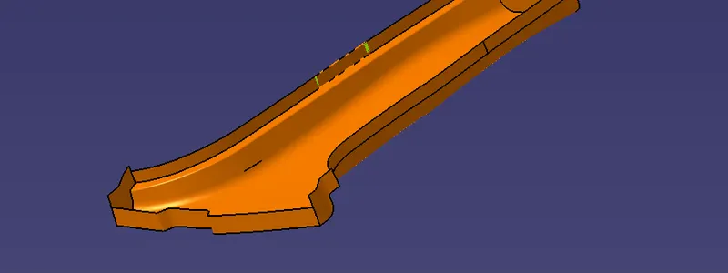
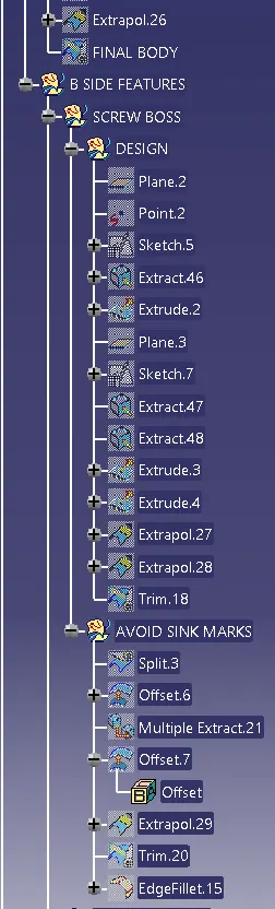
create the boundary for class A surface and extrapolate to get the final body.
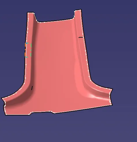
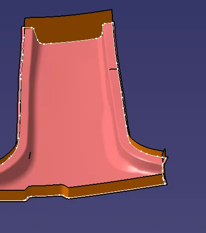
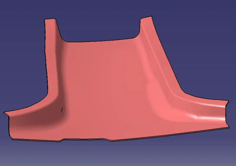
trim with the C surafce to get the final body.
B side features:
Project the master section 1 and isolate to get the sketch.
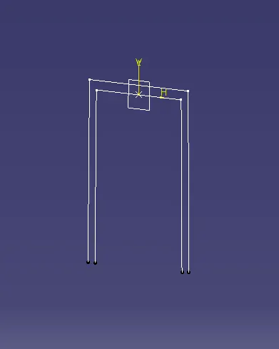
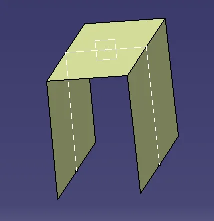
extract the sketch and extrude as shown below.
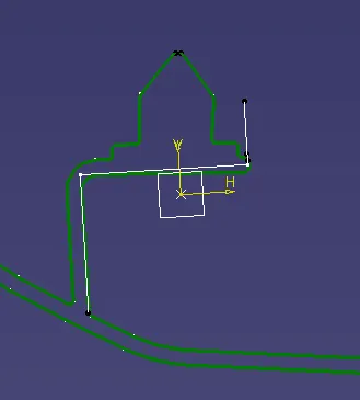
project the master section 2 and draw the sketch.
extract the limiting faces for the dog house and extrude them.
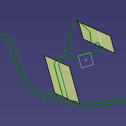
Extrapolate and trim with the first extrude.
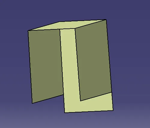
give the thickness of 2mm.
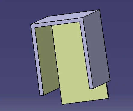
make split with the front limiting surface.
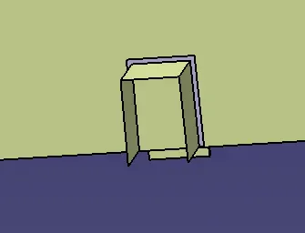
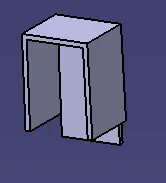
give the draft with reference to the tooling axis and fillets required.
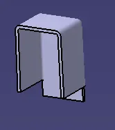
Creation of four way locator:
project the master section 1 and make it in to reference elements.
Draw the lines connecting the refereence lines.
extrude them with the thickness of 1.5mm.
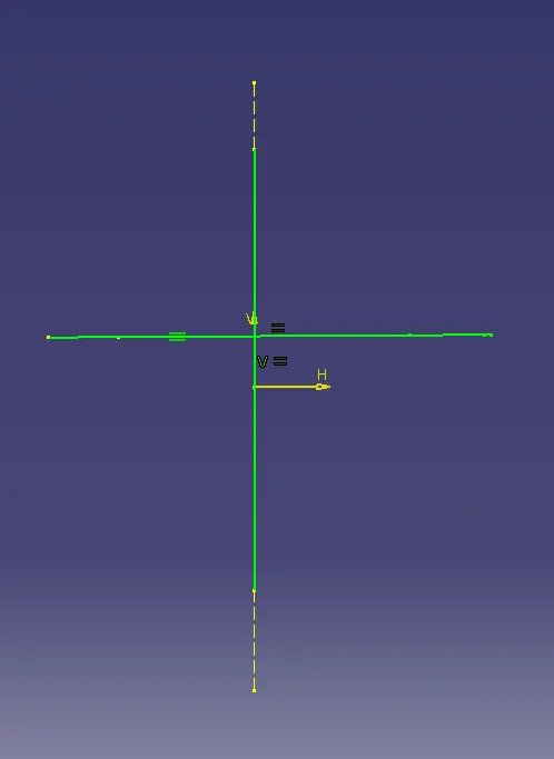
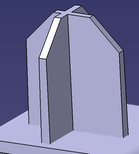
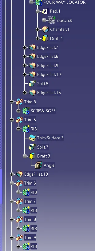
Give the draft angle with reference to the tooling direction and union trim with the dog house and give the fillets required.
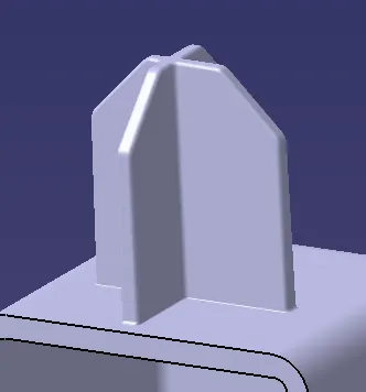
copy and paste as a link on the main body as to get the other side.
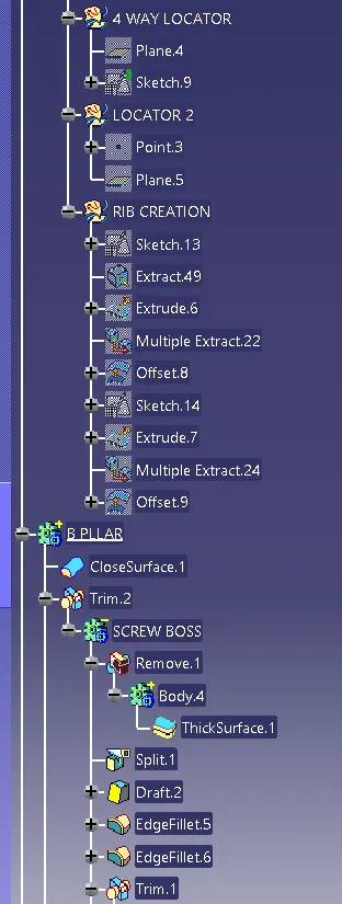
Make union trim with the B Pillar main body to avoid the minimal errof for designing the sink marks.
To avoid the sink marks offset the split.
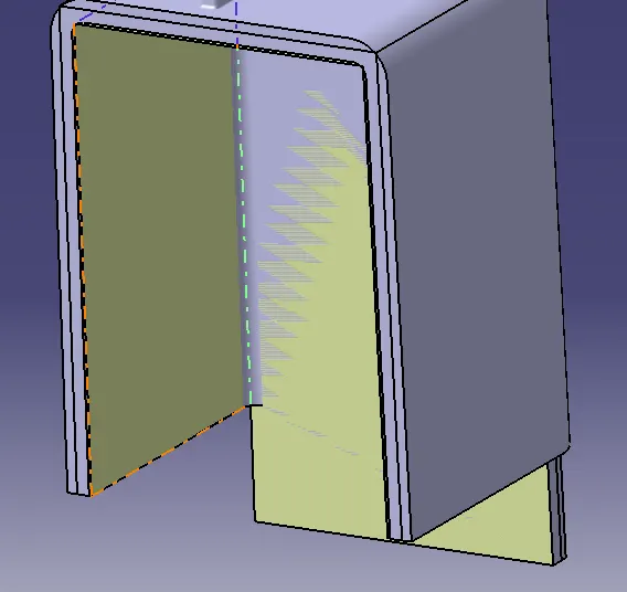
extract localy the b surface and offset it with 5mm.
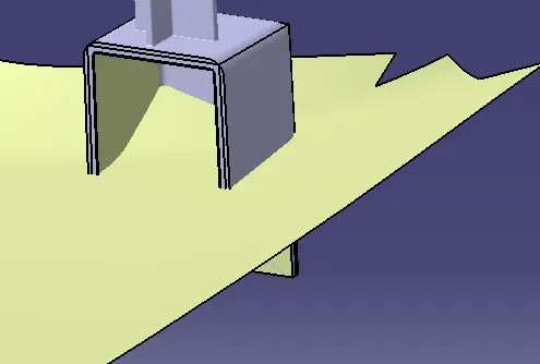
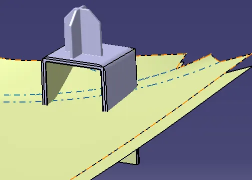
make trim with the offset surface.
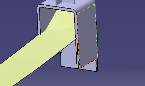
split it with the part body.
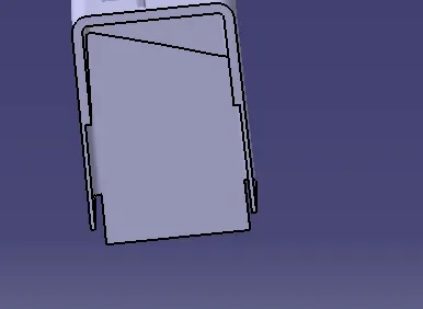
As a result the operations which are done in the parent will result in the child which was mirrored.
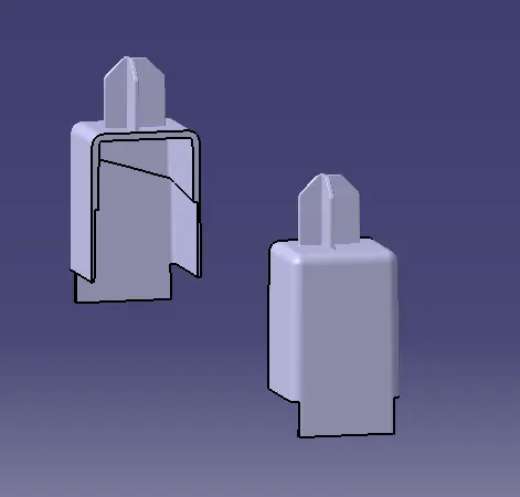
Rib Creation:
Draw a line and make extrude with thick ness of 0.8mm.
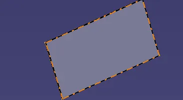
Extract the B surface locally and offset it to 10mm.
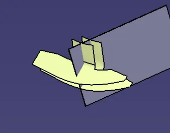
split it with the offsett.
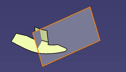
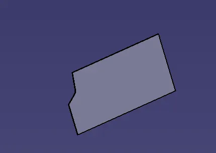
make unin trim with the B pillar and give the fillets.
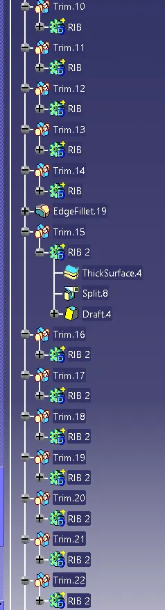
Copy the body and paste as a link in the main body and make translate to get the remaining ribs.
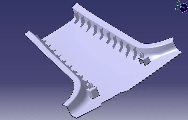
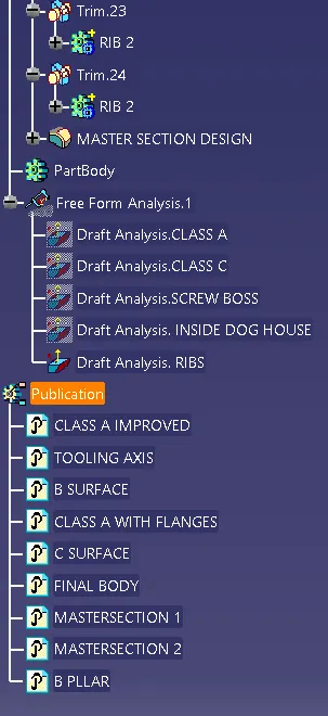
Draft Analysis:
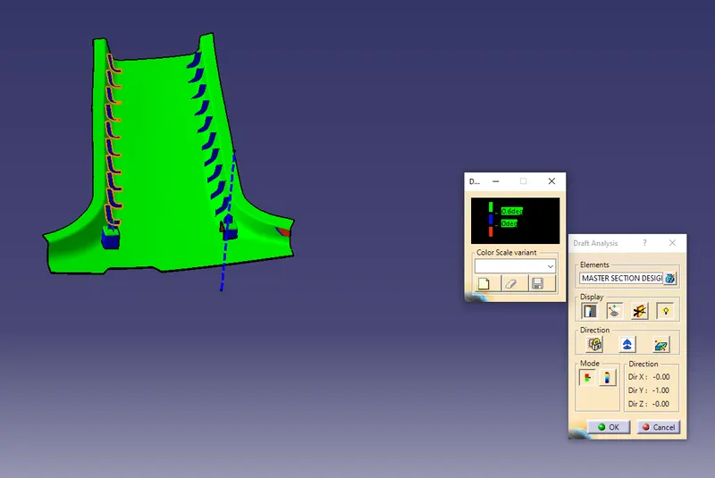
For class A :
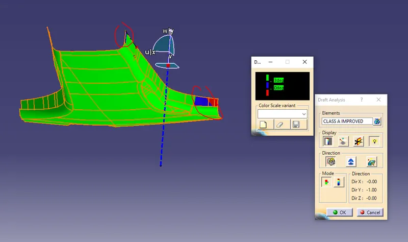
small patches are not drafted but they wont cause much problem in the designing.
Draft analysis for final body: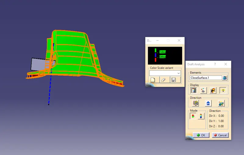
Draft analysis for B pillar: