Week 9 - Project - Master Section Development
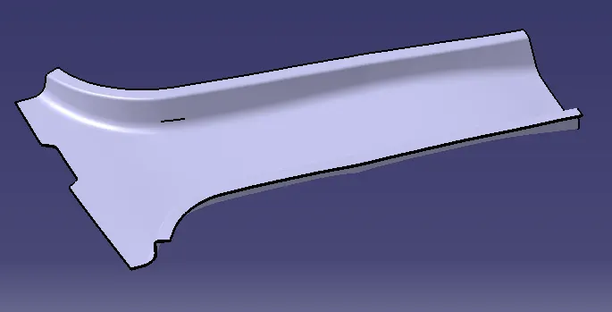
Aim: The aim of this project to develop a closed surface model by using of your section and developed beside feature for locked the degree of freedom of component. Hear we can use B pillar master section providing by the OEM standard.
Abstract: The report details about the design life in automotive industry with a practical model of working model of B pillar cover on the B pillar car of interior. The report explains the steps followed in creating axis followed by detail methods in creating B surface, class C surface and to closed body.The attachment feature creation is also reported by designing the details guidlinesabd final analysis of draft to prevent the failure and improve the feasibility of manufacturing the part in plastic injection moulding.
CLASS A SURFACE: Class-A is a term used in specifically in automotive design. It describes the final production surface data for the aesthetic parts of the car.
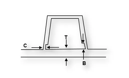
CLASS B SURFACE: This surface is created by taking the offset fom the class A surface and it is the surface on which all the mountings and ribs are created
CLASS C SURFACE: It is the surface which joins class A and class B together
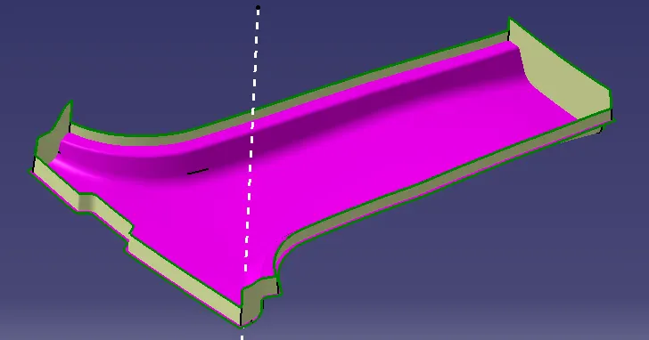
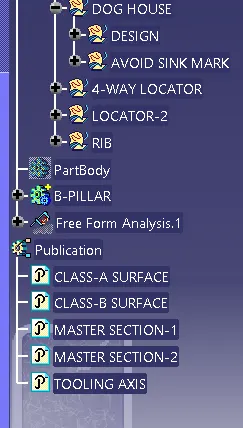
TOOLING AXIS: It is the direction in which core and cavity opens & closes
PROCEDURE:
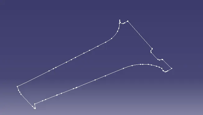
- check the continuity of class A surface and ensure that it was properly joined without any discontinuity.this can be done by using join or boundary comand in CATIA v5
- Extracting the boundary of given class A surface and we also check continuity visually.
- we have to give even wall thickness to avoid flow lines after the manufacturing process
The Procedure followed in creation of the plastic new product design are
- Tooling axis
- B surface creation
- C surface creation
- B side feature creation
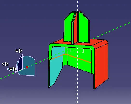
- Side core axis creation
- Draft analysis
Tooling axis
- to decide the tooling axis direction by analyzing model visually to see which direction is most suitable for tooling axis
- the given model they are two tooling direction one is main tooling axis and other was lifter side is used to eject the parts during the injection moulding
- lifter axis is used because the attachment feature is bounded by closed walls
- Thus, tooling direction determine mould separation and also becomes vital in developing the plastic product which is drafted to desire nominal angle for feasible clearance and ejection of final product from the mould.
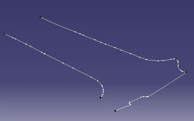
Extract the sides of the master section and extract the sides on other side of the master section and create bisector for these extract as shown in the fig
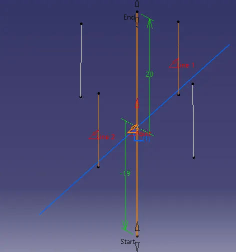
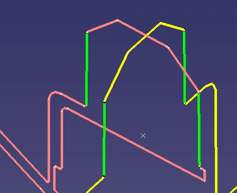
bisection of these bisectors is the actual tooling axis that was created
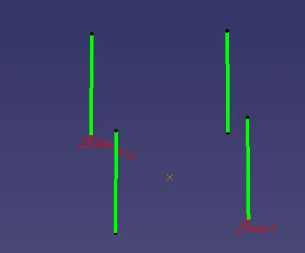
check the draft analysis for the given classA surface
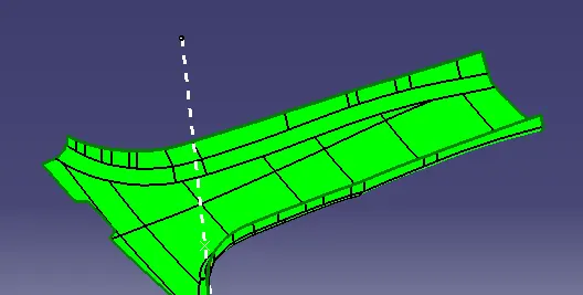
CLASS B SURFACE
To create the class B surface select the class A surface and offset it to 2mm
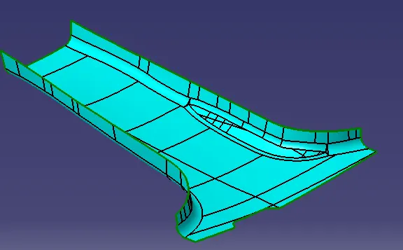
FLANGES
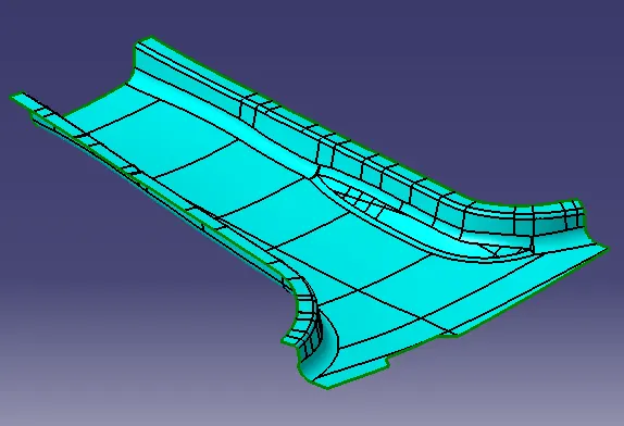
- From the master section it can be observed that b-pillar is having flange but the given class a surface doesnt having the flange
- to create a flange we need to extract the bondaries of class A and class B surfaces and the surfaces which are attached to te boundary need to be extracted which acts as a refering surface for the flange while sweeping
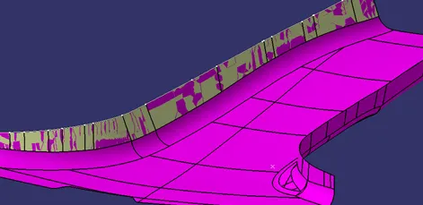
- sweep the bondary with ref to the surface and given correct angle such that flange was aligned with the master section and then offset it to 2mm
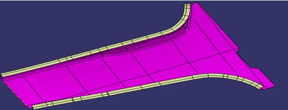
- join the sweep surface with the class A surface and the offset surface with the class B surface
CLASS-C SURFACE
- To create the class C surface ,first extract the boundaries of the class A surface and sweep with help of tooling axis and give the draft angle as 3deg
Final trims
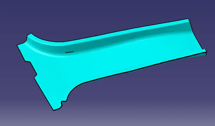
- Trim class B surface and class c surface And then trim the class A with the above enclosed surface
- Use the close surface feature,the final closed surface is coverted to solid body
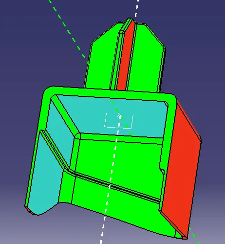
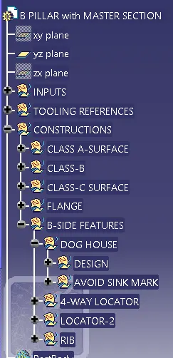
DOG HOUSE : Dog house is a feature helps you to avoid sink marks
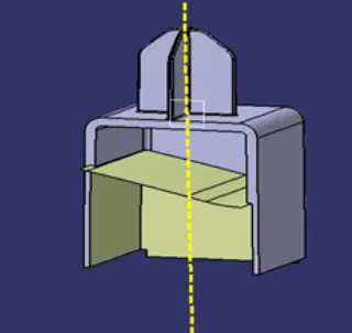
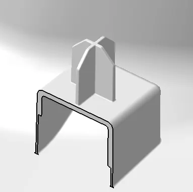
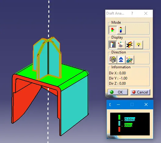
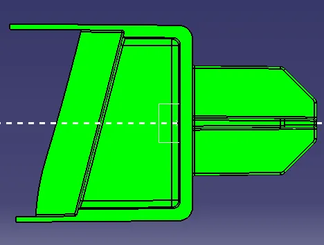
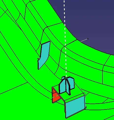
DRAFT ANALYSIS FOR DOG HOUSE and SCREW BOSS
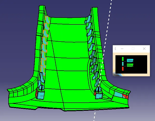
SIDE CORE AXIS
RIBS
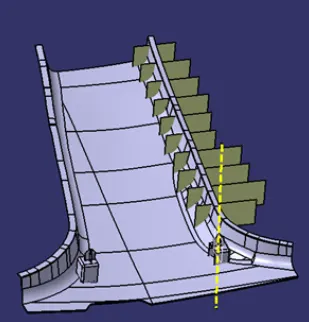
- Ribs created to increase the strength of your part to increase the thickness of its walls. Because less material is required. Ribs can be a much more effective solution as well.
- To create a rib ,we first need to draw a straight line in the sketcher workbench. Afrer Creating the line, extrude it and pad it.
- We need to create multiple ribs which are 50 mm apart, first go to the class A/B surface and extract the edge where the flange is connected to the main body. Now using this boundaries create the repetition points which are at 50 mm apart from each other.
- Now copy the rib which we created and paste it in the main tree structure. Using the translate option the copied rib can be mode from 1 point to another point. Repeat the above steps for creating all the ribs and position it on the main tree that we are created using the repetition point section .
- Offset the class B surface to 10mm and trim the ribs with it removing the access portion of the ribs and give a draft of 0.3 to the ribs.
- Create the ribs another side as well.Once all the engineering features are created, add it /trim it / with the main body.B pillar and give appropriate fillet value to all parts of the body.
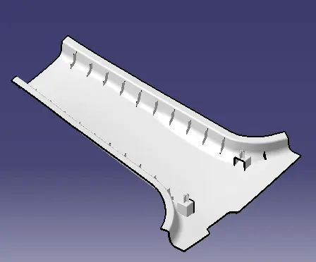
3D-MODEL
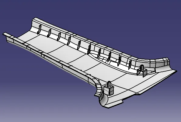
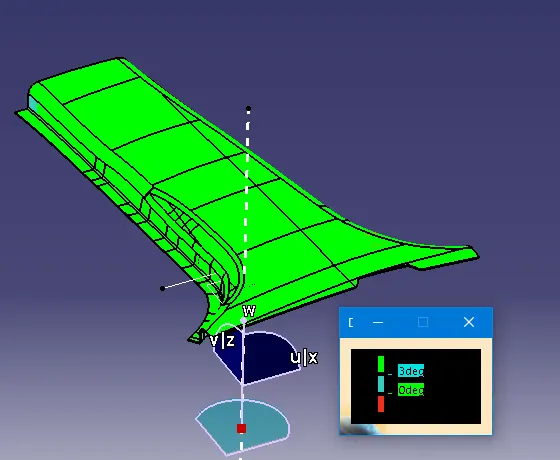
DRAFT ANALYSIS
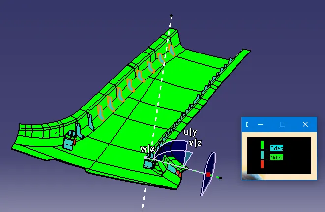
- Go to INSERT-ANALYSIS-FEATURE DRAFT ANALYSIS and move the compass towards the tooling axis and change the range to 3
- use the compass to align it with tooling axis and check the draft anlysis by clicking on the surface
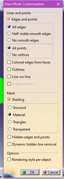
- change the view mode customization to material mode
-
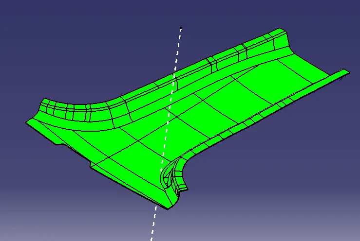
TOOLING AXIS
SIDE CORE AXIS
PART BODY
CONCLUSION
B PILLAR component with engineering features using the master section and claas A and class B created and draft analysis have also been performed for the created body