Week 9 - Project - Master Section Development
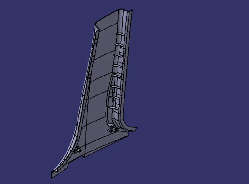
AIM: The objective of this project is to design a B Pillar and the attachment features with CLASS A Surface and the Master Sections as the input by following the OEM standards.
MASTER SECTIONS
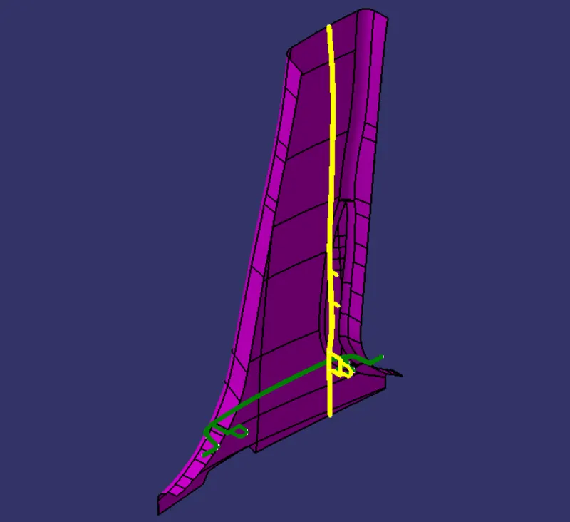
Master sections are the guides for design requirements which decide the component packaging after technical (Styling, Concept or Class-A) surfaces.
OBJECTIVES
- To create the Tooling Axis in the best possible direction.
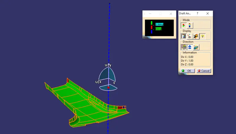
- Draft Analysis on the CLASS A Surface and the Final Plastic Component.
- Creation of CLASS B and CLASS C Surface.
- To make a closed surface with a thickness of 2mm.
- To create the attachment features on the B Side.
PROCEDURE FOR DRAFT ANALYSIS
- First check the connectivity of the given CLASS A Surface by using the Join or the Boundary command to ensure there is no gap in between.
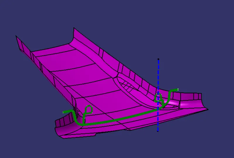
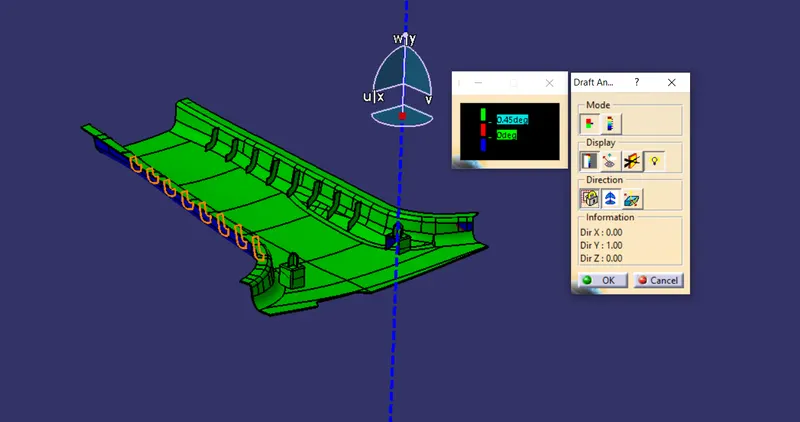
- Analyze the best possible tooling axis for the given component.
- Create the main tooling axis, by creating the midpoint between the master sections .
CREATION OF B SURFACE
- Offset the CLASS A Surface with a thickness of 2mm following the master sections.
- Check for the irregular patches in the Offseted surface , if found some then use Multi Section to to form the required shape.
- Extrapolate the required patches for trimming with the CLASS C Surfaces.
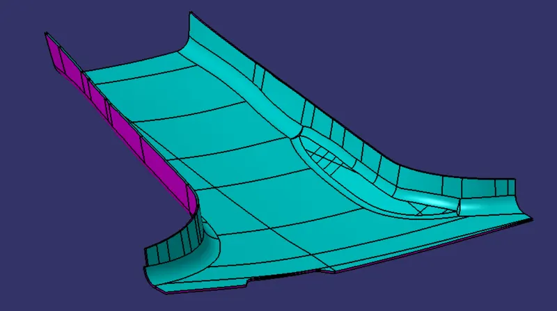
CREATION OF C SURFACE
- These are the surfaces which join the class a surface with class b surface , leading to the formation of closed surfaces.
- Create boundaries of Class A Surface, and sweep them along the Tooling Axis with a draft of 3 Deg.
- The C surface must be drafted outward to avoid the parting line along the CLASS A Surface.
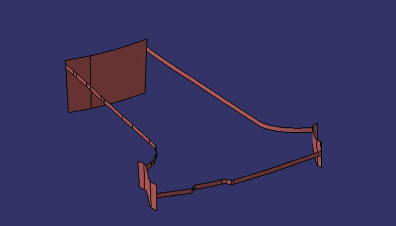
CLASS A +CLASS C
To ensure there is no gap between the CLASS A and CLASS C surface we have joined the two surfaces
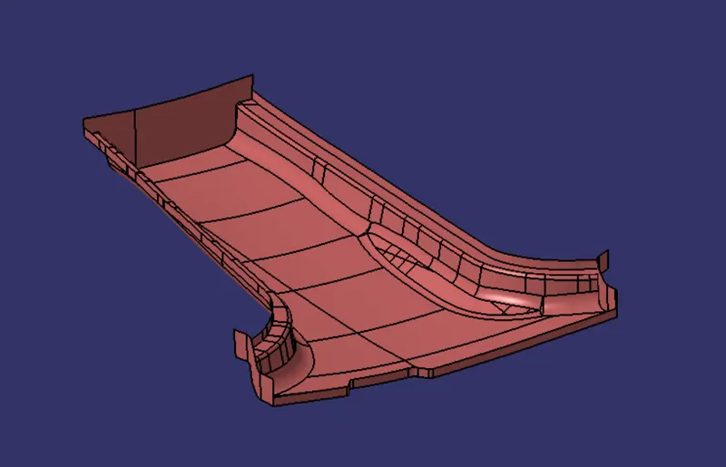
FINAL TRIMS
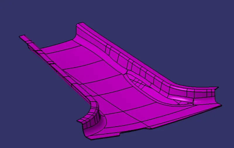
CLOSED SURFACE
The final trim is now closed using the closed surface command in the part workbench to obtain the final solid component.
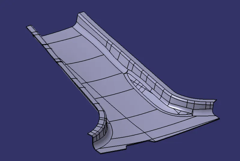
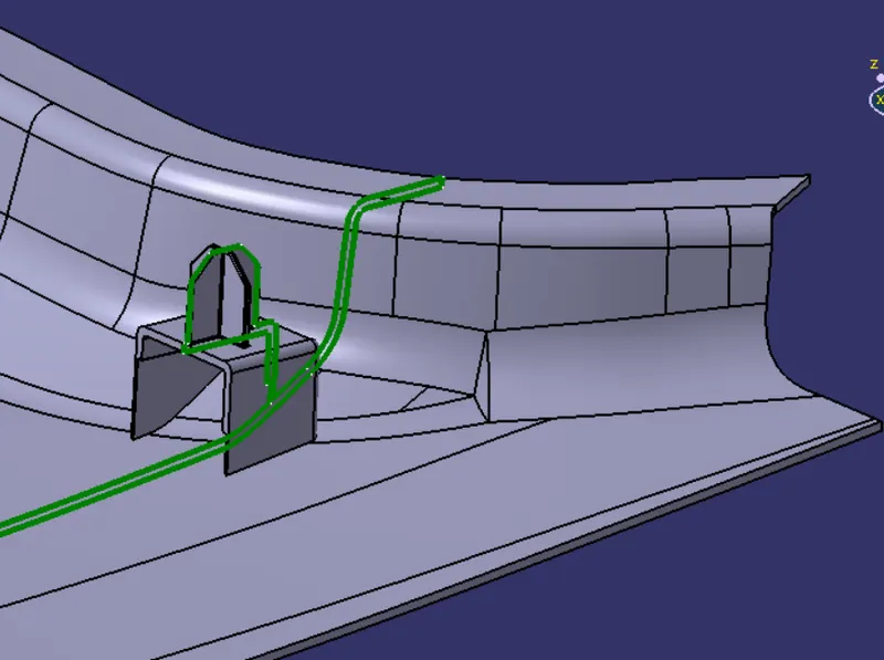
DOG HOUSE AND 4 WAY LOCATORS
DOG HOUSE
Dog house is an engineering feature used in plastic components. Dog houses are used as supporting features. Sometimes other engineering features like snaps, screw boss, locators etc. are mounted on them to increase their strength.
Reasons which facilitates the use of Dog House
- To avoid sink marks on the high quality surface.
- To solve the length factor in case of screw boss.
- To make a screw boss in the direction perpendicular to the tooling axis.
DESIGN CONSIDERATIONS FOR DOG HOUSE
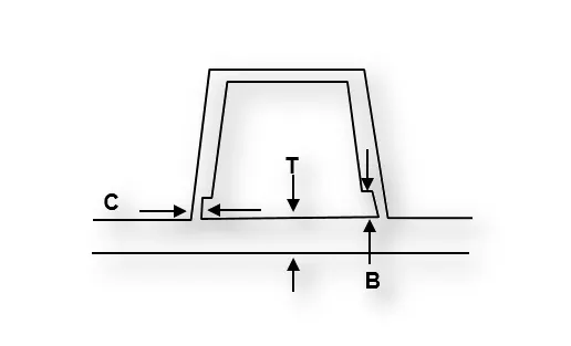
- "C" is where the doghouse contacts the backside of the surface.
- Doghouse wall thickness at the intersection of the part wall ( C ) should be 40% or less than the main wall stock ( T ).
- Height of ( B ) should be between 3.0 – 6.0 mm.
- Minimum height should be 6mm, less than 6mm causes weak steal condition.
- Draft should be minimum 1.5 Deg.
RIBS
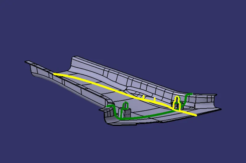
Ribs are indispensable functional structures on many plastic parts. It can effectively improve the rigidity and strength of plastic parts.By using ribs, it is not necessary to greatly increase the wall thickness of the plastic parts, Ribs are generally designed on the non-appearing surface of the plastic part, and its direction is as close as possible to the flow direction of plastic melt filling. Ribs should neither be too long nor too thick, otherwise, it will increase the difficulty of injection molding, causing problems such as voids and sink marks on the back.
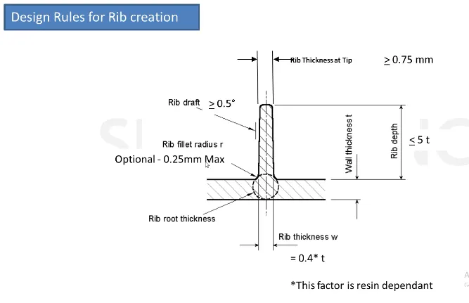
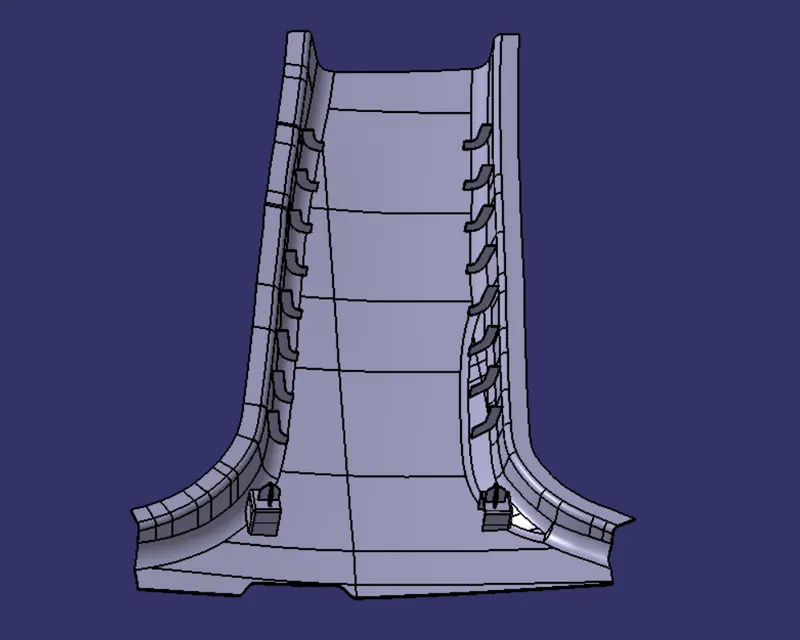
The ribs should be 50mm apart as per the master sections.
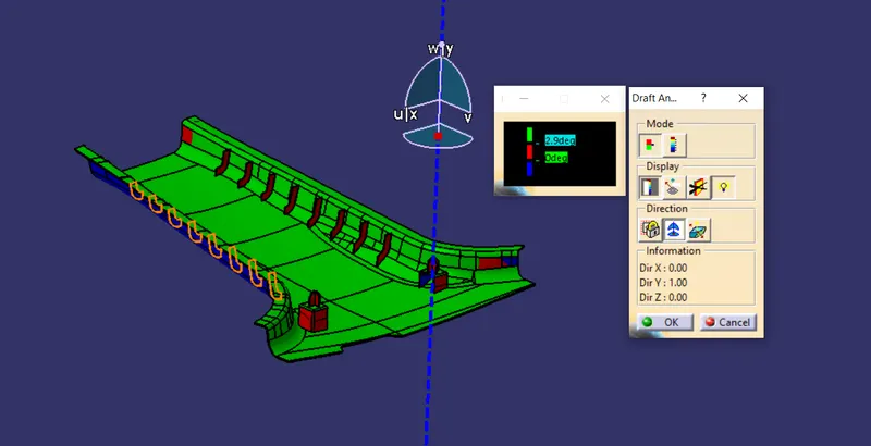
DRAFT ANALYSIS ALONG THE MAIN TOOLING AXIS
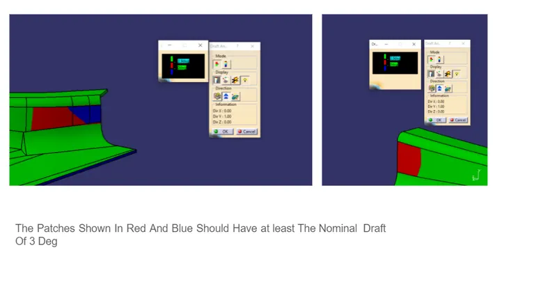
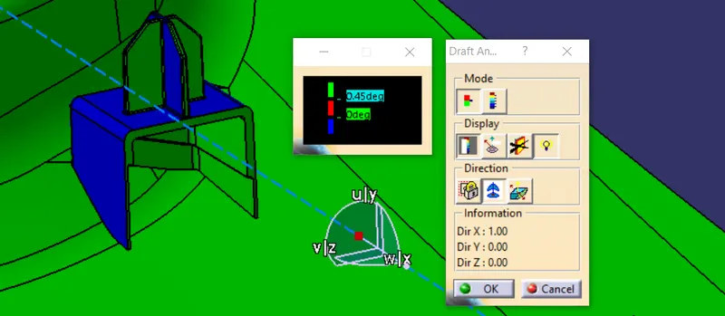
DRAFT ALONG THE LIFTER AXIS
FINAL COMPONENT