Week 8 - Challenge 3 - Switch Bezel Design
AIM: To create a base bracket component through the given CLASS A Surface and to perform the draft analysis on the component.
OBJECTIVES
- To create the Tooling Axis in the best possible direction.
- Draft Analysis on the CLASS A Surface and the Final Plastic Component.
- Creation of CLASS B and CLASS C Surface.
CLASS A Surface
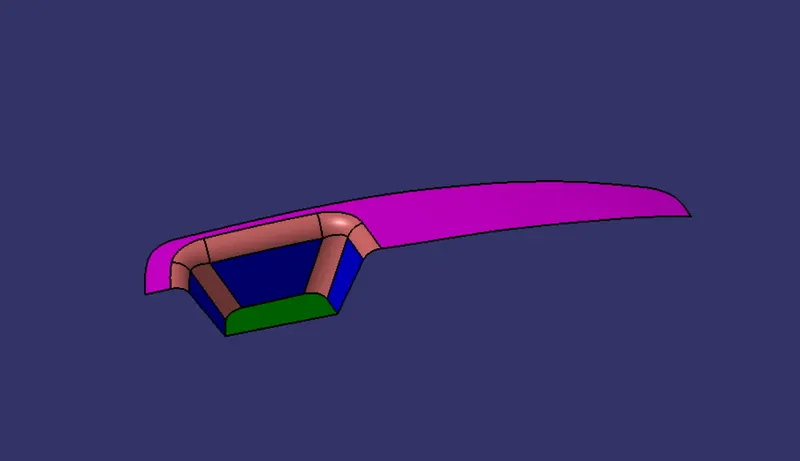
PROCEDURE FOR DRAFT ANALYSIS
- First check the connectivity of the given CLASS A Surface by using the Join or the Boundary command to ensure there is no gap in between.
- Analyze the best possible tooling axis for the given component.
- Proceed with the TOOLING AXIS with the New Axis System.
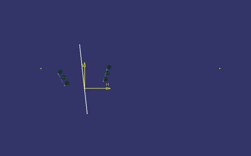
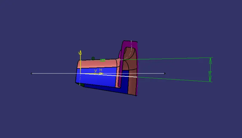
Bisecting Line: The bisecting line is the line splitting in two equal parts the angle between these two lines.
Main Tooling Axis
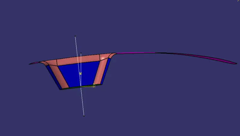
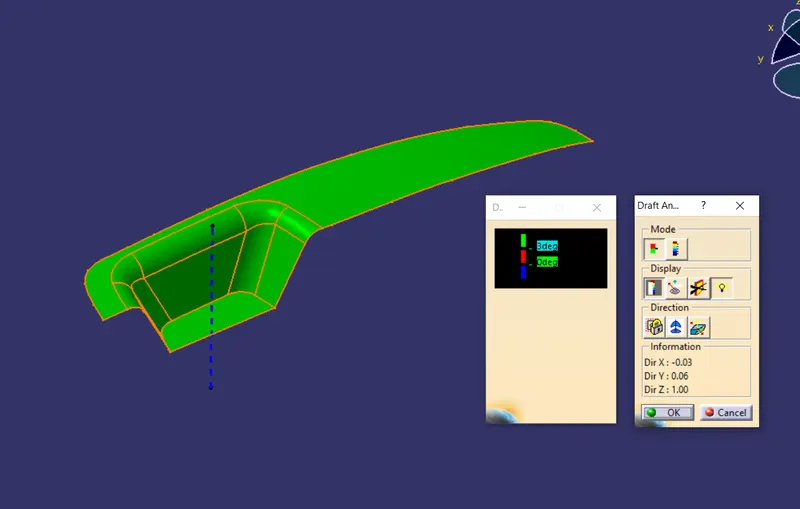
Draft Analysis On CLASS A Surface
- Select the Material Mode in the Toolbar for Draft Analysis
- Add the Compass to the main Tooling axis and lock the tooling position.
- Click on the Surface for the output of the analysis.
CREATION OF B SURFACE
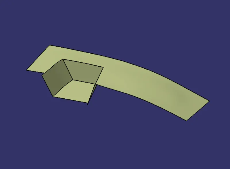
- First extract the surface from the given CLASS A Surface and untrimmed them to obtain the Parent Surface
- After untriming , all the surfaces are then extrapolated.
- Offset the untrimmed surfaces to the required thickness i.e 2.5mm
- At last trim the offset surfaces to obtain the required final trim.
CREATION OF CLASS C
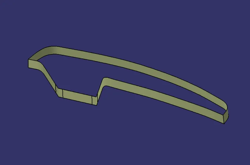
- For creating a CLASS C surface we extracted the boundaries of the CLASS A using Multiple Extract.
- These extracted boundaries are now swept along the Main Tooling Axis with 3 deg draft.
CLASS A +CLASS C
To ensure there is no gap between the CLASS A and CLASS C surface we have joined the two surfaces.
FINAL TRIMS
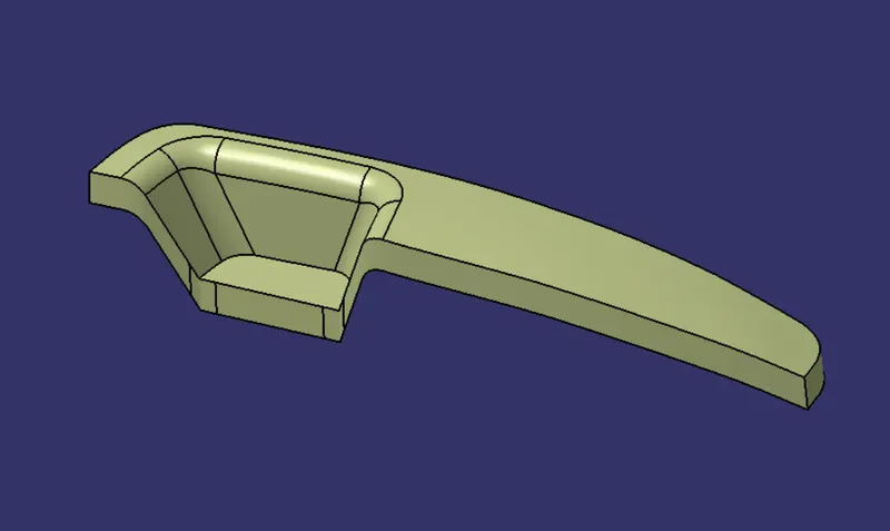
The joined CLASS C surface is now trimmed with the CLASS B Surface to obtain the final trim.
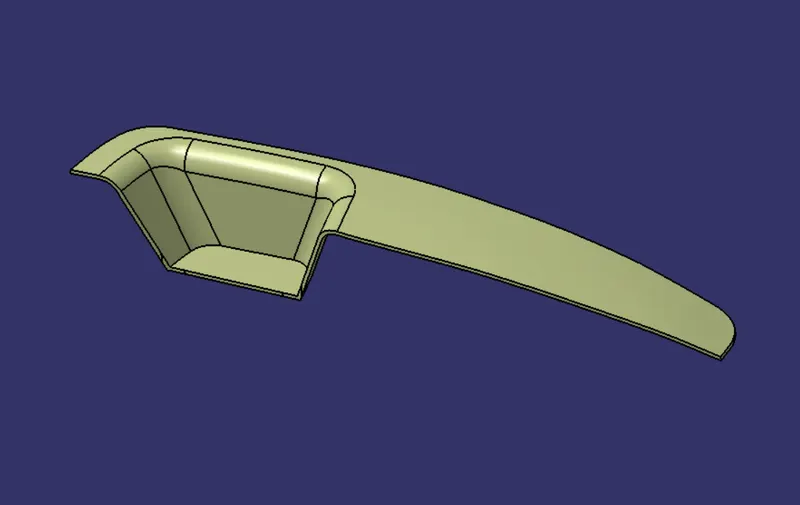
CLOSED SURFACE
The final trim is now closed using the closed surface command in the part workbench to obtain the final solid component.
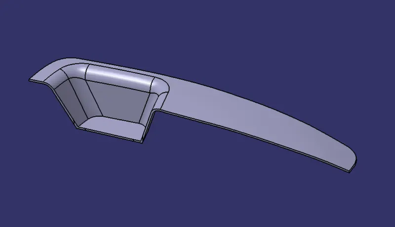
DRAFT ANALYSIS ON THE FINAL COMPONENT
The following results were obtained in draft analysis of the final component.
ISOMETRIC VIEW
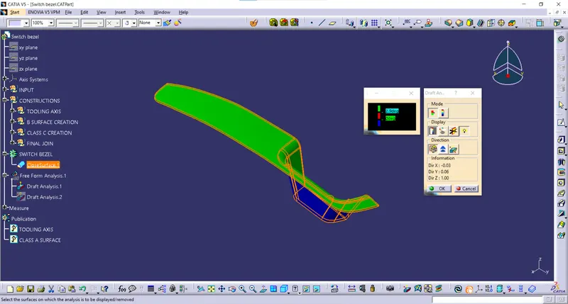
SIDE VIEW
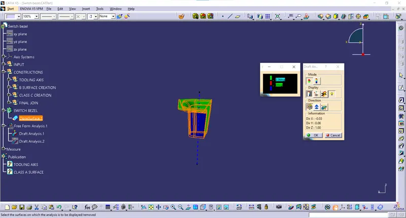
FRONT VIEW
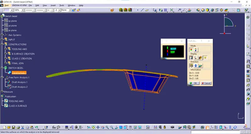
TOP VIEW
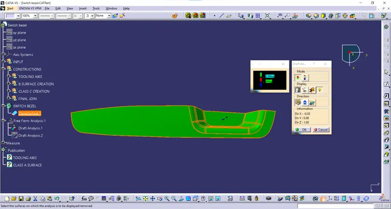
CONCLUSION: The component is cleared with a draft of 3 deg and hence it is manufacturable.