Week 8 - Challenge 1 - Draft Analysis on a Fan Cover
Objective : To perform a draft Analysis on the given CLASS A Surface Of a FAn Cover in CATIA V5.
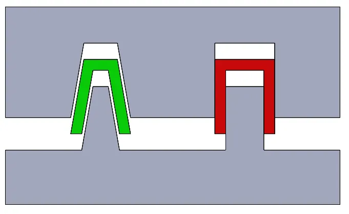
DRAFT: A Draft is an angle provided on the features of the product such as ribs, walls etc for ease of the removal in the molding operation.
- It should be provided on both inner and outer faces of the component.
- 3 deg is the nominal draft value given for most of the components.
- A 7 deg draft is used for the textured faces.
- 0.5 deg draft is also possible to manufacture.
Procedure:
- First check the connectivity of the given CLASS A Surface by using the Join or the Boundary command to ensure there is no gap in between.
- Analyze the best possible tooling axis for the given component.
- Proceed with the TOOLING AXIS with the New Axis System.
Step 1: First check the connectivity of the given CLASS A Surface by using the Join or the Boundary command to ensure there is no gap in between.
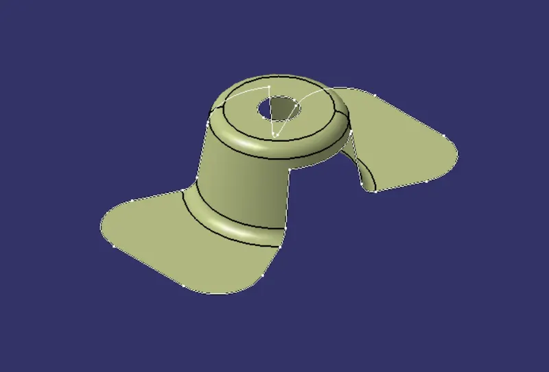
Step 2: Analyze the best possible tooling axis for the given component in the X/Y/Z by creating a Dummy Tooling axis for reference.
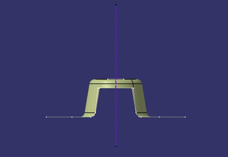
Step 3: Proceed with the TOOLING AXIS.
Create a Tooling Axis Clearing in X direction by intersecting the given CLASS A in XZ plane
After intersecting the surface in the XZ plane, create the reference line on the surface which might cause problems during the Ejection.
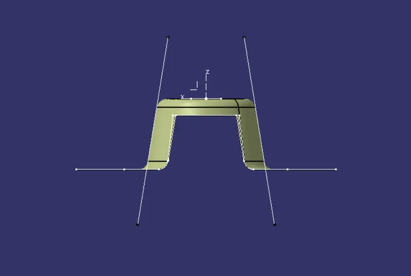
Bisecting Line: The bisecting line is the line splitting in two equal parts the angle between these two lines.
Create a bisecting line with the two reference lines created to get the Tooling Axis X DIrection.
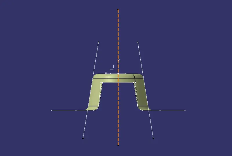
Follow the similar approach to get the Tooling Axis in Y Direction.
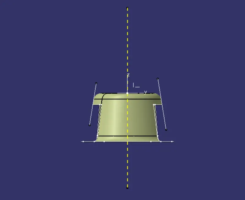
Now we create our Main Tooling Axis By Bisecting the tooling axis in X and Y Directions.
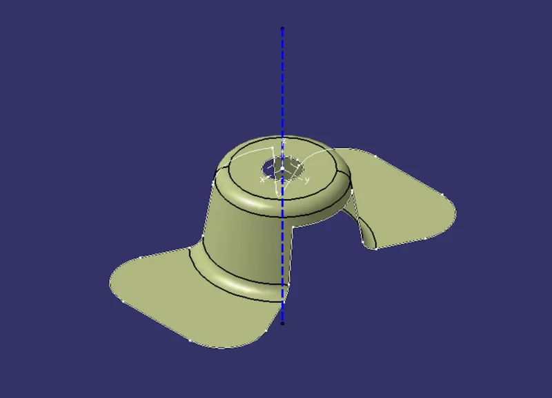
Step 4: Publish the main Tooling axis and the CLASS A Surface.
Step 5: Draft Analysis
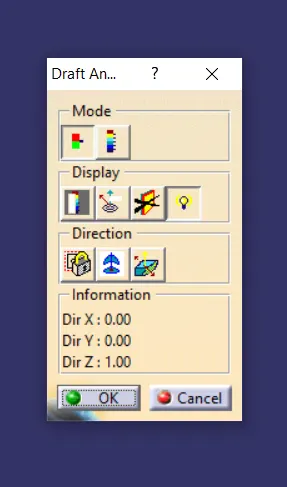
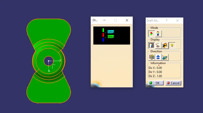
- Select the Material Mode in the Toolbar for Draft Analysis
- Add the Compass to the main Tooling axis and lock the tooling position.
- Click on the Surface for the output of the analysis.
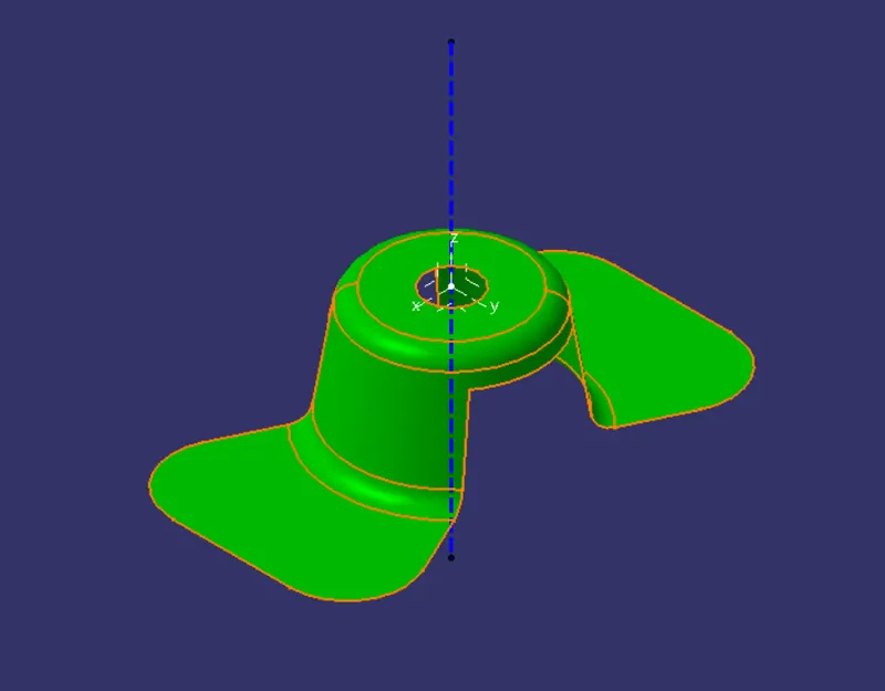
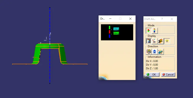
Results : The surface in green indicates that the component is cleared for Manufacturing with a draft of 3 Deg with Main Tooling Axis in Z Direction.
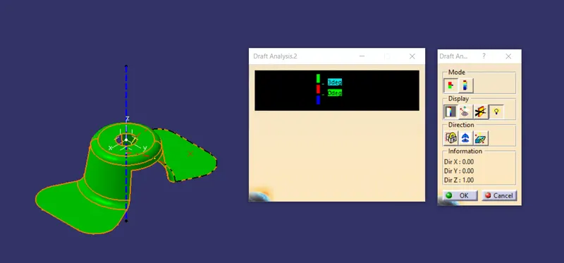
ISOMETRIC VIEW
FRONT VIEW
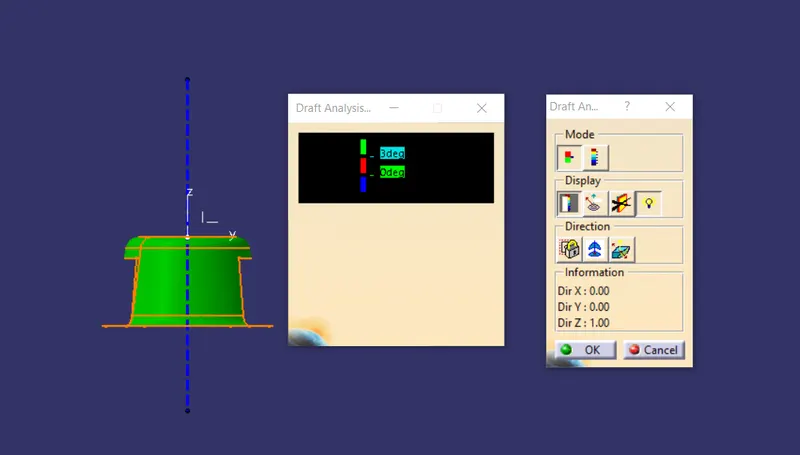
TOP VIEW
SIDE VIEW