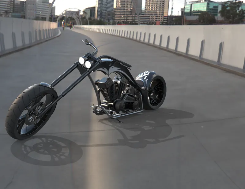
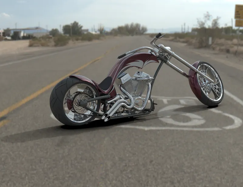
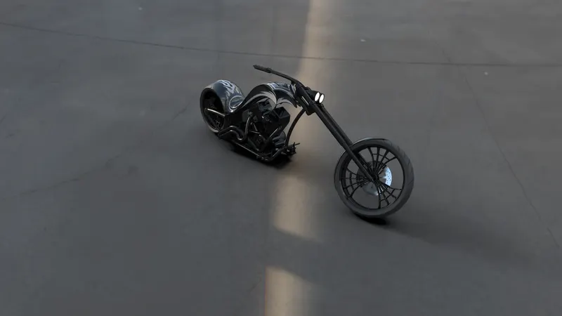
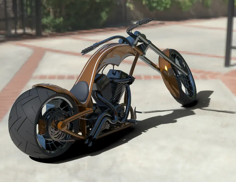
Photo Realistic Rendering
A PROJECT REPORT
MODELING OF AN AMERICAN CHOPPER IN SOLIDWORKS
INTRODUCTION
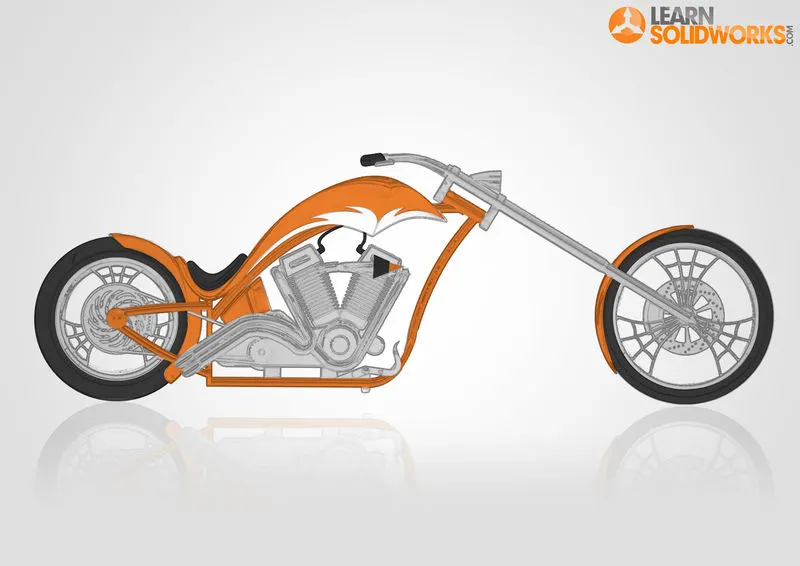
In this project we are going to learn about the Design Methodology of the American Chopper bike and assembling the modeled parts in software SOLIDWORKS. We get started with blueprint setup, which is followed by the Modeling of the individual components of the Chopper and assembling it. After getting done with Assembly, the next step is to apply some appearances and decals to give a Photorealism to the Chopper which is done in the Photoview 360 and Solidworks Visualize.
OBJECTIVE
- Understand And Implementing the Design Methodology used for Making An American Chopper Bike
- To get Hands On working with Solidworks Software
- To get familiarize with the Photoview 360 Solidworks Visualize For applying some Photorealism the Products
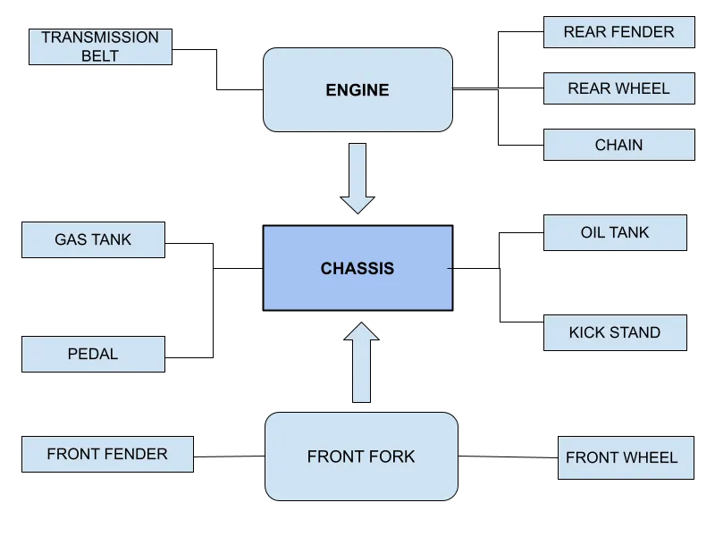
COMPONENTS OF AMERICAN CHOPPER
- Transmission belt
- Kickstand
- Front and rear fender
- Oil tank
- Foot pedal
- Chain
- Front Fork
- Engine with exhaust system
- Chassis
- Front wheel and rear wheel with rims and sprocket calipers
- Gas Tank
DESIGN APPROACH
FEATURES OR COMMANDS USED
- 2D Sketch
- Sketch Pictures
- Boss Extrude
- Revolve
- Extrude Cut
- Patterns
- Shell
- Mirror
- Filet and Chamfer
- Reference Geometry
- Projected Curve
- Composite Curve
- Surface Loft
- Surface Extrude
- Knit
- Mate
2D SKETCH :When you open a new part document, first you create a sketch. The sketch is the basis for a 3D model. You can create a sketch on any of the default planes (Front Plane, Top Plane, and Right Plane), or a created plane.
You can start by selecting:
- Sketch entity tools (line, circle, and so on)
- Sketch tool
- Planes
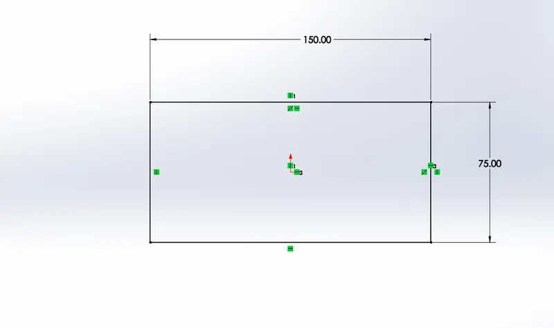
SKETCH PICTURES: Use pictures as an underlay for creating 2D sketches.Convert raster data to vector data using Autotrace. A sketch picture is inserted with its (0, 0) coordinate at the sketch origin.
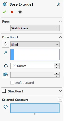
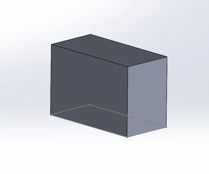
BOSS EXTRUDE: The Boss-Extrude/Base feature will project a 3D model with the selected sketch or face. Selecting a Plane. Using the 2D sketch or plane to create a 3D model, the Boss-Extrude feature button will prompt you to set parameters in the menu shown below.
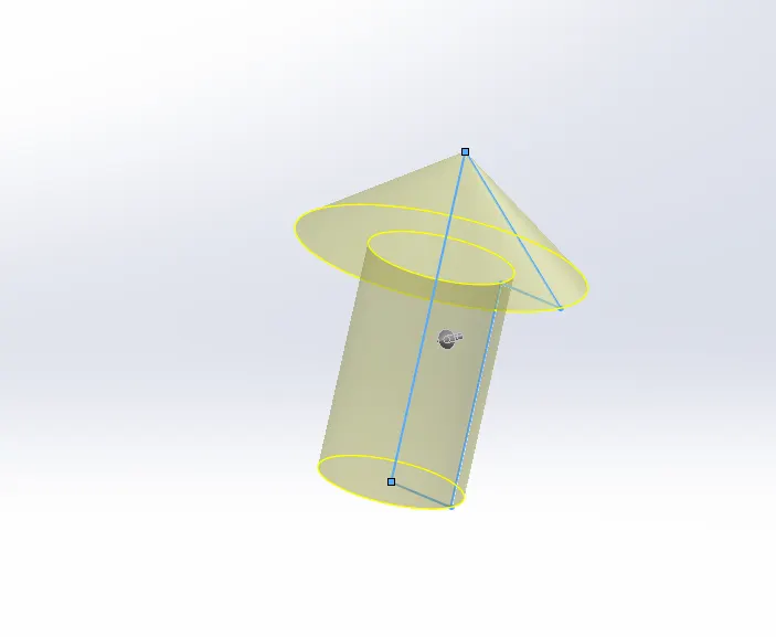
REVOLVE:Revolves add or remove material by revolving one or more profiles around a centerline. You can create revolved boss/bases, revolved cuts, or revolved surfaces. The revolve feature can be a solid, a thin feature, or a surface.
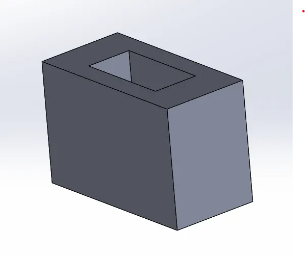
EXTRUDE CUT:Extruded cut feature removes material from the part. The End Condition, Draft, and Thin Feature options are the same as described in Extruded Boss/Base.
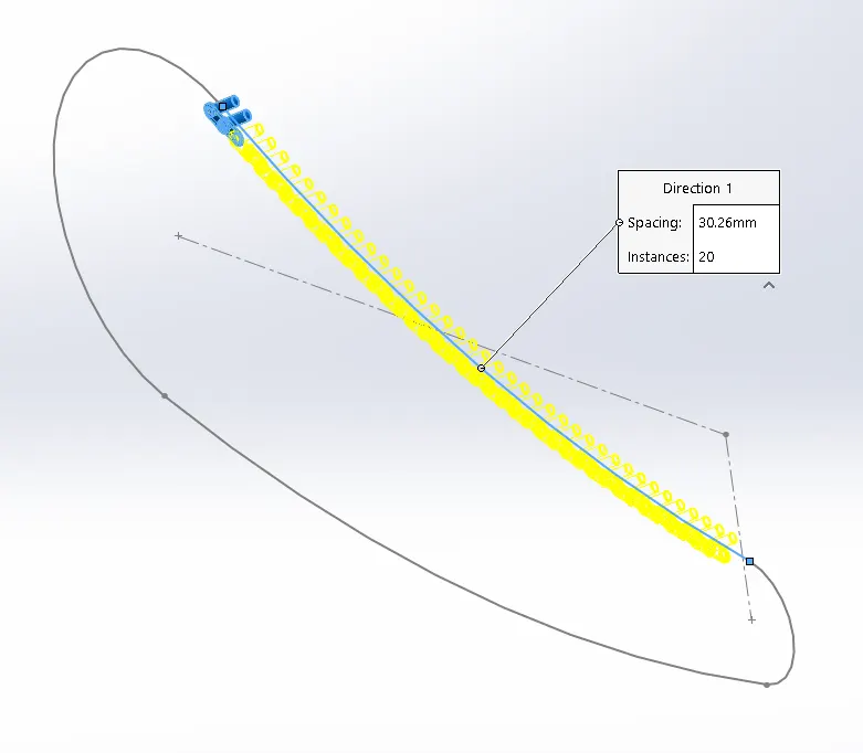
PATTERNS: The Curve Driven Pattern tool allows you to create patterns along a planar or 3D curve. To define the pattern, you can use any sketch segment, or the edge of a face (solid or surface), that lies along the plane. You can base your pattern on an open curve, or on a closed curve, such as a circle.
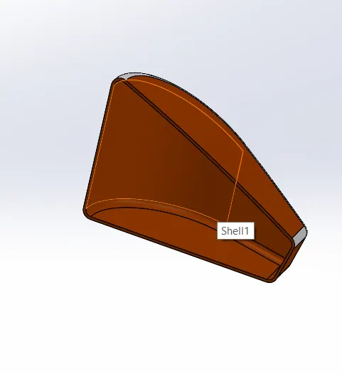
SHELL: The Shell Definition PropertyManager is used to define the thickness of thin and thick shell elements. You can also define a shell as a composite for static, frequency, and buckling studies.
MIRROR: Creates a copy of a feature, (or multiple features), mirrored about a face or a plane. You can select the feature or you can select the faces that comprise the feature.
FILET AND CHAMFER: A filet is a rounding of an interior or exterior corner of a part design.
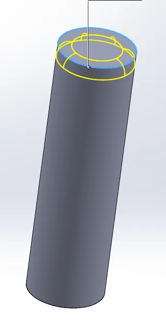
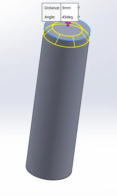
The chamfer tool creates a beveled feature on selected edges, faces, or a vertex. Set the Distance and Angle in the Chamfer PropertyManager or in the graphics area. A manipulator arrow appears that points in the direction in which the distance is measured.
REFERENCE GEOMETRY: Reference geometry includes items such as planes, axes, coordinate systems, and points. You can use reference geometry in the creation of several kinds of features. For example: Planes are used in lofts and sweeps.
PROJECTED CURVE: Project a sketched curve onto a model face to create a 3D curve. You can also create a 3D curve that represents the intersection of two extruded surfaces generated by creating sketches on two intersecting planes.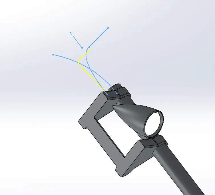
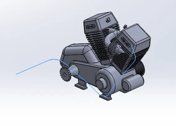
COMPOSITE CURVE: You can create composite curves by combining curves, sketch geometry, and model edges into a single curve.
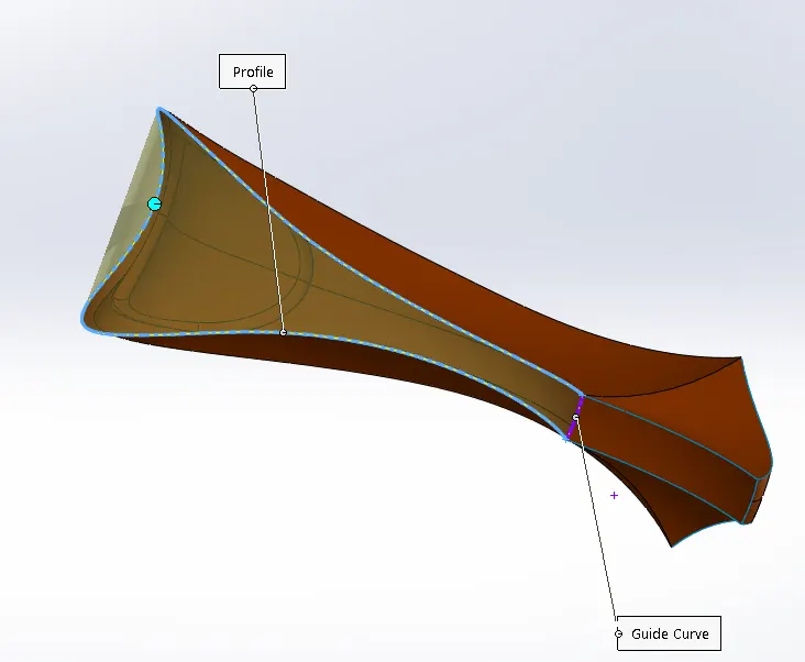
SURFACE LOFT: The loft feature is an important tool for (surface) modeling in SolidWorks. The loft feature creates a shape by making transitions between multiple profiles and guide curves. This tool is very valuable for modeling complex surfaces.
SURFACE EXTRUDE: Using the Surface Extrude feature, we can extrude the boundary edges of a face of a solid body or edges of a surface body in a customized direction.
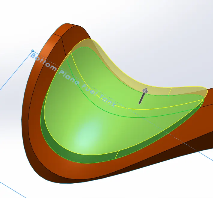
KNIT: Knit Surface tool is used to combine two or more faces and surfaces into one. Create a solid body when the knit surfaces form a closed volume, or leave as a surface body.Select Merge entities to merge faces with the same underlying geometry.
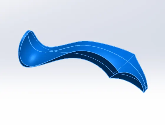
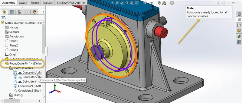
MATE: Mates create geometric relationships between assembly components. As you add mates, you define the allowable directions of linear or rotational motion of the components. You can move a component within its degrees of freedom, visualizing the assembly's behavior.
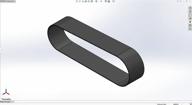
TRANSMISSION BELT
Belts are the cheapest utility for power transmission between shafts that may not be axially aligned. Power transmission is achieved by purposely designed belts and pulleys. The variety of power transmission needs that can be met by a belt-drive transmission system are numerous, and this has led to many variations on the theme. Belt drives run smoothly and with little noise, and provide shock absorption for motors, loads, and bearings when the force and power needed changes.
Features Used
- 2D Sketch
- Boss Extrude
- Fillet
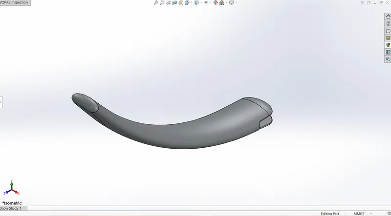
KICK STAND
A kickstand is a component on a bicycle or motorcycle that allows the bike to be kept upright without leaning against another object or the aid of a person. A kickstand is usually a piece of metal that flips down from the frame and makes contact with the ground. It is generally located in the middle of the bike or towards the rear.
Features Used
2D sketch
- Loft
- Cut Extrude
- Split
- Fillet
FENDER
Fenders are plastic or metal shields on bicycles that help riders tackle muddy or watery roads while riding. Its primary purpose is to prevent sand, mud, rocks, liquids, and other road spray from being thrown into the air by the rotating tire.
Features Used
- 2D Sketch
- Revolve
- Split
- Shell
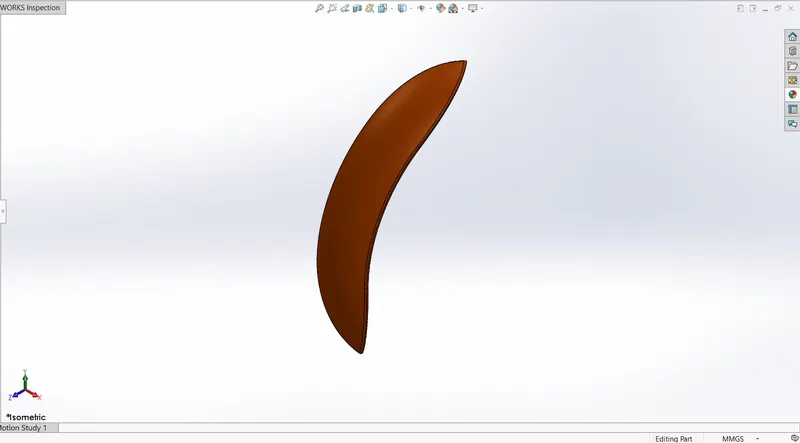
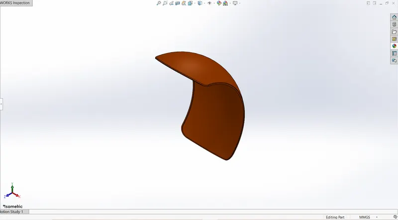
OIL TANK
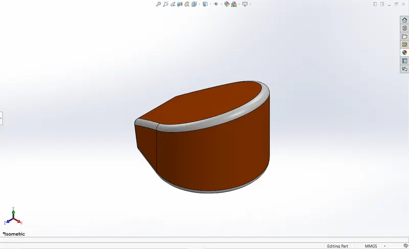
An oil tank is a component that is fitted into the crank/cam case ventilation system Installing an oil tank aims to reduce the amount of oil vapors re-circulated into the intake of the engine.
Features Used
- Boss Extrude
- Combine
- Shell
- Fillet
FOOT PEDAL
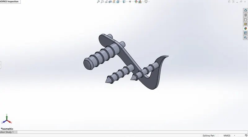
A pedal is a strong rigid body and used to rest the foot while riding a bike.
Features Used
- 2D Sketch
- Splines
- Boss Extrude
CHAIN
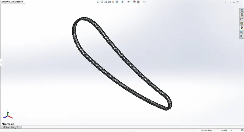
Chain drive is a way of transmitting mechanical power from one place to another. It is often used to convey power to the wheels of a vehicle, particularly bicycles and motorcycles. It is also used in a wide variety of machines besides vehicles.
Features Used
- 2D Sketch
- Sketch Blocks
- Circular Pattern
- Curve Driven Pattern
FRONT FORK
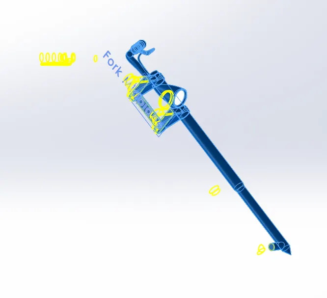
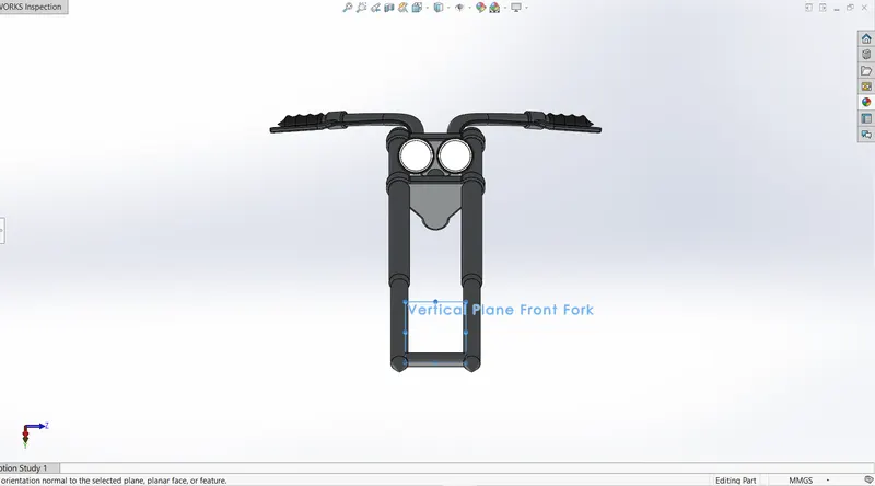
A motorcycle fork connects a motorcycle's front wheel and axle to its frame, typically via a yoke, also known as a triple clamp, which consists of an upper yoke joined to a lower yoke via a steering stem, a shaft that runs through the steering head, creating the steering axis. Most forks incorporate the front suspension and front brake, and allow the front wheel to rotate about the steering axis so that the bike may be steered. Most handlebars attach to the top clamp in various ways, while clip-on handlebars clamp to the fork tubes, either just above or just below the upper triple clamp.
Features Used
- 2D Sketch
- Revolve
- Cut Extrude
- Combine
- Projected Curve
- Dome
- Reference Geometries
ENGINE
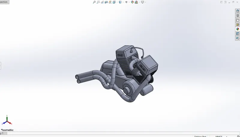
A motorcycle engine powers a motorcycle. Motorcycle engines are typically two-stroke or four-stroke internal combustion engines, Most engines have a gearbox with up to six or even 7 ratios. Reverse gear is occasionally found on heavy tourers, The rider changes gears on most motorcycles using a foot-pedal and manual clutch, but early models had hand-levers. More recently, some have automatic or semi-automatic gearboxes, and some using CVT transmission.
Features Used
- 2D Sketch
- Extrude
- Revolve
- Sweep
- Projected Curve
- Composite Curve
- Reference Geometries
CHASSIS
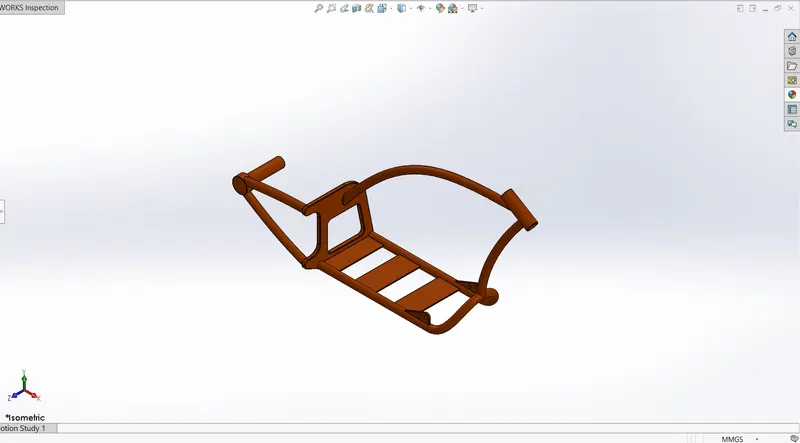
A motorcycle frame/chassis is a motorcycle's core structure. It supports the engine, provides a location for the steering and rear suspension, and supports the rider and any passenger or luggage. Also attached to the frame are the fuel tank and battery. At the front of the frame is found the steering head tube that holds the pivoting front fork, while at the rear there is a pivot point for the swingarm suspension motion. Some motorcycles include the engine as a load-bearing stressed member; while some other bikes do not use a single frame, but instead have a front and a rear subframe attached to the engine.
Features Used
- 2D Sketch
- Extrude
- Revolve
- Sweep
- Projected Curve
- Composite Curve
- Reference Geometries
- Split
- Combine
FRONT WHEEL
Motorcycle wheels are made to cope with radial and axial forces. They also provide a way of mounting other critical components such as the brakes, final drive and suspension. Spoked wheels are usually made using steel spokes with steel or aluminium rims. Cast wheels are predominantly made from an aluminium-alloy, but can also be made from more-exotic materials, such as magnesium content alloy or carbon fibe
Features Used
- 2D Sketch
- Extrude
- Revolve
- Sweep
- Reference Geometries
- Split
- Combine
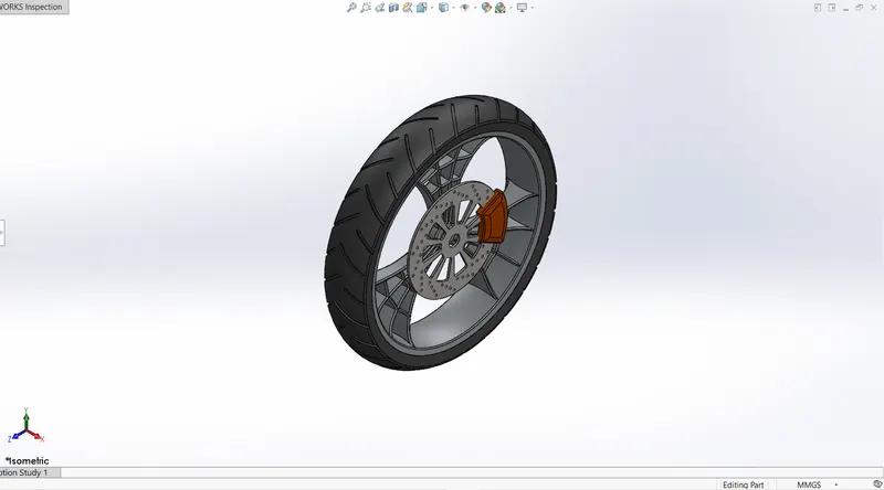
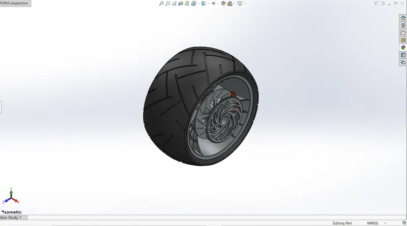
REAR WHEELS
The rear wheel is primarily used for accelerating the vehicle and moving it forward. It is wider than the front wheel. It gives stability to the vehicle.Rear-wheel drive (RWD) is a form of engine and transmission layout used in motor vehicles, where the engine drives the rear wheels only.
Features Used
- 2D Sketch
- Extrude
- Revolve
- Sweep
- Reference Geometries
- Split
- Combine
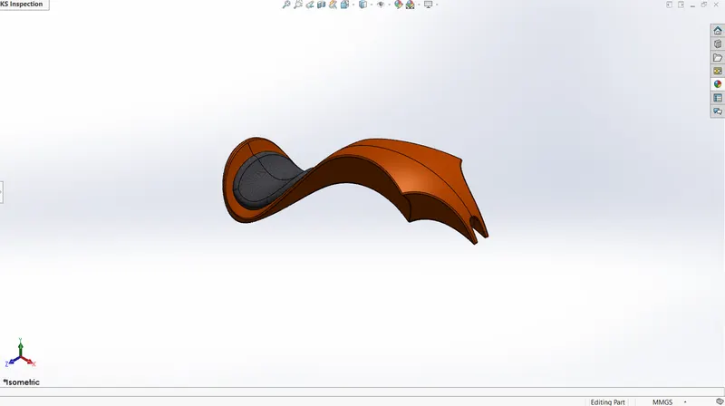
GAS TANK
Fuel tank (also called a petrol tank or gas tank) is a safe container for flammable fluids. Though any storage tank for fuel may be so called, the term is typically applied to part of an engine system in which the fuel is stored and propelled (fuel pump) or released (pressurized gas) into an engine.
Features Used
- 2D Sketch
- Boundary Surface
- Mirror
- Surface Extrude
- Knit
- Cut Sweep
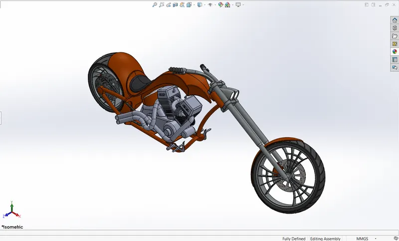
ASSEMBLY OF THE CHOPPER
All the parts were modeled and assembled together. In assembly, the mate feature is used to locate and relate the parts with one another. Chassis is the main component which is inserted first and then fixed. The other components were inserted one by one and by using planes for reference and giving the mate feature to give required relation between them in order to satisfy the assembly conditions.
RENDERING
Rendering is the process of generating a photorealistic or non-photorealistic image from a 2D or 3D model by means of a computer program. The resulting image is referred to as the render. Multiple models can be defined in a scene file containing. The scene file contains geometry, viewpoint, texture, lighting, cameras and shading information describing the virtual scene. The data contained in the scene file is then passed to a rendering program to be processed and output to a digital image or raster graphics image file. The term "rendering" is analogous to the concept of an artist's impression of a scene.
PHOTOVIEW 360 OVERVIEW
PhotoView 360 is a SOLIDWORKS add-in that produces photo-realistic renderings of SOLIDWORKS models. The rendered image incorporates the appearances, lighting, scene, and decals included with the model. PhotoView 360 is available with SOLIDWORKS Professional or SOLIDWORKS Premium.
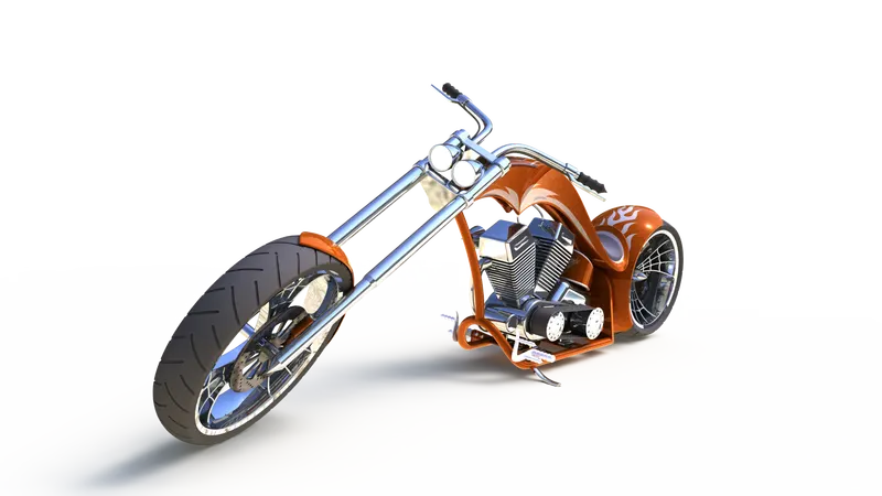
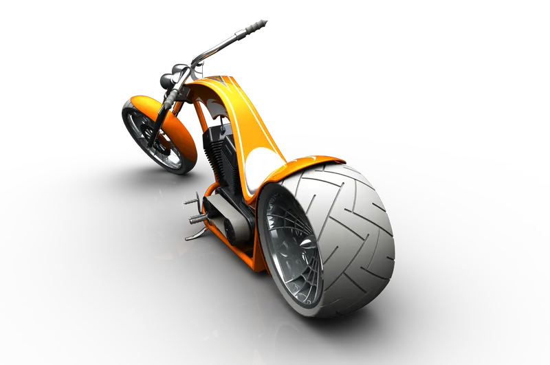
SOLIDWORKS VISUALIZE
Solidworsks Visualize allows you to leverage your 3D CAD data to create photo-quality content in the fastest and easiest way you can–from images to animations, interactive web content, and immersive Virtual Reality. Bring your products to life. SOLIDWORKS Visualize is the “camera” for your CAD data.