Radar Mast & Final Assembly of Yacht
A PROJECT REPORT ON
MODELING OF SUNSEEKER PREDATOR YACHT
INTRODUCTION
In this project we are going to learn about the conceptual modeling of the Sunseeker Predator Yacht, followed by the assembling of the modeled parts in SOLIDWORKS.The intent of the project is to have an in-depth idea about modeling procedure used for this kind of a sailing or cruising vessel.Cruising yachts may be designed for near-shore use or for passage-making. They may also be raced, but they are designed and built with the comfort and amenities necessary for overnight voyages. Qualities considered in cruising yachts include: performance, comfort under way, ease of handling, stability, living comfort, durability, ease of maintenance, affordability of ownership.
OBJECTIVE
- To get familiarized with the design approach to model this kind of power vessel.
- To design the exterior parts of a Sunseeker Predator Yacht.
- To Provide a Photorealistic view to the Modeled Yacht.
COMPONENTS OF THE YACHT
- Propeller
- Radar
- Hull
- Garage Door
- Front Seat
- Middle Seat
- Rear Seat
- Superstructure
- Radar Mast
DESIGN APPROACH
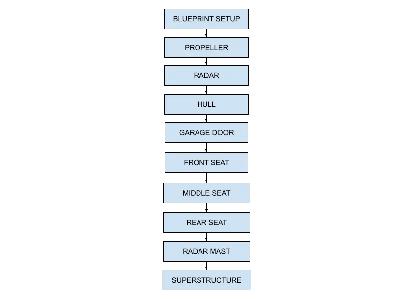
FEATURES OR COMMANDS USED
- 2D Sketch
- Boss Extrude
- Revolve
- Extrude Cut
- Patterns
- Shell
- Mirror
- Filet and Chamfer
- Reference Geometry
- Projected Curve
- Split Line
- Surface Loft
- Surface Extrude
- Knit
- Mate
- Filled Surface
- Ruled Surface
- Extend Surface
- Surface Trim
2D SKETCH :When you open a new part document, first you create a sketch. The sketch is the basis for a 3D model. You can create a sketch on any of the default planes (Front Plane, Top Plane, and Right Plane), or a created plane.
You can start by selecting:
- Sketch entity tools (line, circle, and so on)
- Sketch tool
- Planes
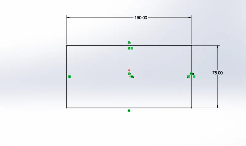
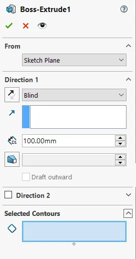
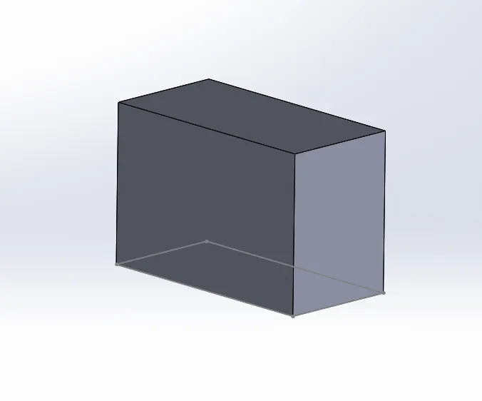
BOSS EXTRUDE: The Boss-Extrude/Base feature will project a 3D model with the selected sketch or face. Selecting a Plane. Using the 2D sketch or plane to create a 3D model, the Boss-Extrude feature button will prompt you to set parameters in the menu shown below.
REVOLVE:Revolves add or remove material by revolving one or more profiles around a centerline. You can create revolved boss/bases, revolved cuts, or revolved surfaces. The revolve feature can be a solid, a thin feature, or a surface.
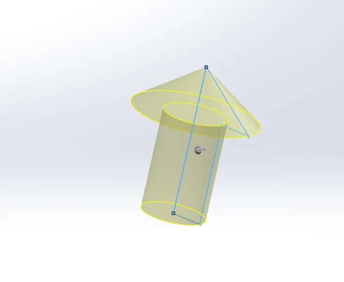
EXTRUDE CUT:Extruded cut feature removes material from the part. The End Condition, Draft, and Thin Feature options are the same as described in Extruded Boss/Base.
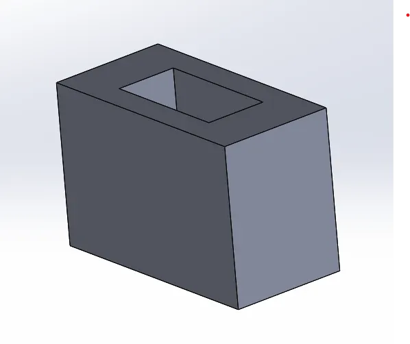
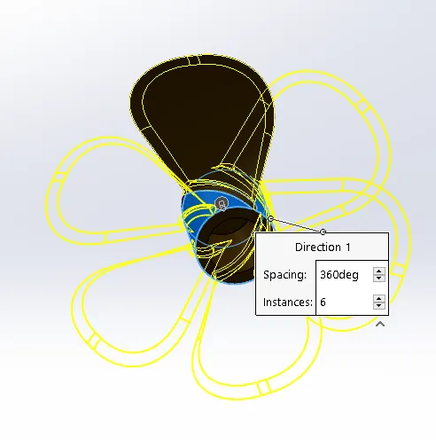
PATTERNS: The Curve Driven Pattern tool allows you to create patterns along a planar or 3D curve. To define the pattern, you can use any sketch segment, or the edge of a face (solid or surface), that lies along the plane. You can base your pattern on an open curve, or on a closed curve, such as a circle.
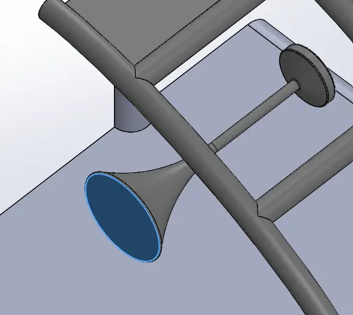
SHELL: The Shell Definition PropertyManager is used to define the thickness of thin and thick shell elements. You can also define a shell as a composite for static, frequency, and buckling studies.
MIRROR: Creates a copy of a feature, (or multiple features), mirrored about a face or a plane. You can select the feature or you can select the faces that comprise the feature.
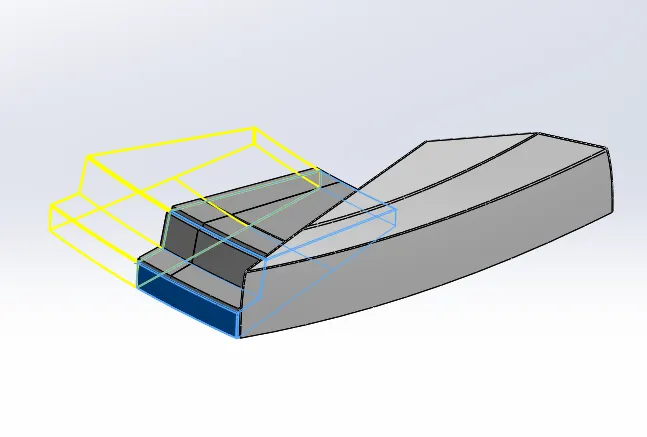
FILET AND CHAMFER: A filet is a rounding of an interior or exterior corner of a part design.
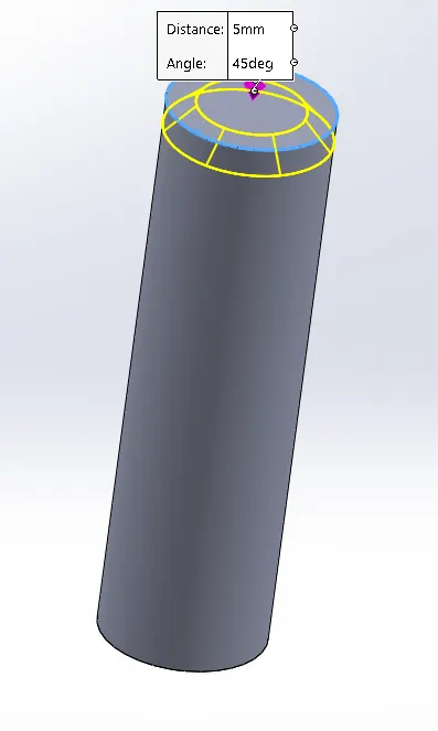
The chamfer tool creates a beveled feature on selected edges, faces, or a vertex. ... Set the Distance and Angle in the Chamfer PropertyManager or in the graphics area. A manipulator arrow appears that points in the direction in which the distance is measured.
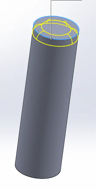
REFERENCE GEOMETRY: Reference geometry includes items such as planes, axes, coordinate systems, and points. You can use reference geometry in the creation of several kinds of features. For example: Planes are used in lofts and sweeps.
PROJECTED CURVE: Project a sketched curve onto a model face to create a 3D curve. You can also create a 3D curve that represents the intersection of two extruded surfaces generated by creating sketches on two intersecting planes.
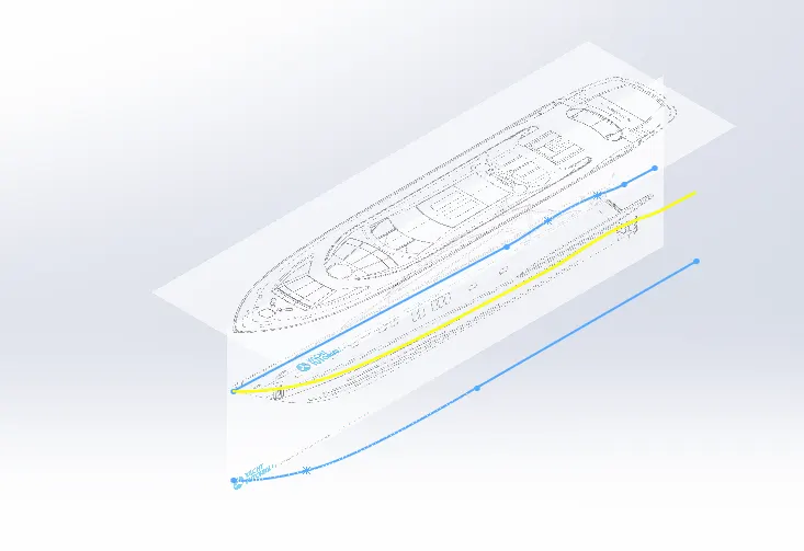
SURFACE LOFT: The loft feature is an important tool for (surface) modeling in SolidWorks. The loft feature creates a shape by making transitions between multiple profiles and guide curves. This tool is very valuable for modeling complex surfaces.
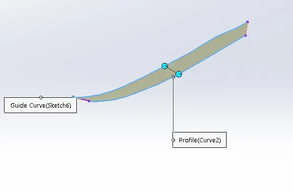
SURFACE EXTRUDE: Using the Surface Extrude feature, we can extrude the boundary edges of a face of a solid body or edges of a surface body in a customized direction.
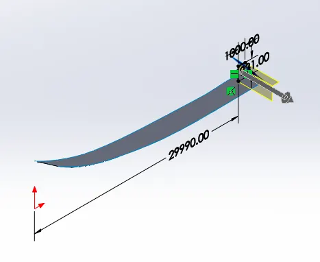
KNIT: Knit Surface tool is used to combine two or more faces and surfaces into one. Create a solid body when the knit surfaces form a closed volume, or leave as a surface body.Select Merge entities to merge faces with the same underlying geometry.
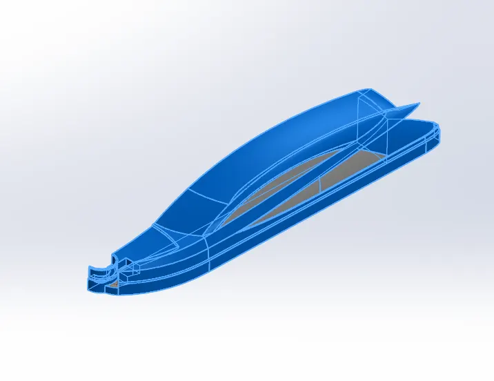
FILED SURFACE: The Filled Surface feature constructs a surface patch with any number of sides, within a boundary defined by existing model edges, sketches, or curves, including composite curves.
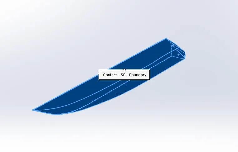
RULED SURFACE:The Ruled Surface command creates surfaces that extend out in a specified direction from selected edges.
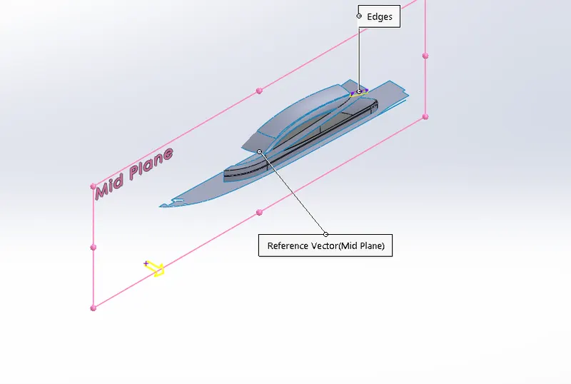
EXTEND SURFACE: Extends a surface by selecting an edge, multiple edges, or a face.
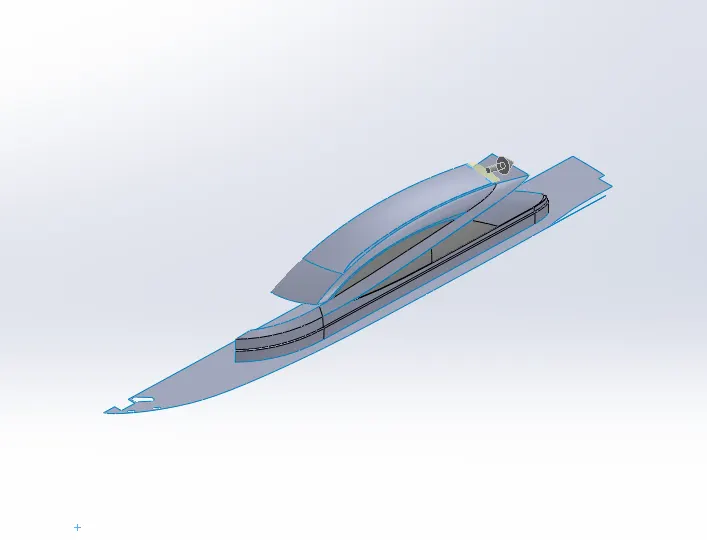
SURFACE TRIM: It uses a surface, plane, or sketch as a trim tool to trim intersecting surfaces. You can also use a surface in conjunction with additional surfaces, as mutual trim tools.
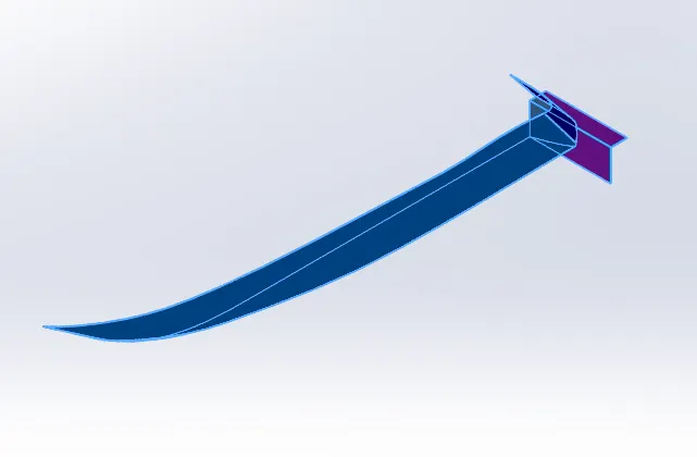
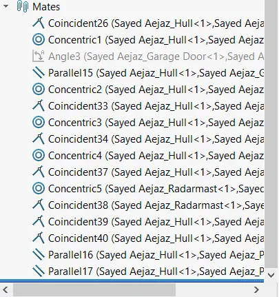
MATE: Mates create geometric relationships between assembly components. As you add mates, you define the allowable directions of linear or rotational motion of the components. You can move a component within its degrees of freedom, visualizing the assembly's behavior.
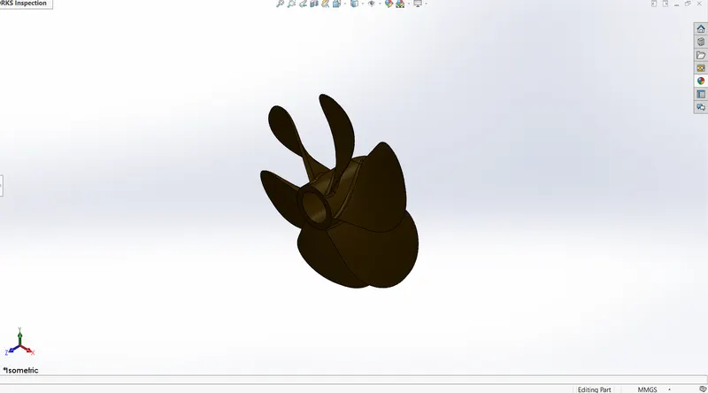
PROPELLER
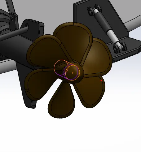
A propeller is a device with a rotating hub and radiating blades that are set at a pitch to form a helical spiral, that, when rotated, exerts linear thrust upon a working fluid, such as water or air Propellers are used to pump fluid through a pipe or duct, or to create thrust to propel a boat through water or an aircraft through air. The blades are specially shaped so that their rotational motion through the fluid causes a pressure difference between the two surfaces of the blade by Bernoulli's principle which exerts force on the fluid Most marine propellers are screw propellers with helical blades rotating on a propeller shaft with an approximately horizontal axis.
Features Used
- 2D Sketch
- Revolve
- Cut Extrude
- Circular Pattern
- Filet
RADAR
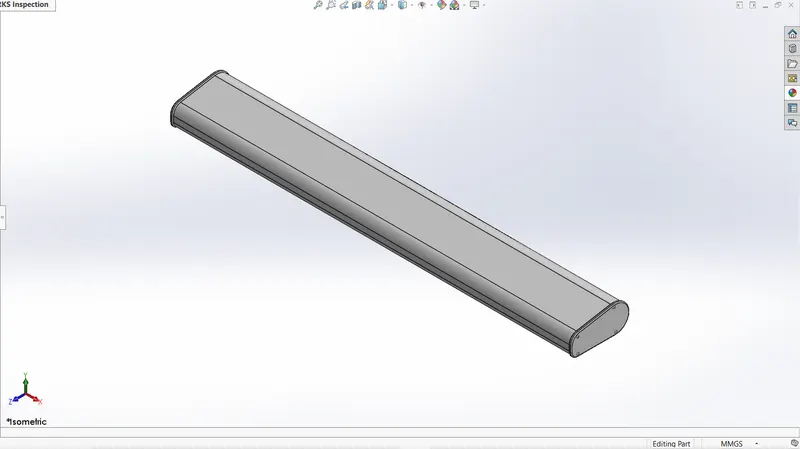
Radar is a vital navigation component for safety at sea and near the shore. Captains need to be able to maneuver their ships within feet in the worst of conditions and to be able to navigate "blind", when there is no visibility at night or due to bad weather. In addition to vessel-based marine radars, in port or in harbor, shore-based vessel traffic service radar systems are used by harbormasters and coast guard to monitor and regulate ship movements in busy waters.
Features Used
- 2D Sketch
- Boss Extrude
- Cut Extrude
- Sketch Patterns
- Split Line
- Filet
HULL
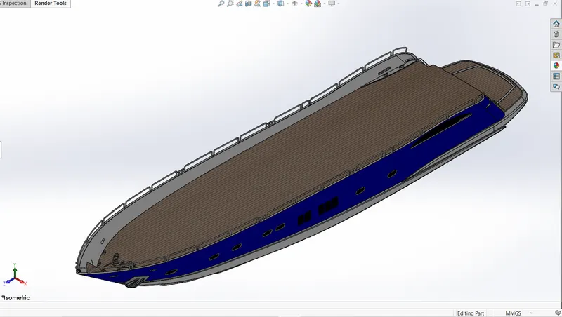
A hull is the watertight body of a ship, boat, or flying boat. The hull may open at the top (such as a dinghy), or it may be fully or partially covered with a deck. Atop the deck may be a deckhouse and other superstructures, such as a funnel, derrick, or mast. The line where the hull meets the water surface is called the waterline.
Features Used
- 2D Sketch
- Sketch Picture
- Boss Extrude
- Cut Extrude
- Projected Curves
- Surface LOft
- Surface Trims
- Surface Knits
- Reference Geometries
- Sweeps
- Dome
- Linear Pattern
- Mirror
- Filet
GARAGE DOOR
It is a door to the Yacht door space that opens either manually or by an electric motor. Garage doors are frequently large enough to accommodate automobiles and other vehicles.
Features Used
- 2D Sketch
- Cut Extrude
- Mirror
- Filet
FRONT SEAT
Features Used
- 2D Sketch
- Sketch Picture
- Surface Sweep
- Surface Loft
- Surface Trim
- Surface Fill
- Filet
- Revolve
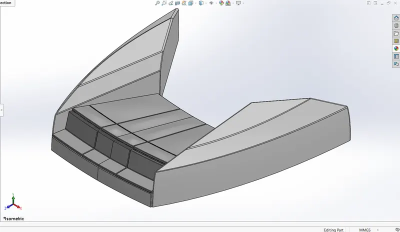
MIDDLE SEAT
Features Used
- 2D Sketch
- Sketch Picture
- Boss Extrude
- Cut Extrude
- Filet
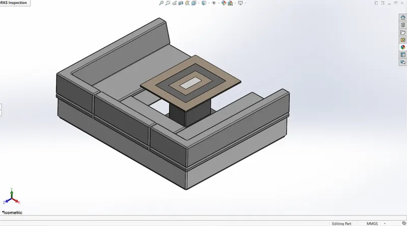
REAR SEAT
Features Used
- 2D Sketch
- Sketch Picture
- Surface Sweep
- Surface Loft
- Ruled Surface
- Surface Offset
- Surface Knit
- Filet
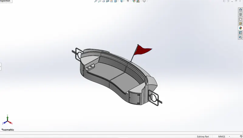
SUPERSTRUCTURE
A superstructure is an extended construction of any building or platform that rises above the rest of the building or platform in a distinct manner. The word comes from a combination of two Latin words, the Latin prefix ‘super’ means in addition or above or in excess of, whereas the stem word ‘structure’ means to build or to heap up. Thus, superstructure means to add a construction to an already existing structure. In ships this is the name given to the part of the ship that emerges from the deck. However any mast, sails, any armaments or arsenal are not included in this category.
Features Used
- 2D Sketch
- Sketch Picture
- Surface Sweep
- Surface Loft
- Ruled Surface
- Surface Knit
- Surface Extrude
- Projected Curve
- 3D Sketch
- Surface Trim
- Surface Extend
- Mirror
- Filet
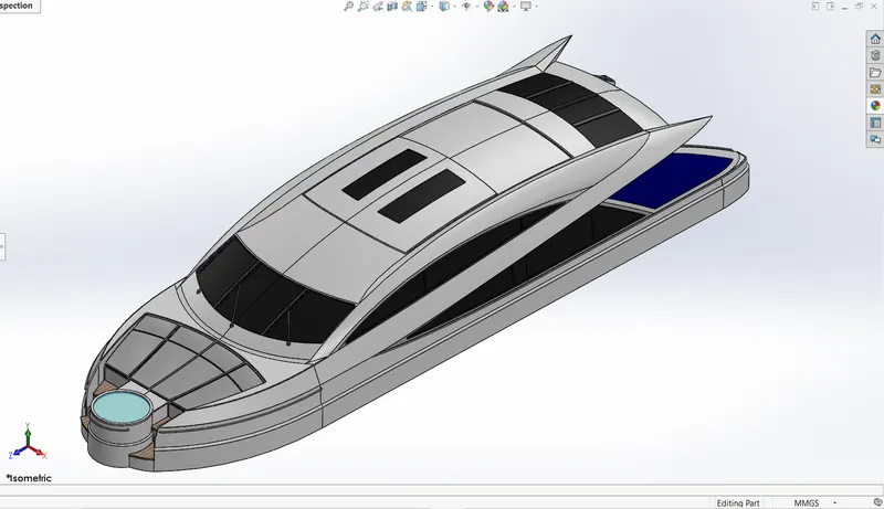
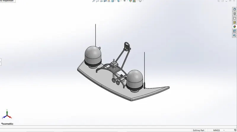
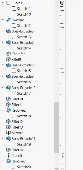
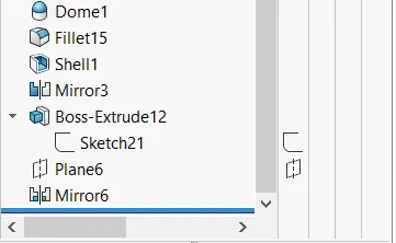
RADAR MAST
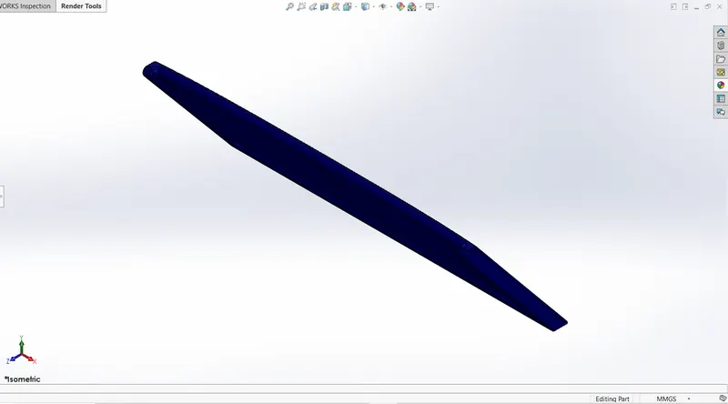
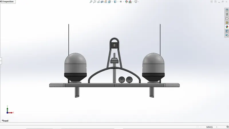
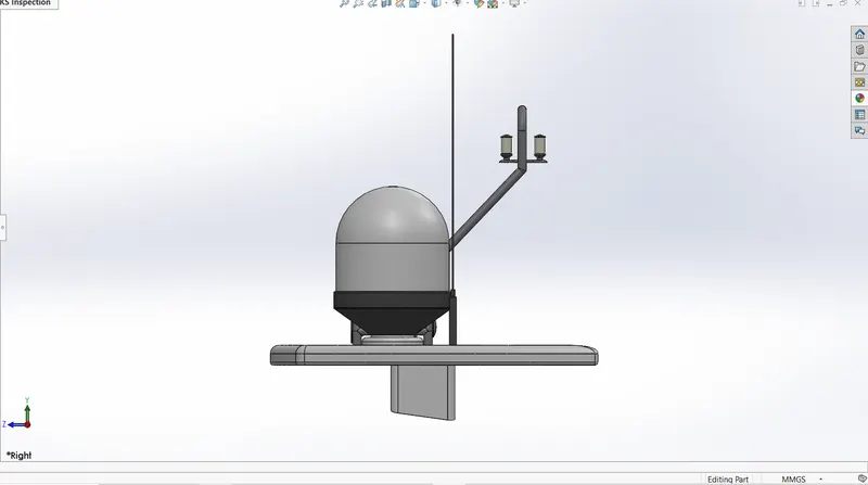
A radar mast supports the radar , antennas, and satellite dome. It also contains the important electronic devices that are connected with radar to roide signals received through the antennas and also includes horns and lights with it.
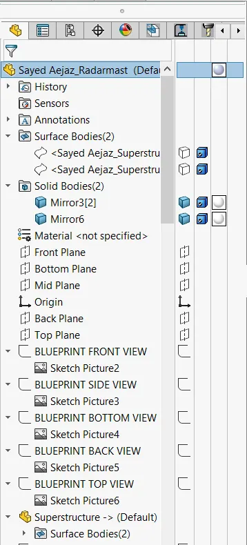
It was designed after importing the top surface of the superstructure as interface surface
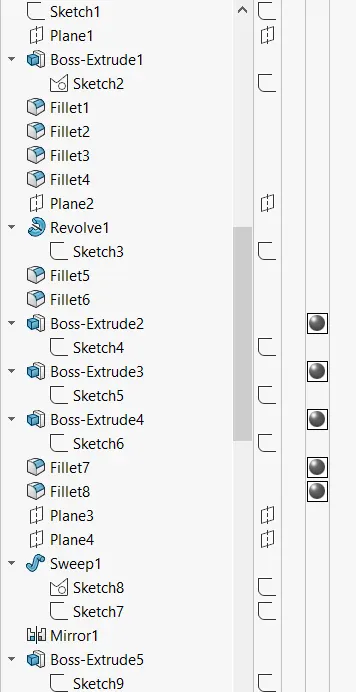
Features Used
- 2D Sketch
- Sketch Pictures
- Sweep
- Boss Extrude
- Shell
- Dome
- Mirror
ASSEMBLY OF THE YACHT
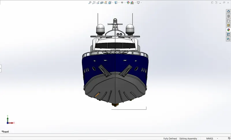
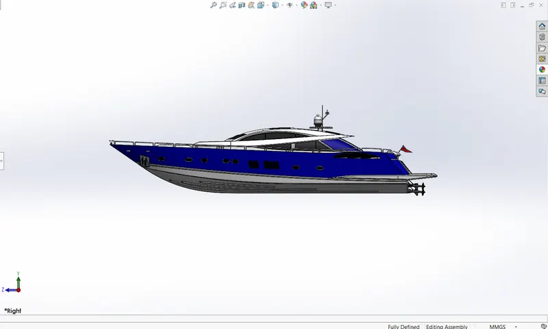
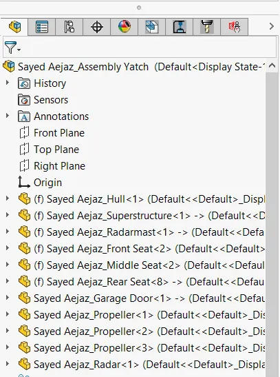
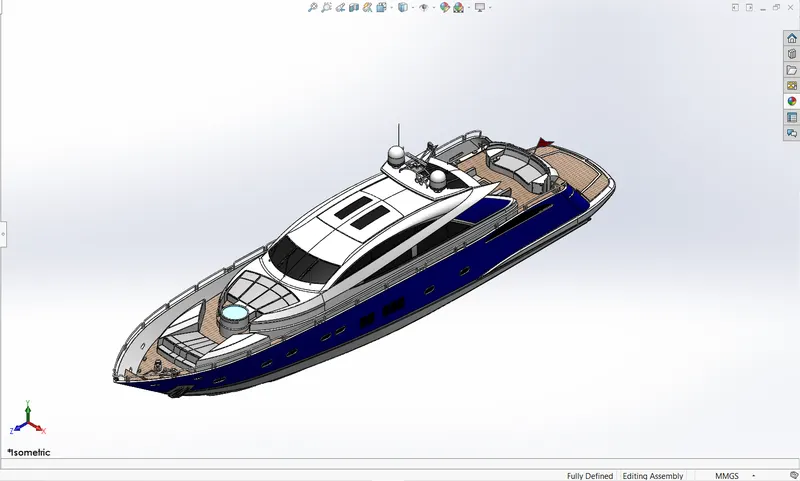
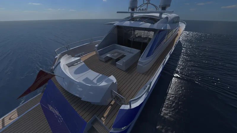
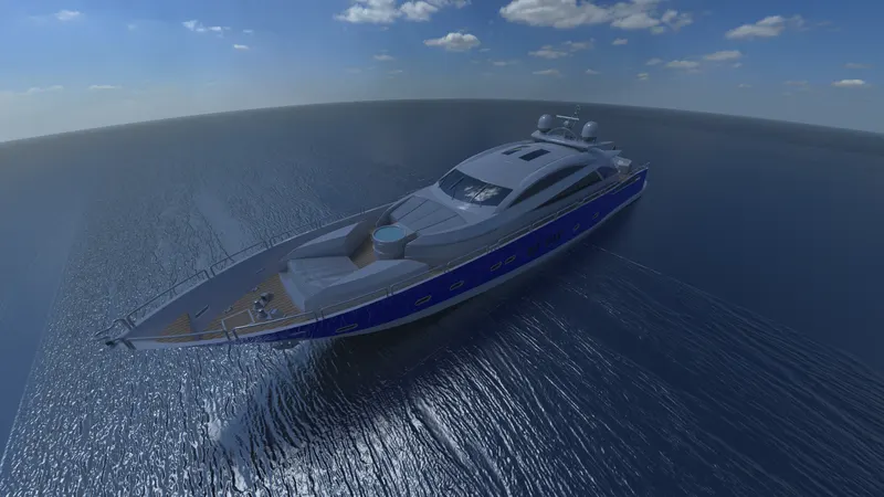
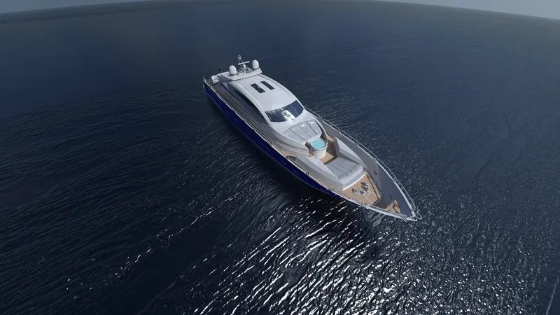
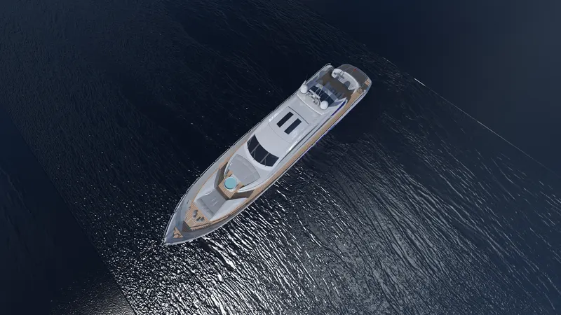
All the parts were modeled and assembled together. In assembly, the mate feature is used to locate and relate the parts with one another. Chassis is the main component which is inserted first and then fixed. The other components were inserted one by one and by using planes for reference and giving the mate feature to give required relation between them in order to satisfy the assembly conditions.
RENDERING
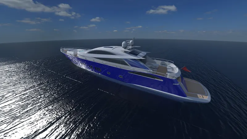
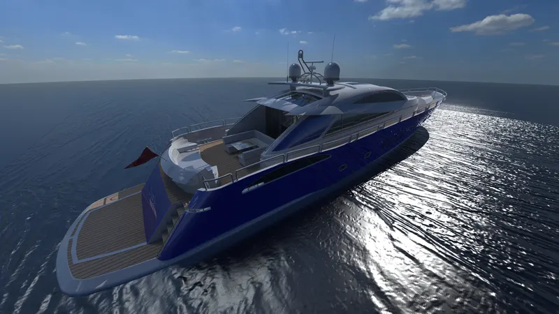
Rendering is the process of generating a photorealistic or non-photorealistic image from a 2D or 3D model by means of a computer program. The resulting image is referred to as the render. Multiple models can be defined in a scene file containing. The scene file contains geometry, viewpoint, texture, lighting, cameras and shading information describing the virtual scene. The data contained in the scene file is then passed to a rendering program to be processed and output to a digital image or raster graphics image file. The term "rendering" is analogous to the concept of an artist's impression of a scene.
SOLIDWORKS VISUALIZE
Solidworsks Visualize allows you to leverage your 3D CAD data to create photo-quality content in the fastest and easiest way you can–from images to animations, interactive web content, and immersive Virtual Reality. Bring your products to life. SOLIDWORKS Visualize is the “camera” for your CAD data.
RADAR MAST
ASSEMBLY OF YACHT