Week 9 - Project - Master Section Development
WEEK-9
MASTER SECTION DEVELOPMENT
AIM
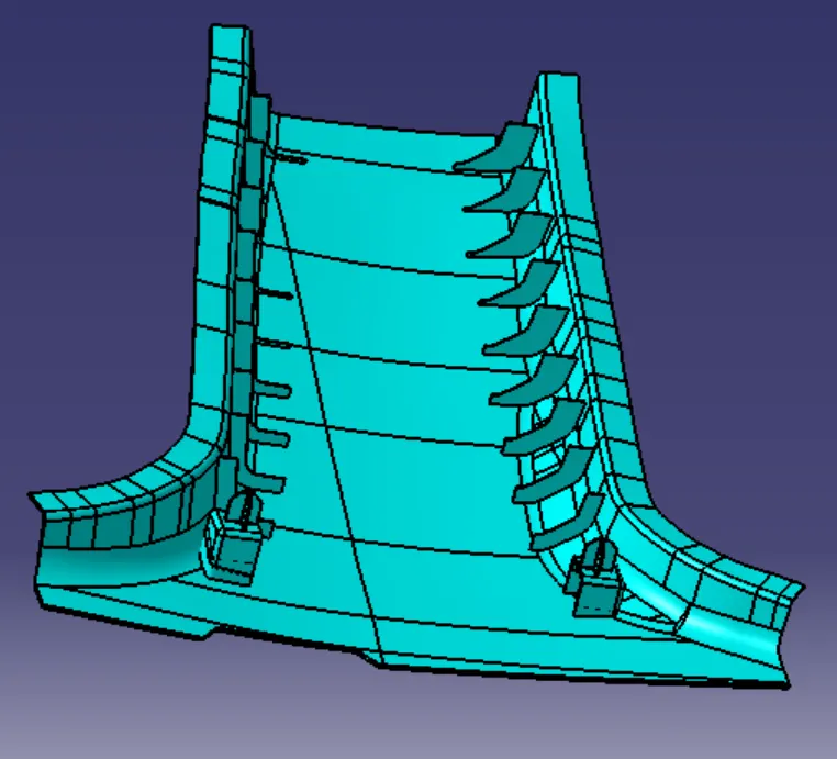
To create the fully developed model of the B-pillar of a car by incorporating B-side features like dog house and ribs at appropriate locations following the given master section.
THEORY
B-PILLAR:
Pillars provide most of the support to the roof structure. These pillars are named alphabetically from starting from the front of the vehicle. B-pillar sits between the front and rear door. Apart from strengthening the car's structure, it provides the clamping necessary for the front door to close and hinge support for the rear door. It is one of the complex parts to design in an automotive body. It is welded to the roof at the top and the vehicle's floor pan at the bottom.
DESIGN LIFE CYCLE
There are four essential stages in a design life cycle:
1. CONCEPT SKETCHING
Concept sketches are a rough idea of the shape of the product. These are not final sketches but innovative and imaginative sketches.
2. CLASS-A STYLING SURFACE
The obtained concept sketches are fed into the computer either in 2D or isometric view to generate the styling surface. This is the stage where the 3D modeling of CAD surfaces begins.
3. CLAY MODELING
Automotive clay sculpting help translates a designer's vision into a tangible reality. This is a way to pre-visualize concepts, which helps decision-making before taking the products further for manufacturing. The class-A surfaces are validated through clay modeling. The clay model is produced using clay and CNC tools. The role of this stage is to create the model according to the concept sketch and scan it using photometry to create the 3D CAD model.
4. NPD CAD
In this stage, the class-A surface is taken, and the product is designed with all the design rules, design for assembly and thickness, and all other necessary constraints. The model out of NPD CAD directly goes for manufacturing.
PROCEDURE
1. Inspecting the class-A surfaces
The first step every design engineer must follow is checking the given class-A surfaces. This is done in CATIA using the boundary option and visually inspecting the output. Any discontinuities or patches must be fixed up in the initial stage of the design to avoid errors in the later stage of the design.
2. Defining the tooling axis
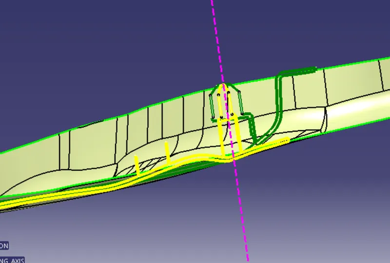
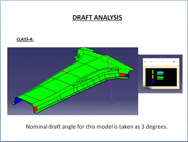
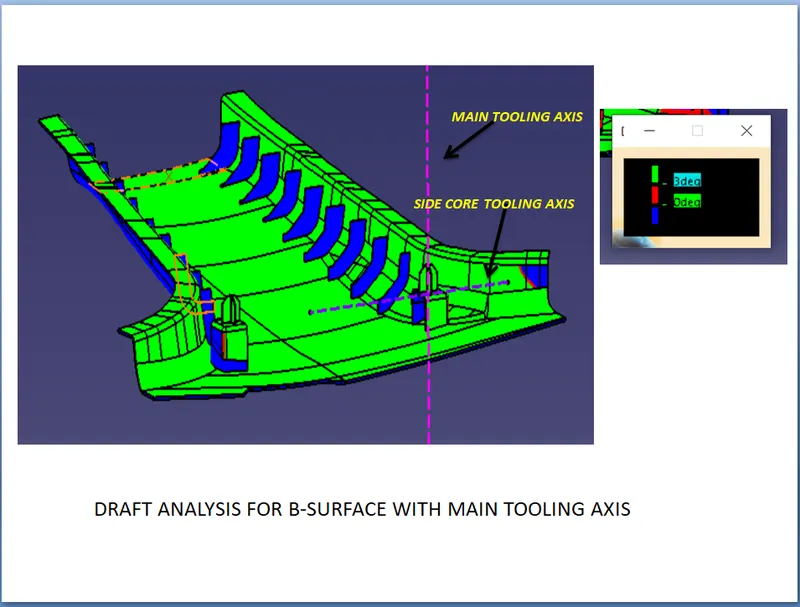
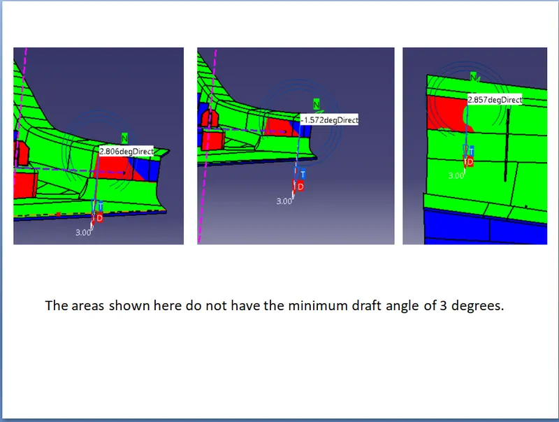
Defining or knowing the tooling direction is very important because it improves the quality of the design by decreasing the lead time. The given class-A and the master section are analyzed to derive the tooling direction for the given surface. In this case, the tooling direction for the edges of the locators in the master section is taken as the tooling direction for the given model. Draft analysis is performed on class-A to confirm the draft angles for all the surfaces with the tooling direction.
3. Creating the B and C surfaces
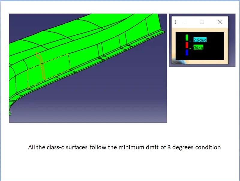
The class-A surface is offset by 2.5mm (given thickness for the component) inward directions to get the corresponding B-surface, and the flanges for A-surface are created using the sweep command. These flanges are offset by the same distance in the same direction, and the offset surfaces are fixed. The B-surfaces and the flanges are extrapolated until they touch each other and trim the required portion. Using the sweep command and the boundary of the class-A as input, the C-surface is created at an angle of 3 degrees with the tooling axis. All the A, B, C surfaces are joined and trimmed together, and the surface body is converted into the solid model using the closed surface command.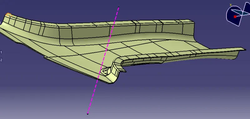
4. Creation of Dog house and Locators
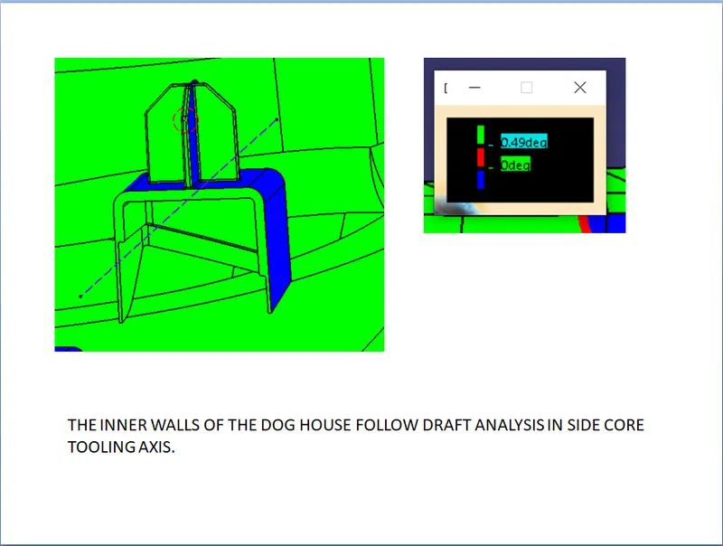
From the master section, the necessary boundaries are extracted using the sketch feature and extruded in the direction perpendicular to the sketch. The multiple surfaces are trimmed together to form the inner surfaces of the dog house, and the obtained output is thickened by 2mm to get the solid body. The required B-surfaces are extracted and offset by 4-6mm and are used to split the solid body to avoid sink marks. The outer surfaces of the dog house are extracted and are offset by 1.2mm (to get a c value of 0.8mm). The dog house is split using these surfaces as well. A side tooling axis is created in the X-direction, and the inner faces of the dog house are drafted with this side tooling axis about 0.5 degrees.
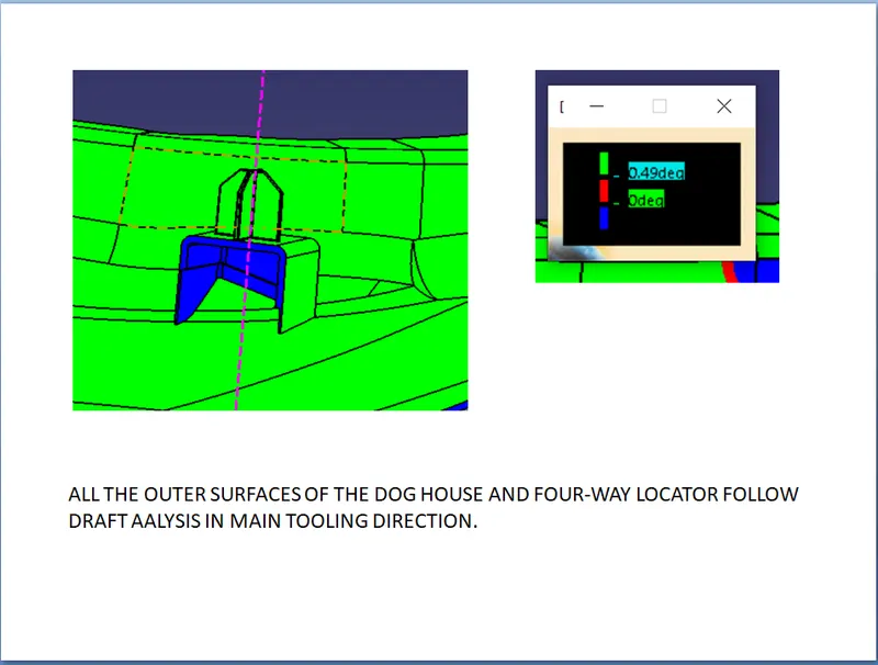
In the same way, the necessary boundaries of the 4-way locator are extracted and extruded. These extruded faces are now thickened and drafted with the main tooling axis. The 4-way locator is now union trimmed with dog house, and the critical areas are filleted by taking the reference values from the master section. The same dog house with a locator is obtained on the other side using the symmetry feature.
5. Creation of Ribs
A positioned sketch is created using the planes, and the sketch is extruded in the perpendicular direction to get the surface of the rib. The solid model is created by thickening the surface body. The B-surfaces are extracted and offset by 10mm (which is five times the nominal wall thickness), the solid body is split with the offset B-surface as the element, and the output is union trimmed with the B-pillar trim. The rib surfaces are drafted and filleted to complete the B-side features of the B-pillar trim.
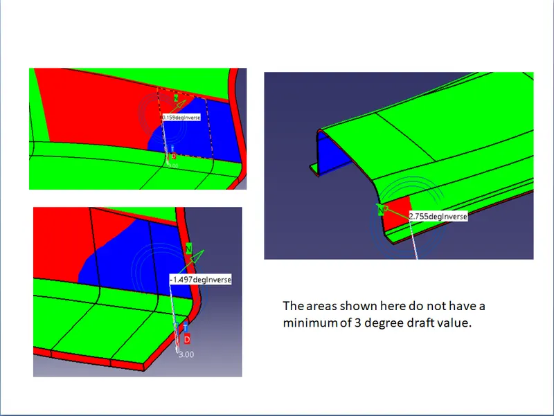
6. Performing draft analysis
FINAL MODEL
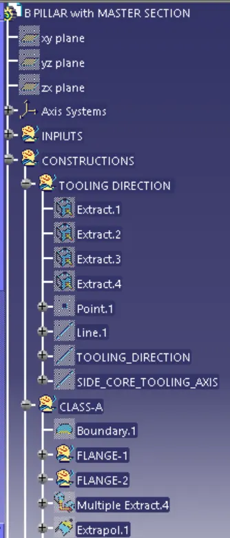
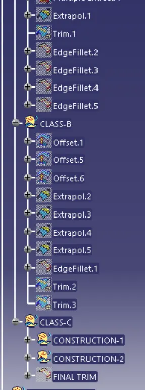
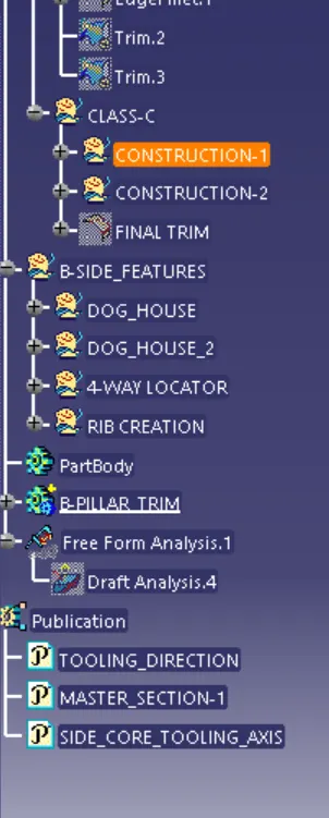
Geometric tree