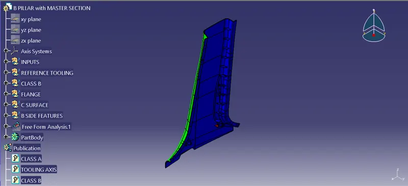
Week 9 - Project - Master Section Development
AIM: To develop the solid plastic component from the given master sections along with the engineering features and also perform the draft analysis.
REPORT:
- Examine the given inputs i.e. the master sections and the class A surface to develop the component
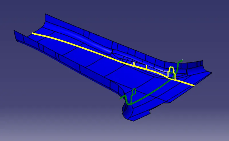
- To create the tooling axis extract the opposite faces from the two master sections provided
- Form a bisecting line using these faces and we would get the Tooling Axis
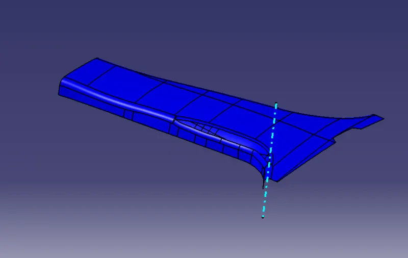
- The next step is to create the Class B Surface for that offset the class A surface by 2mm
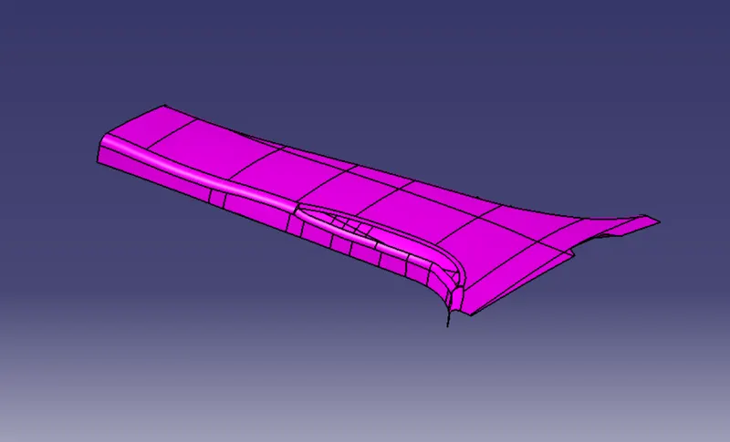
- Now we need to create the flanges following the master section
- Extract the edges to with the flanges are to be connected and sweep it
- Match the sweeped surface with the master section and we would get the Flanges
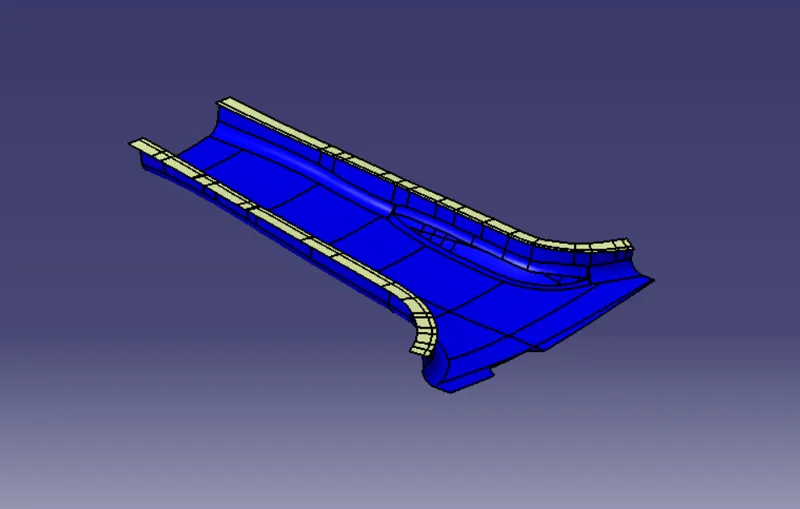
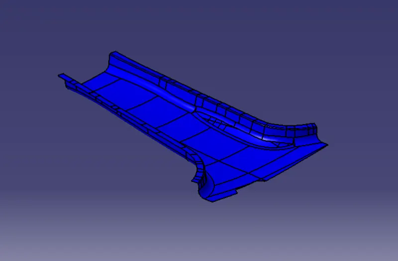
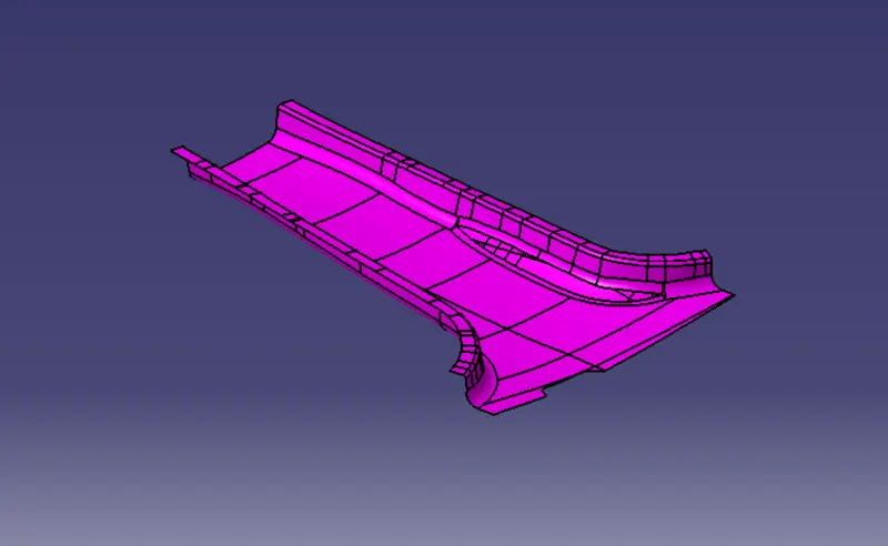
- Offset the flanges and trim it with respective class A & class B surfaces
- Class A with flange:
- Class B with flange:
- To obtain the Class C Surface create boundary for class A surface with flange and sweep it with 3° draft
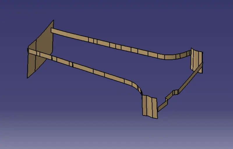
- Then trim the C surface with class A & B and join them to form the final component
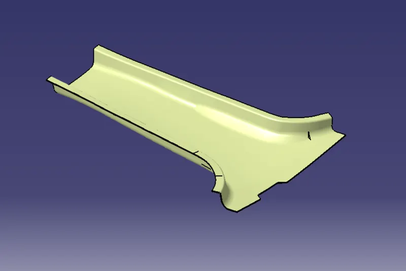
- Then use closesurface command to add thickness and form solid component
- The next step is to create the attachment features for this we need to follow the master sections
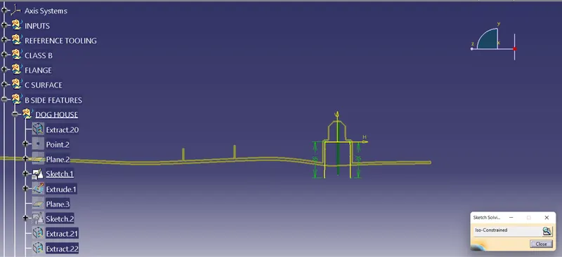
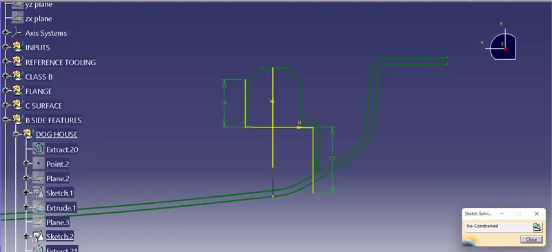
- To form the dog house refer the master sections and sketch the profile then extrude it
- Provide thickness to the walls and give 0.5° draft on faces
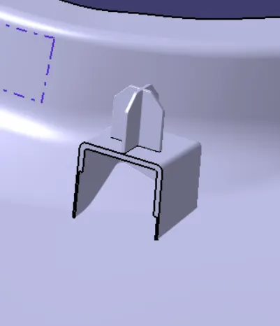
- Ensure that doghouse wall thickness at the intersection of the part wall ( C ) should be 40% or less than the main wall stock ( T ) also height of ( B ) should be between 3.0 – 6.0
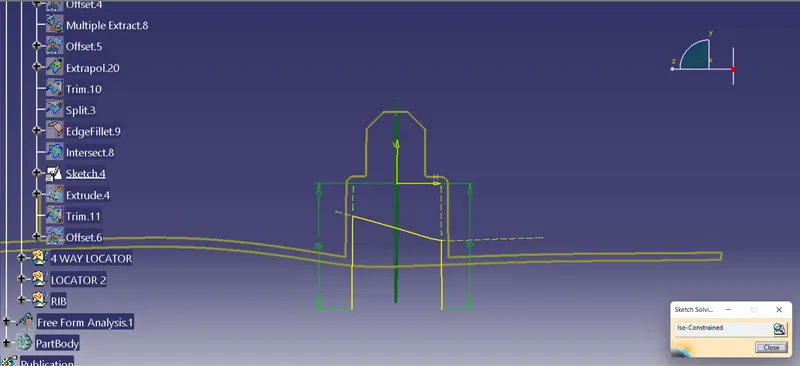
- For the creation of locators sketch the profiles for 4-way locators and pad them with thick feature
- Provide 0.5° draft on their faces and also give chamfer and fillet on the edges
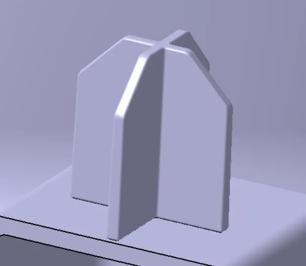
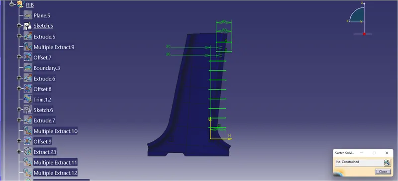
- Sketch line profile for rib and create ribs 50mm apart using extrude and thicken commands
Draft Analysis Report:
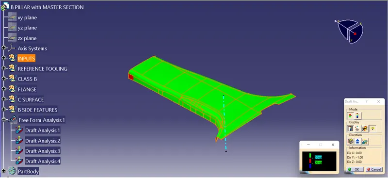
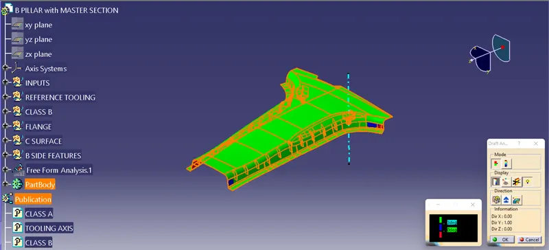
- We need to perform draft analysis on both the class A and solid component
- For the draft analysis go to Insert-Analysis-Feature Draft Analysis and make sure the view mode is on material
- Inline the compass with the Tooling Axis and lock then click on the solid part we will get the draft analysis
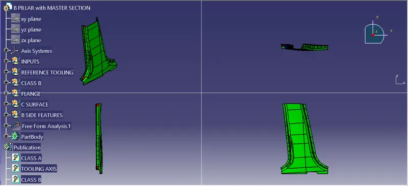
- When we click on the part it will turn green that means the required draft angle is maintained
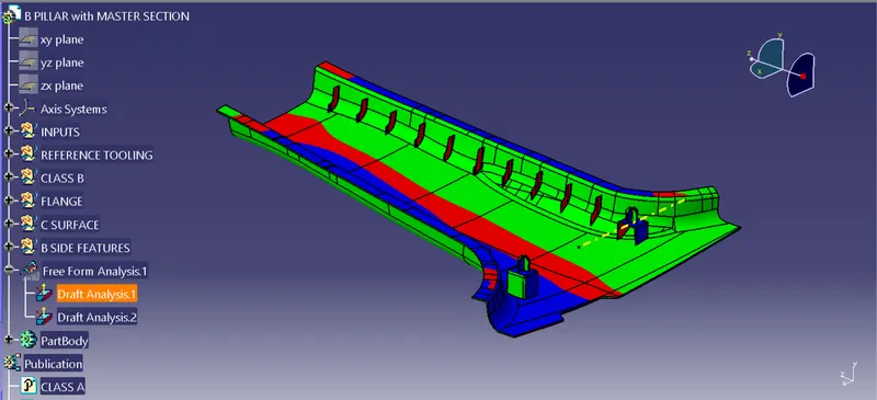
- We can change the value of draft angle from the colour scale table and the model will change the colour accordingly
- We can also analyse the draft at a particular point on the body by moving the mouse cursor on the surface
- Draft Analysis on Class A Surface:
- Draft Analysis on B pillar plastic component:
- Draft Analysis with respect to the side tooling axis:
Picture of the sketches with Sketch solving status’s geometry tab:
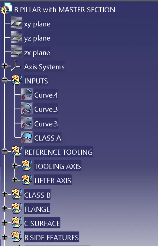
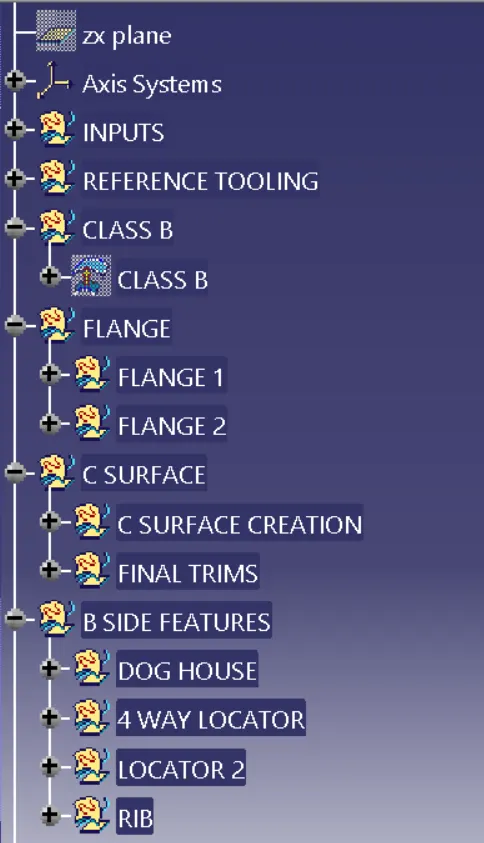
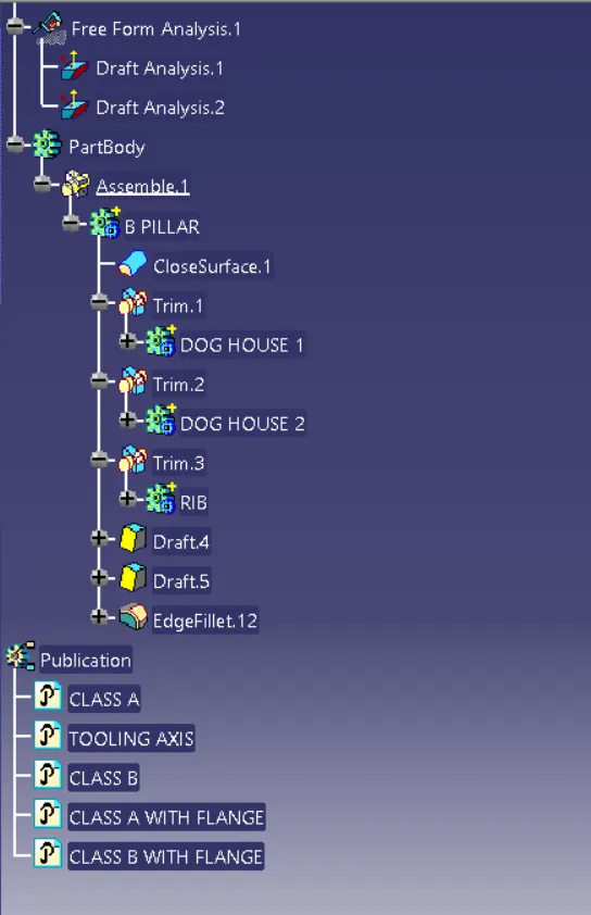
Picture of the Detailed tree structure:
Picture of the 3D CAD: