Week 9 - Project - Master Section Development
B Pillar Design through Master Section Development
Aim: - The main aim of this report is to present the Master Section Development. To create the B pillar Automotive plastic component through the given Class-A surface. Also, to create Flange and B side attachment features on B pillar model using their master sections considering the design rules in CATIAV5 (Computer-aided three-dimensional interactive application).
Objective: -
- The main objective is to exhibit Master Section Development.
- To create the tooling axis for the B pillar model meeting the requirements of the draft angle.
- To explain the bisecting method used in order to create the tooling axis for the B pillar model.
- To create a B pillar Automotive plastic component through the given class-A surface.
- To create Flange and B side attachment features on the B pillar model using their master sections considering the design rules.
- To perform draft analysis on the final component(with B side features).
- To present a proper draft analysis report in detail.
Theory: -
- Master Section: -
Master sections are the guides for design requirements that decide the component packaging after technical (Styling, Concept, or Class-A) surfaces. The master section helps one to decide feasibility, fixation strategy, clearances, packaging, etc. before 3D. It comes under the 3rd stage in the product life cycle as shown in figure 1 after styling class A and before NPDT. It's basically a concept development in BIW. Body-In-white (BIW) is the name given to a car body's sheet when all its components—barring moving parts (e.g., hoods, fenders, etc.), trims (e.g., glass, seats, etc.), or chassis subassemblies—have been welded together as shown in below figure 3. The Master section is also explained in the automotive design layout shown in figure 4.
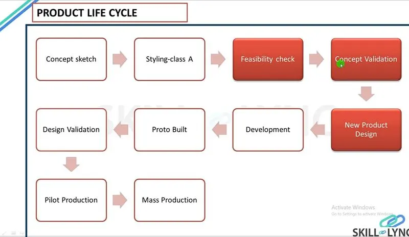
figure 1: - Product life cycle
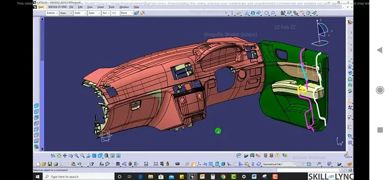
figure 2: - Example of Master section (Cross-section)
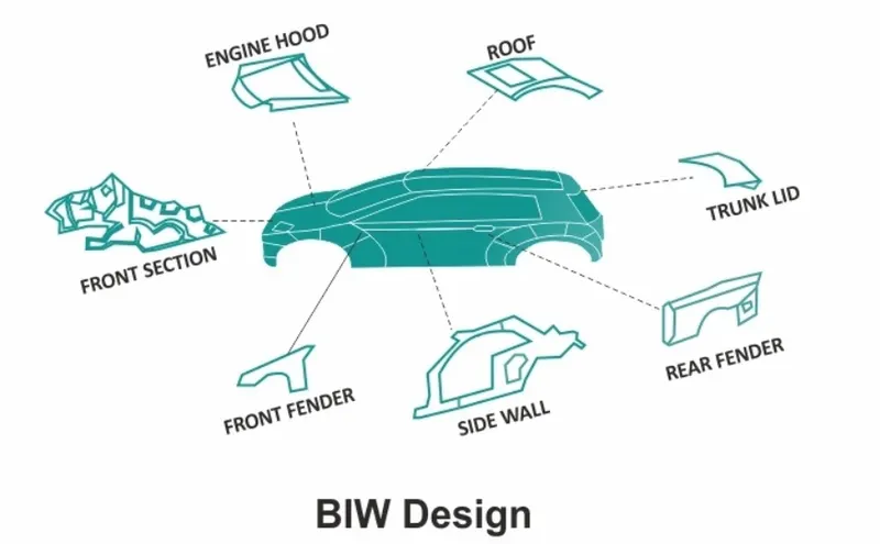
figure 3: - BIW Design
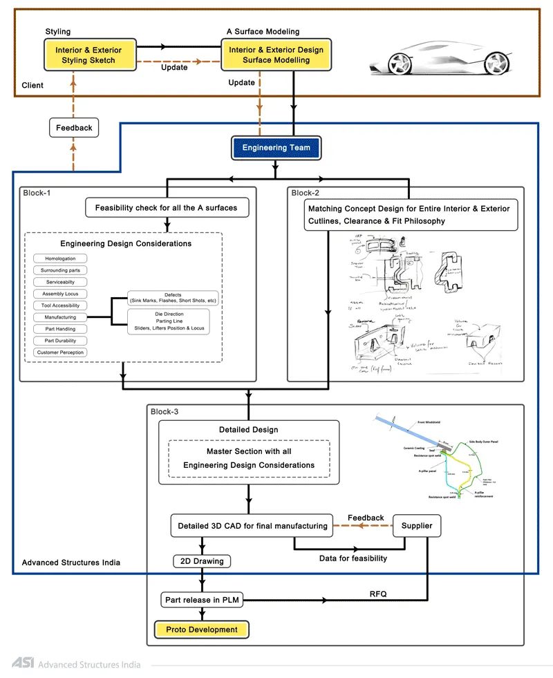
figure 4: - Automotive Design Layout
Let's take an example of an I20 vehicle with a facelift or a new IP and door panel. The industry will not be going to change the whole vehicle by installing something new into it. If size changes then mostly chassis or framework will remain the same. For a new IP, before going for NPDT, the industry will first be going to check the clearances of a new IP with the mannequin, clearances of all functional components with it, their reach zones, packaging, fixation strategy, etc. which all come together under a Master Section. There are many examples such as, while concept-making, the mannequin should reach the infotainment system without any trouble, the up vision of driver should at least 20 degrees from vehicle to avoid interferences, there should no gap and flush, which means that the movement of hands should not hinder by any other component in the car. Before manufacturing and installing a new airbag, the master section will see the clearances for the airbag with other components, its inflammation, fixation strategy, etc. Hence, there are many other rules and checks which are involved under the master section, which have to be accomplished before going on 3D.
2. B Pillar: -
Pillars are the vertical or nearly vertical supports of a car's window area or greenhouse-designated respectively as the A, B, C, or (in larger cars) D-pillar, moving from front to rear, in profile view. The vertical roof support structure is located between the front and rear doors of a typical vehicle as shown in figure 5. It corresponds with the A-pillar located on either side of the windshield at the front of the car and the C pillar which sits on either side of the rear window on a typical sedan.
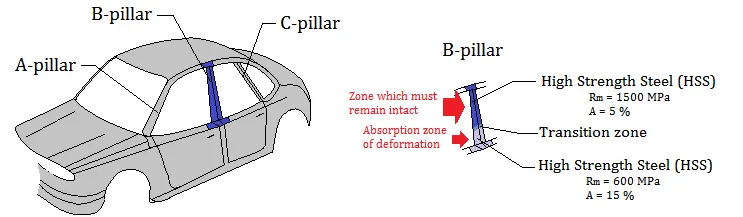
figure 5: - B pillar
In the case of the B (or center) pillar on four-door sedans, the pillar is typically a closed steel structure welded at the bottom to the car's rocker panel and floor pan, as well as on the top to the roof rail or panel. This pillar provides structural support for the vehicle's roof panel and is designed for latching the front door and mounting the hinges for the rear doors. Closed vehicles without a B-pillar are widely called hardtops and have been available in two or four-door body styles, in sedans, coupes, and wagons. Designs without a center or "B" pillar for roof support behind the front doors offer increased occupant visibility, while in turn requiring underbody strengthening to maintain structural rigidity. In the early 1970s, General Motors broadened their definition of "hardtop" to include models with a B-pillar although: "up to then, everybody thought a hardtop was a car without a center pillar."
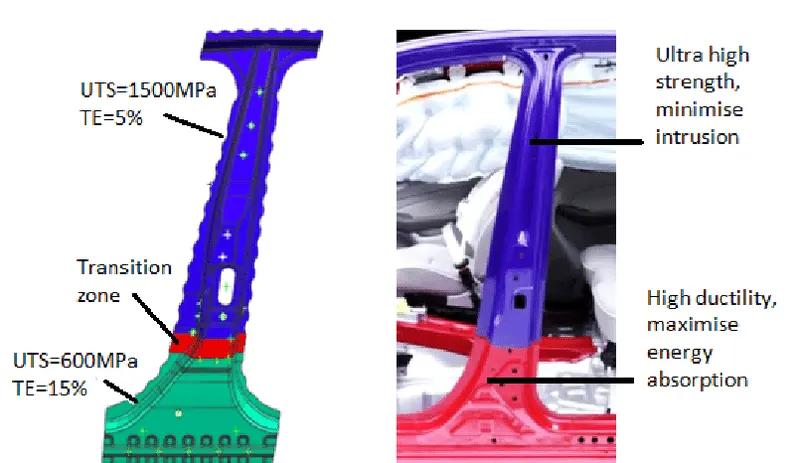
figure 6: - B pillar component with tailored properties
3. Tooling axis creation for B pillar model (with B side features): -
The tooling axis indicates the direction along which the tooling or the manufacturing of the component will be done. In CATIA, the tooling axis is used to create C surfaces using the sweep option. There are many methods for the creation of the tooling axis and bisecting method is one of them.
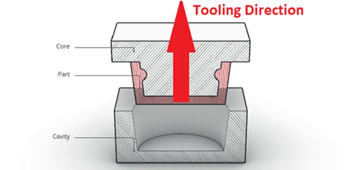
figure 7: - Example of tooling axis direction
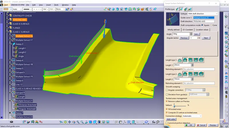
figure 8: - Use of tooling axis in CATIA (C surface)
The steps involved in creating tooling axis using the bisecting method are as follow: -
- Continuity check or quality check of Class A surface
- Selection of best possible tooling direction
- Creating dummy tooling axis
- Tooling clearance for respective directions
- Creating final tooling axis
step1: - Continuity check or quality check of Class A surface
Product designers should check the continuity or quality of the class A surface given by the class A engineer. They should ensure that there are no gaps between the surfaces using the boundary or the join command in CATIA.
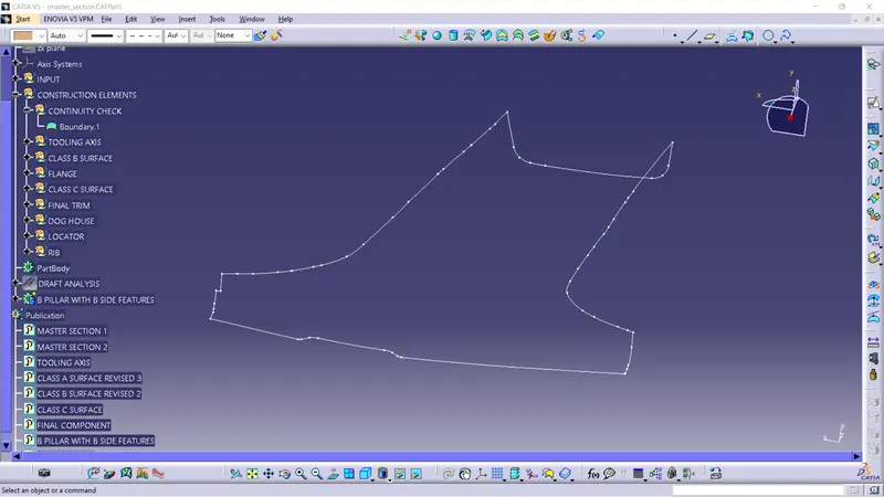
figure 9: - Continuity Check (using boundary command)
step2: - Selection of best possible tooling direction
One can select the y-direction as shown in figure 10 as the best possible tooling direction because it clears all parts in the main tooling and also supports mold manufacturing in an easy way compare to x and z-direction.
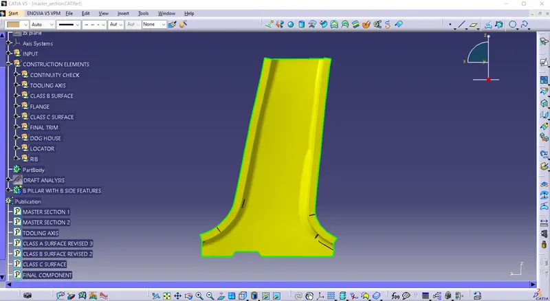
figure 10: - y-direction
step3: - Creating dummy tooling axis
The dummy tooling axis is a line or an axis created at the center along the y-direction as shown in figure 11. The dummy tooling axis is used just as a reference and it is not the real tooling axis.
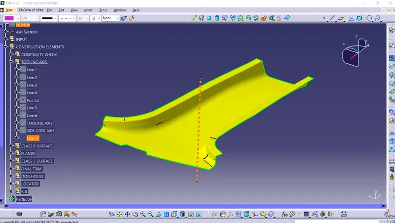
figure 11: - Dummy tooling axis
step4: - Tooling clearance for respective directions
After selecting the main tooling direction, it is important for a product designer to see that all the surfaces along the x,y, and z directions should be clear in the main tooling. Now, the surfaces perpendicular to the tooling axis is quite easy for manufacturing in the main tooling but the surfaces that are parallel to the tooling axis are a little difficult to manufacture in the main tooling. If y-direction is chosen as the main tooling direction then 2 tooling clearances along direction x and z will be created bisecting the surfaces that are parallel to the tooling axis(y-direction) which further will be bisected to form the main tooling axis.
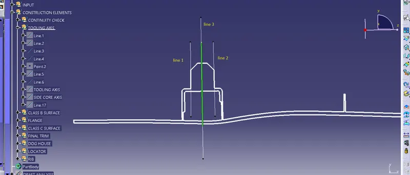
figure 12: - Tooling clearance along x-direction
Line 1 and Line 2 represent surfaces that are parallel to the tooling axis as shown in figure 12 will be bisected to form line 3 which is the tooling clearance along the x-direction
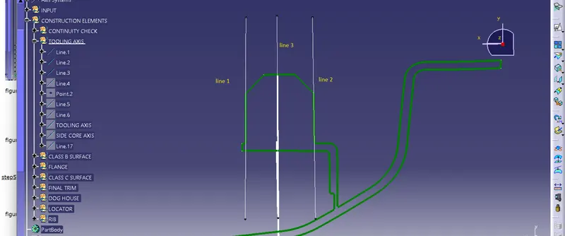
figure 13: - Tooling clearance along the y-direction
Line 1 and Line 2 represent surfaces that are parallel to the tooling axis as shown in figure 13 will be bisected to form line 3 which is the tooling clearance along the z-direction.
step5: - Creating final tooling axis
The tooling clearance lines along the x and z directions will be again bisected to form the main tooling axis as shown in figure 14.
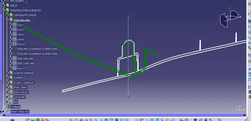

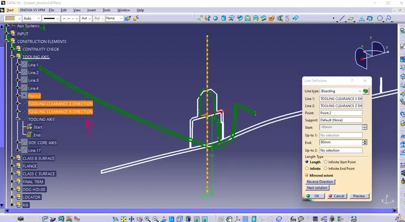
figure 14: - Main Tooling Axis
4. Publication: -
Using the publication option, the important parts of a model are easy to search.
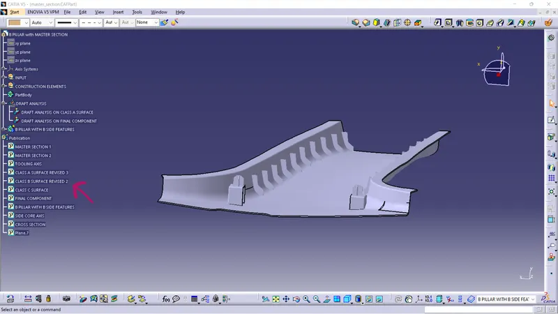
figure 15: - B Pillar Model, Class A, B, and C and tooling axis are easy to search
5. Draft Analysis on B pillar Model: -
Draft: - Draft is providing angles or tapers on product features such as walls, ribs, posts, and bosses that lie parallel to the direction of release from the mold that eases the part ejection.
The draft is required on all parts in the direction of mold movement in order to allow parts to release or eject from the mold properly. The draft is the angle at which the part is tapered to allow it to release. As the part cools, it tends to shrink to the core side of the mold. Adding draft helps the part to release. 3 degrees is the nominal draft. Whereas, 0.5 degrees can also be manufactured at ribs. 7 degrees for the textured faces.
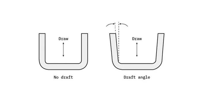
figure 16: - Example of draft
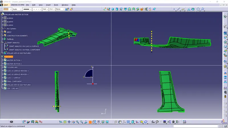
Draft analysis is used to confirm the appropriate draft angle required for the component that is to be manufactured. Quick analysis mode, show or hide color scale, and analysis under the running point are the three main features used in the draft analysis. The color scale shows the draft angle for different colored areas and the analysis under the running point shows the draft angle at different points.
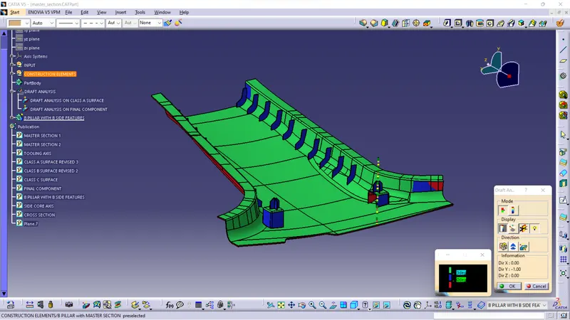
figure 17: - show or hide the color scale
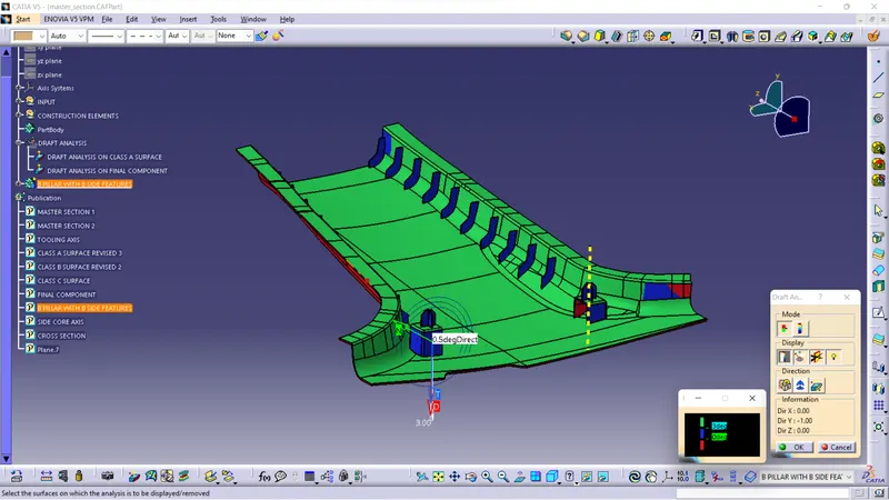
figure 18: - Analysis under the running point
Screenshots of the Draft analysis report: -
- Screenshots of the Draft analysis report for Class-A surface: -
- Image of the complete Draft analysis: -
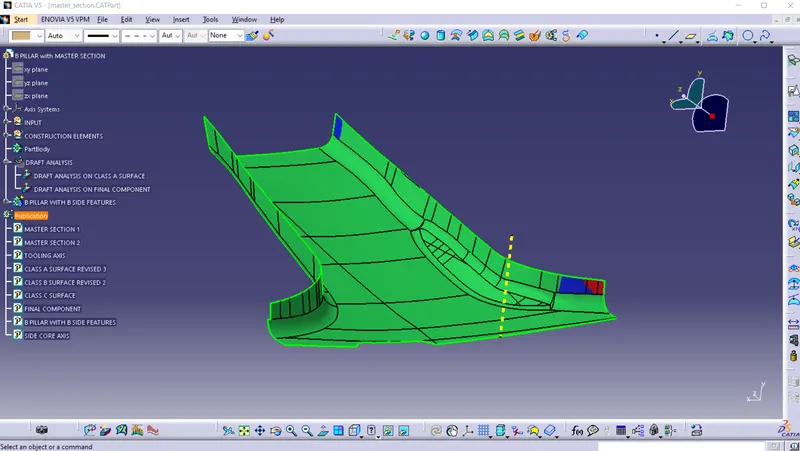
- Images of the color scale variant: -
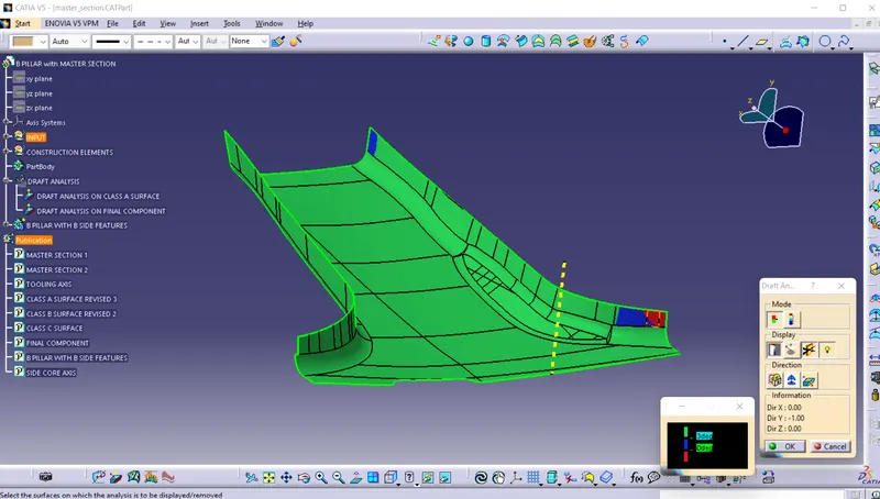
- A model with the proper color code of the draft angle in various orientations (Isometric, Front, Side, and Top View): -
- Screenshots of the Draft analysis report for the final plastic component: -
- Image of the complete Draft analysis: -
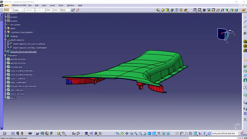
- Images of the color scale variant: -
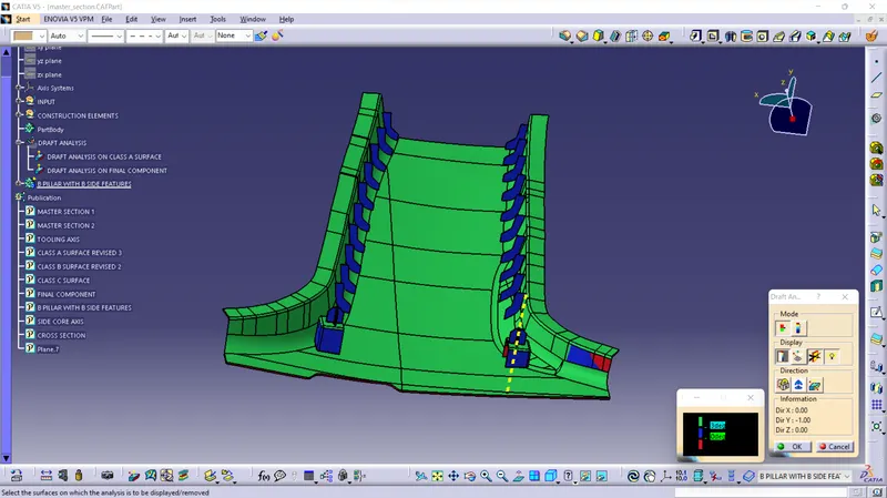
- A model with the proper color code of the draft angle in various orientations (Isometric, Front, Side, and Top View): -
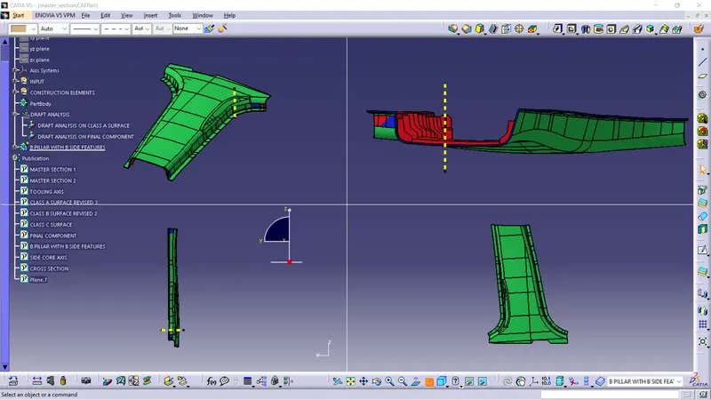
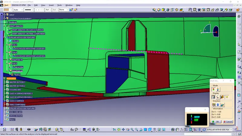
4. Image of lifter analysis: -
Picture of the sketches with sketch solving status’s geometry tab: -
- Sketch 1: -
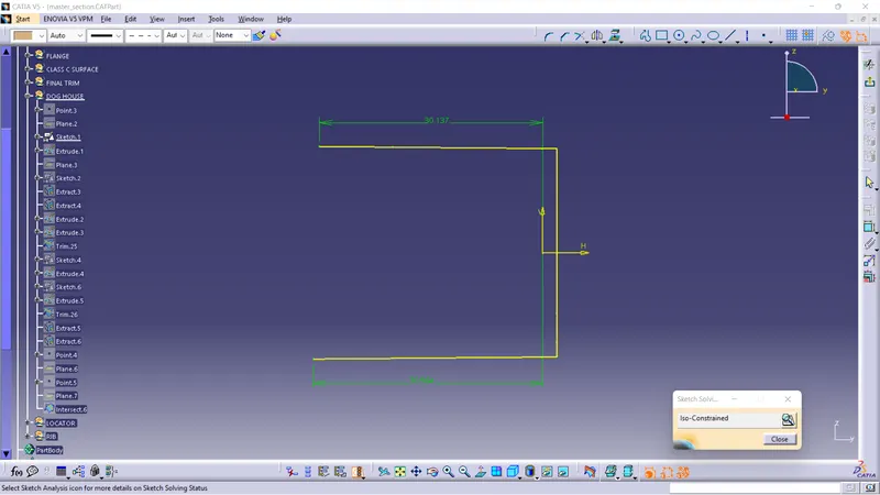
- Sketch 2: -
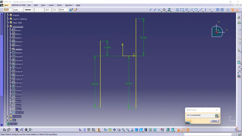
- Sketch 3:-

- Sketch 4: -
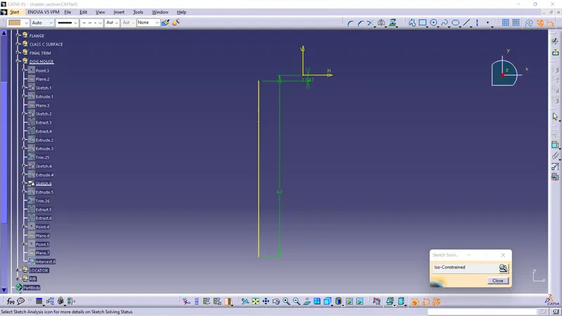
- Sketch 5: -
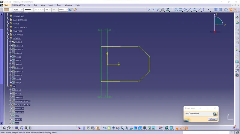
- Sketch 6: -
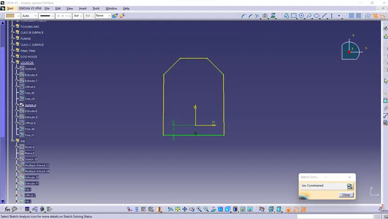
- Sketch 7: -
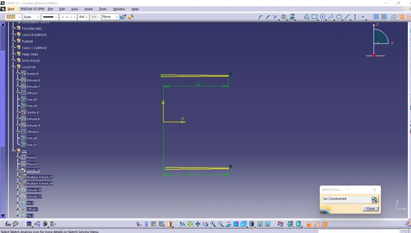
Picture of the Detailed tree structure: -
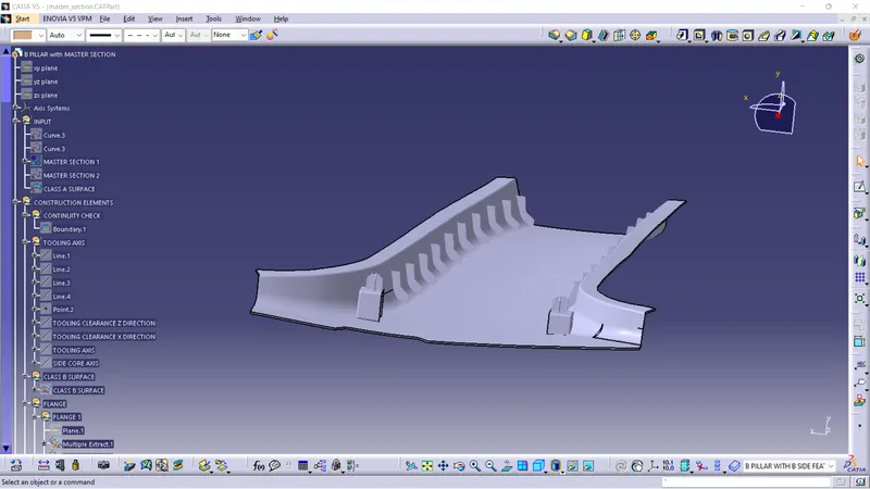
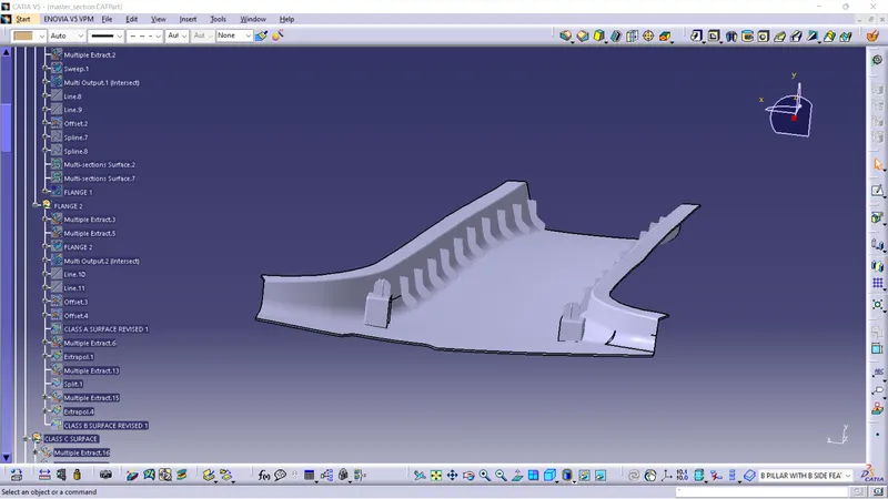
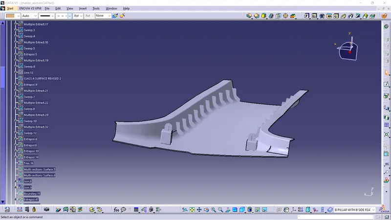
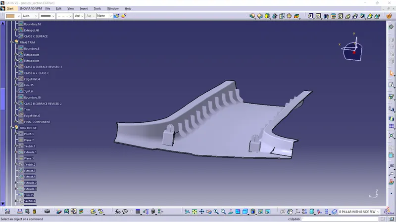
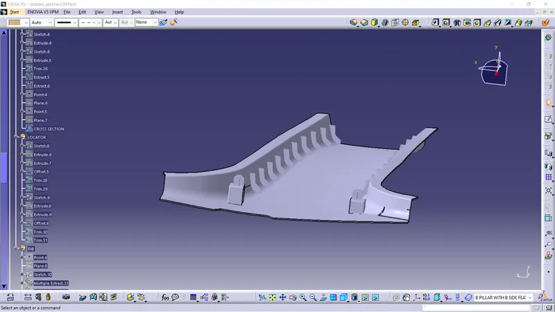
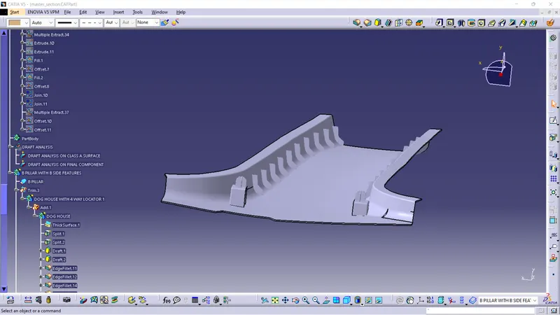
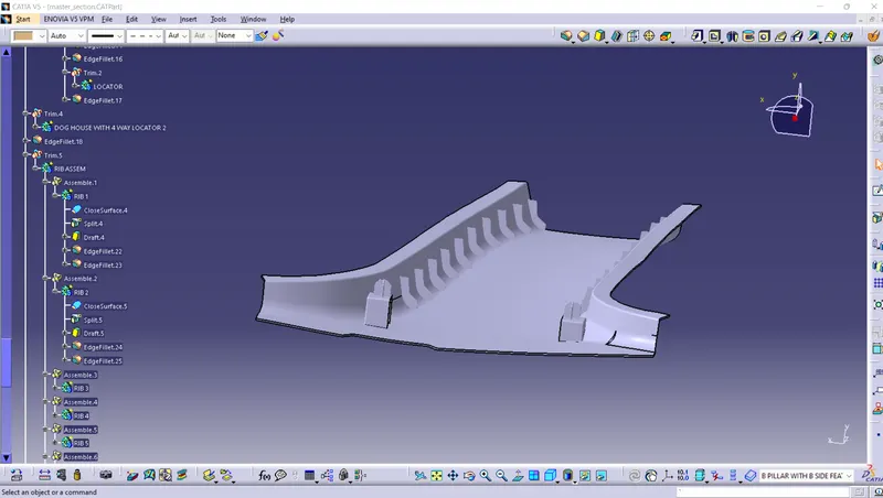
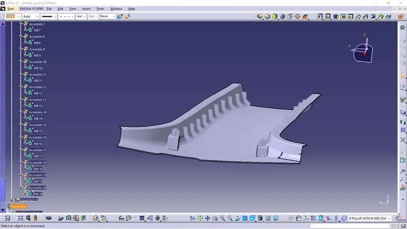
Other images: -
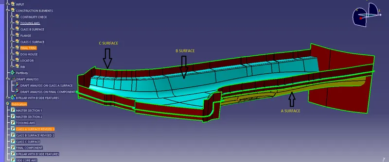
- Class A, B, and C surfaces: -
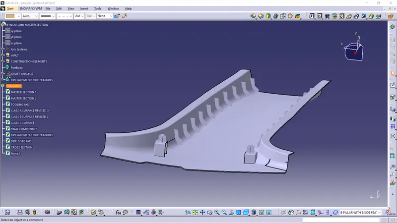
- Final plastic component (with B-side engineering features): -
Conclusion: -
- After creating a feature, one should ensure that the master section is getting matched with the cross-section of the feature made.
- Any error found in class A or the master section should be reported to the respective departments by the product designer.
- If the engineering features are on the B side, still the draft given to the features should be outward.
- B surface can be offset directly using class A having styling fillets.
- Lifters are used when the undercuts are away from the corners of the component.
- Multi-section solid in CATIA is one of the useful commands which is also used to repair surfaces that are not close.