Week 9 - Project - Master Section Development
HELLO SIR,
Week 9 - Project - Master Section Development
OBJECTIVE:-
- To check the boundary of class A surface of B-pillar.
- To create class B surface of B-pillar
- To Create a flange on both sides using the master section.
- To create C-surface of B-pillar.
- To create dog house, locators using master section.
- To create Ribs on both sides of the B-pillar
- To create a Tooling axis using the master section
- to create a lifter axis using the master section.
- To perform the draft analysis.
GIVEN INPUT
CLASS A SURFACE & MASTER SECTION
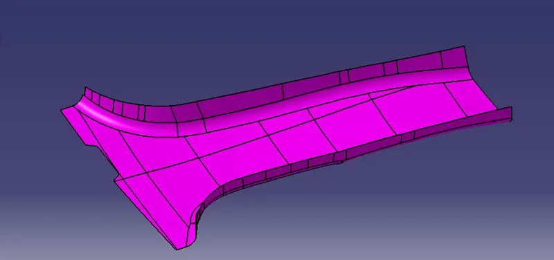
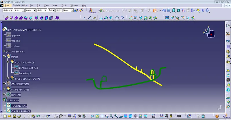
First, I check the connectivity of the (Class A) B-Piller. Click on the join command & boundary command to check, and to ensure that there is no gap between the surfaces.
After that,
Creation of Tooling Axis
Using Extract command to extract the lines of master section curve 3 & 4 then create the point between two curves then go to line command two bisect the curve and then line 1 & line 2 is create then, again go to line command to bisect the two lines then tooling axis is created.
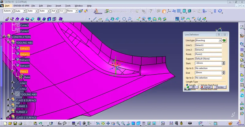
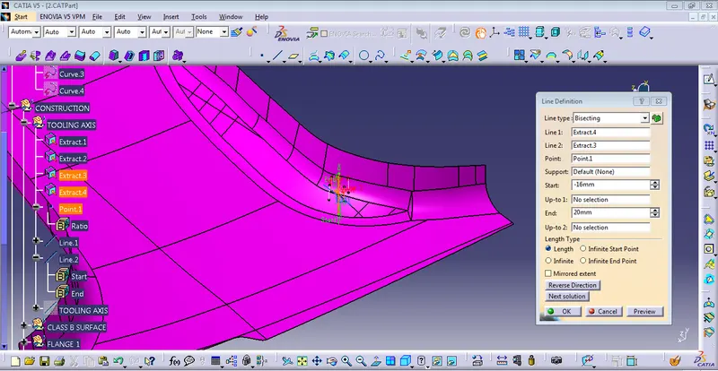
Tooling Axis.
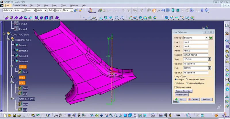
finally, we have got tooling axis then I Published TOOLING AXIS and CLASS A SURFACE
B CLASS SURFACE CREATION
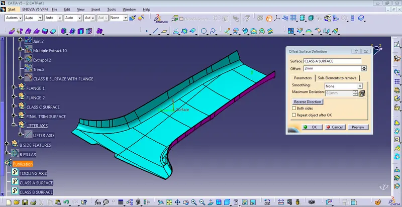
Select the class A surface and go to the offset command to offset 2 mm then i have created class B surface
FLANGES
The flanges are there in the master section so that creates flanges on both sides of the class A surface.
first, we create a plane using the master section then extract the surface of the class A surface then, sweep it.
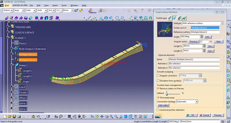
using the same procedure I created another side of the flange
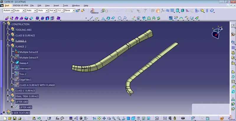
After that, I join flanges with Class A-surface
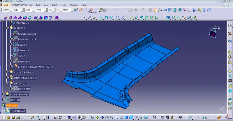
then I got the CLass A surface with Flange and then I Published.
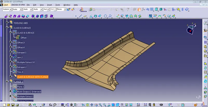
Again we have got class B surface with flange using offset command and extrapolated command.
CLASS C SURFACE
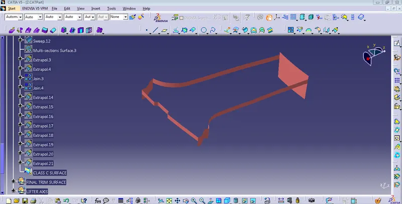
Extract the boundary of class A and then sweep along the main tolling axis and then some edges are not swept then we have extracted the upsweep edges using multiple extract command. then using multi-section surface command to fill the surface.
using trim command to trim the surface, if the surfaces are not intersected then go to extrapolated command to increase the surface .
then we have got the Class C surface.
Then we have to join the CLASS A SURFACE AND CLASS C SURFACE
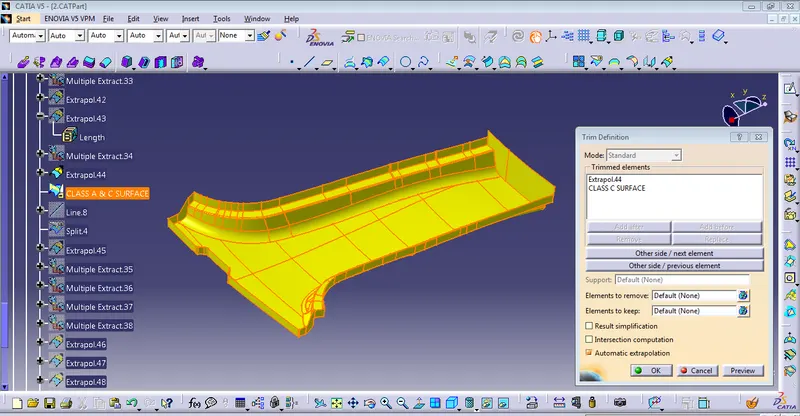
Again we have to join the CLASS A+B+C Surfaces
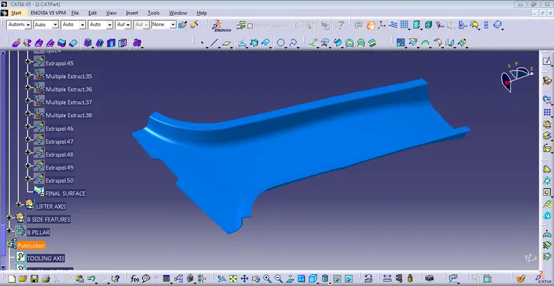
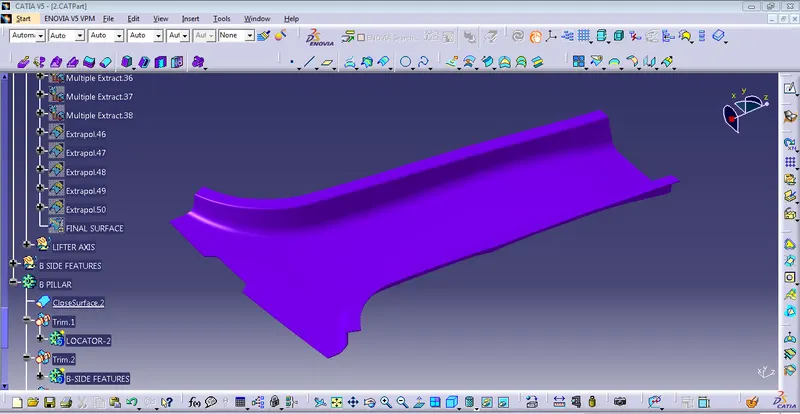
then we have got final surfaces therefore completed A, B& c surfaces were created and joined together.
Also, we created a closed body using the close surface command.
B-SIDE FEATURES
I have created a dog house, locators, and ribs of the B-pillar
DOG HOUSE DESIGN:-
- create a point and plane
- create a positioned sketch and extract the master section.
- extrude the surface along the plane
- again create another plane and go to positioned sketch and extract the curve
- again extrude the surfaces and surfaces are not intersect then use extrapolated command to increase the surfaces.
- trim the unwanted surface.
- insert the new body and thicken it.
from the design rule,
thickness at the junction of B surface and dog house should be 0.4xt
therefore, thickness at junction= 0.4x t
= 0.4x2 = 0.8mm
so that we take the thickness of dog house is 0.8mm
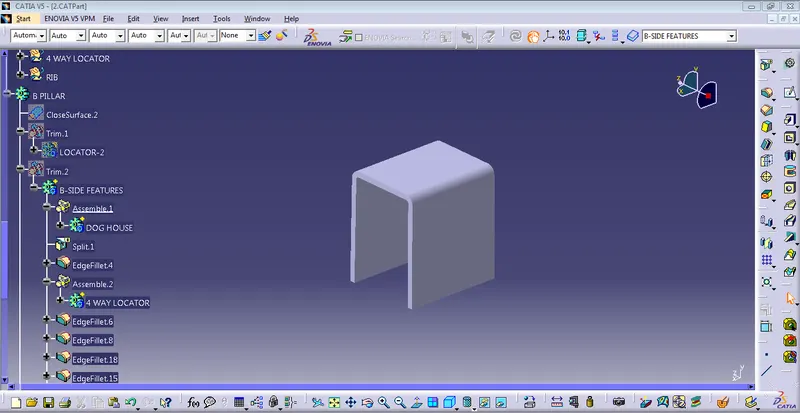
to avoid sink marks to create the reaming part of the dog house using the master section curve we created the surfaces and trim finally we have got the dog house.
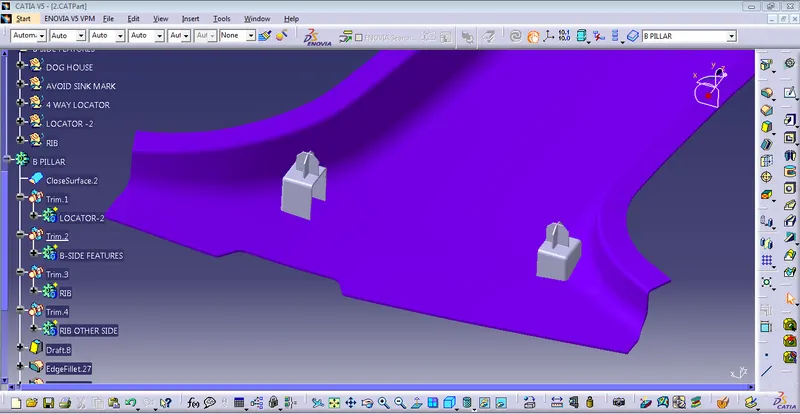
LOCATORS:-
first of all, create a plane using master section curves and then create a positioned sketch and extract the master section curves. then create a new body and go to extruded command and create the locators,
after creating the 4-way locator then provide the draft angle(0.5 degrees) chamfer and fillet of the locators.
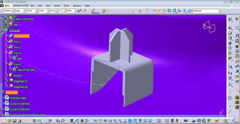
using the mirror command we have created a dog house and locators of the other side.
RIB:-
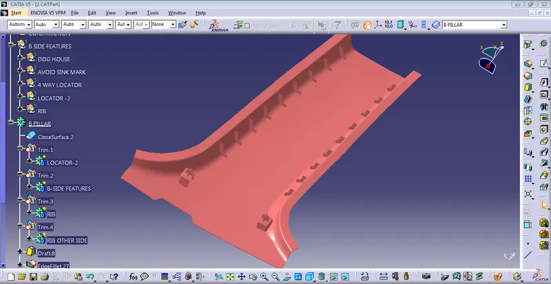
- first of all, create a sketch and go to the extrude command to extrude the surfaces and then, insert the new body and go to thicken command to (0.5 times of wall thickness then we have thickened 1 mm).
- using multiple extract commands extract the surface near about the rib area.
- go to offset command to provide 10 mm
- and to split command to slip the surfaces.
- then we provide the draft (0.5 degrees)
- then we have to provide the fillet
- using the boolean operation to add the main part.
Again using the same procedure we have created ribs on another side.
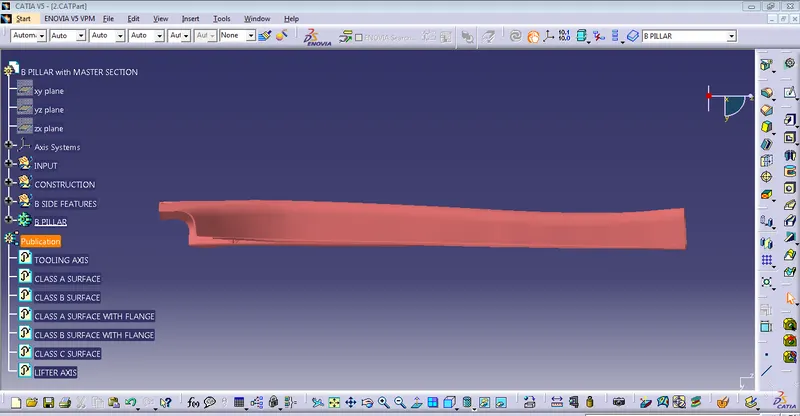
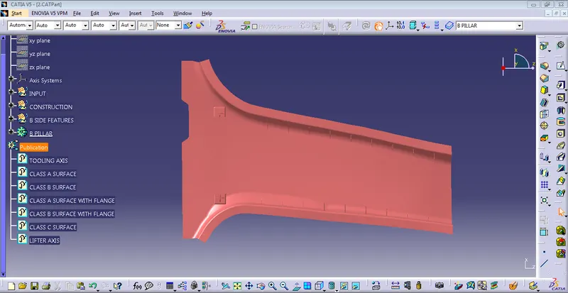
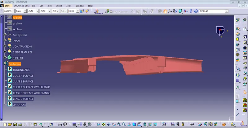
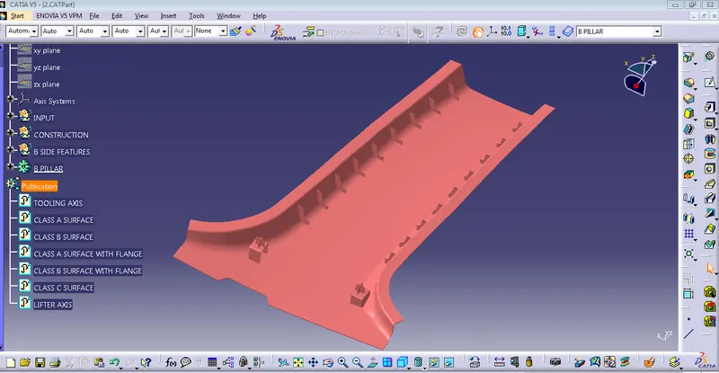
FRONT, SIDE , TOP, AND ISOMETRIC VIEW OF B -PILLER
DRAFT ANALYSIS REPORT:-
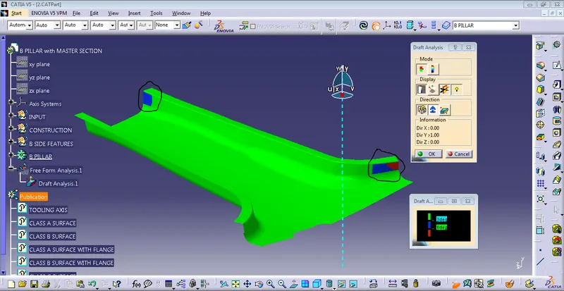
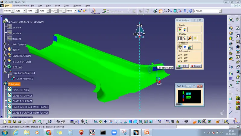
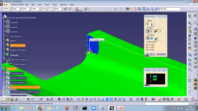
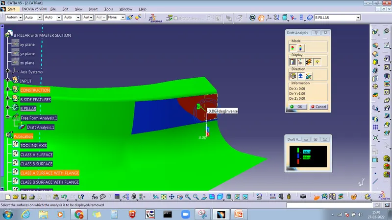
DRAFT ANALYSIS OF CLASS A SURFACE
In this analysis, Class A has three instances where the draft is lower than 3 degrees.
DOG HOUSE & LOCATORS WITH MAIN TOOLING AXIS:-
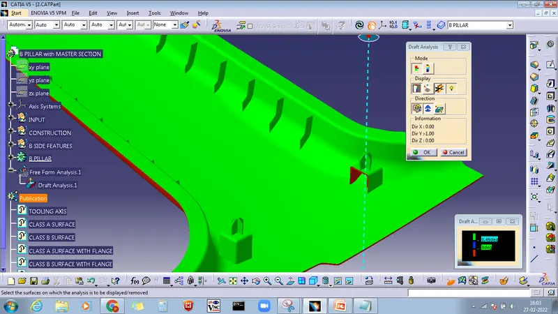
In this analysis, All the faces are clear the main tooling axis at a minimum draft 0.5 degrees.
DOG HOUSE & LOCATORS WITH MAIN TOOLING AXIS:-
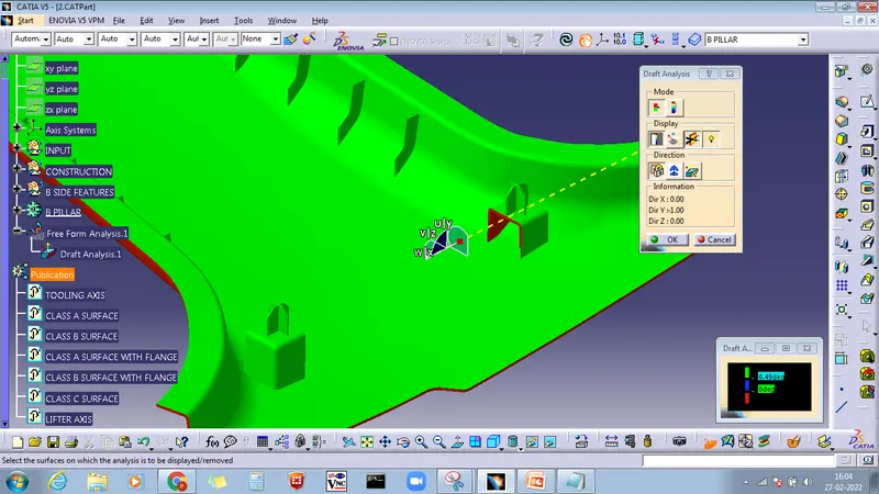
In this analysis, All the faces are clear on the lifter axis at a minimum draft 0.5 degrees.
RIBS:-
In this analysis, All the faces are clear on the lifter axis at a minimum draft of 0.5 degrees.
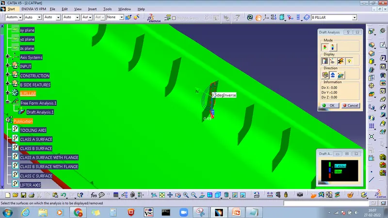
DRAFT ANALYSIS AT 3 DEGREES WITH MAIN TOOLING AXIS.
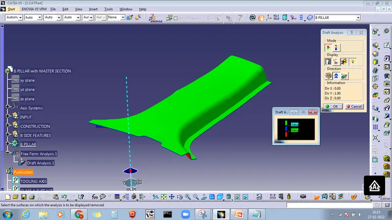
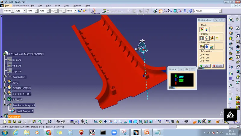
DRAFT ANALYSIS AT 0.5 DEGREES WITH THE MAIN TOOLING AXIS.
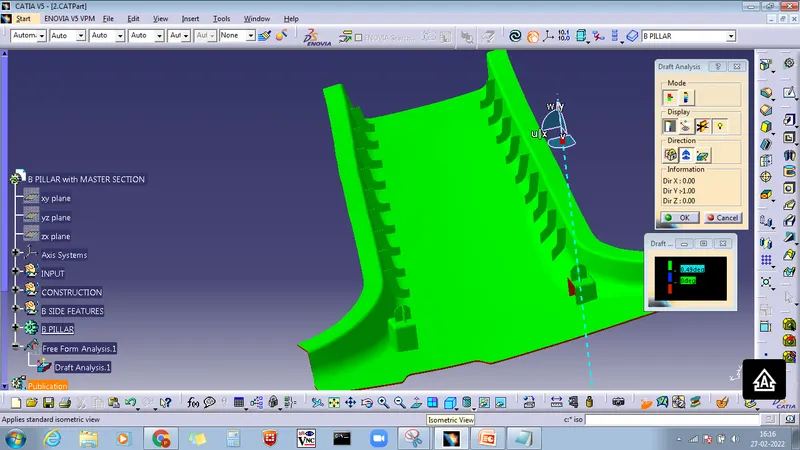
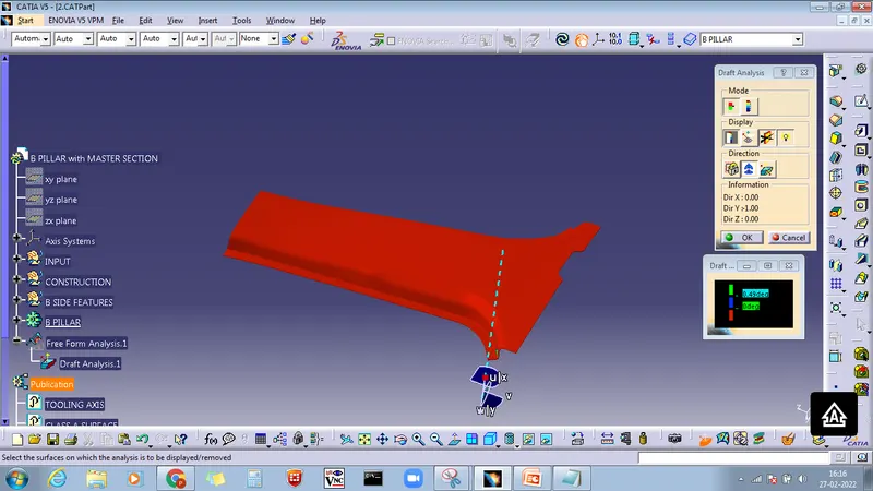
CONCLUSION OF DRAFT ANALYSIS:-
THIS MODEL IS DESIGNED TO DRIFT WITH A NOMINAL ANGLE IS 3 DEGREES ANS B SIDE FEATURES ARE 0.5 DEGREES.
I HAVE ATTACHED THE CAD MODEL & REPORT OF DRAFT ANALYSIS(PPT).
THANKS