Week 9 - Project - Master Section Development
PROJECT
MASTER SECTION DEVELOPMENT – B PILLAR
Aim :
To develop the plastic part from the given CLASS A and master section of B pillar, and to create the closed surface by creating CLASS B and CLASS C surfaces.
To create the proper tooling axis by providing minimum draft to the all surfaces and draft analysis should be done.
Also, to create the engineering attachment features such as locators, ribs and dog house for fixation purpose by following OEM design standards. The fixation features should also meet the draft analysis standards among the side core axis.
Theory :
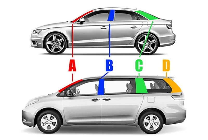
To support the roof of the car, pillars are used. Pillars such as named A-pillar, B-pillar and C-pillar which are referring to car roof pillars, and they are lettered front to back. A-pillar straddle the wind shield, B-pillar are in the middle of the passenger compartment and C-pillars are those at the rear of the passenger compartment. Usually, small cars are having the three number of pillars, In heavy cars such as SUV’s additional fourth pillar (D-pillar) is used. Typically, a B-pillar is located between the front and rear doors of the passenger car.
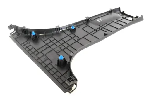
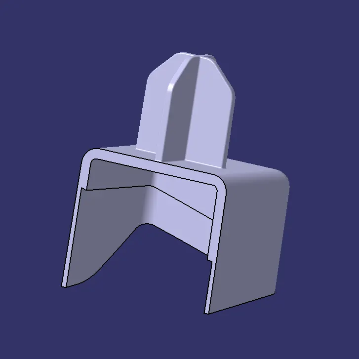
The above picture shows the injection moulded plastic component of the B-pillar. The picture shows the B-pillar with locators and dog house.
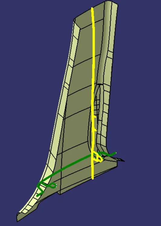
MASTER SECTION:
A master sections are created from the previous version of the part which are used in current developing part. They give reference to some of the features which are indicated in contours.
Steps to be followed:
- CLASS A
- Tooling axis and draft analysis
- B surface and C surface creation
- Closed body creation
- B side feature creation
- Side core axis
- Draft analysis
Procedure :
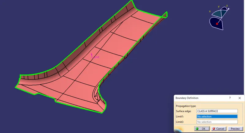
Given B-pillar CLASS A surface with master sections
Check for the open gaps by using the join surfaces or boundary feature
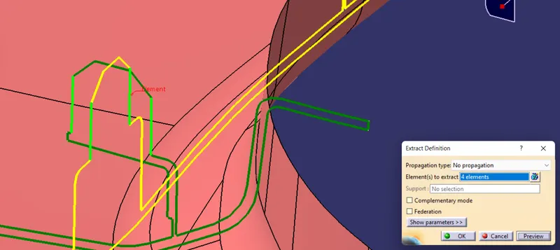
Extract the edges of the locator which is mentioned in the master section. These edges are further used for the creation of the main tooling axis.
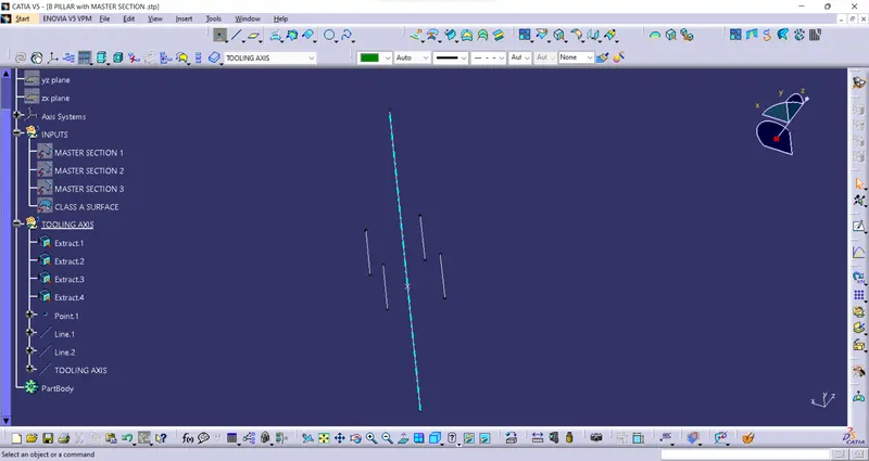
Create the bisecting lines from the extracted edges using the line command, create the point for the reference to the bisecting line in between the extracted lines
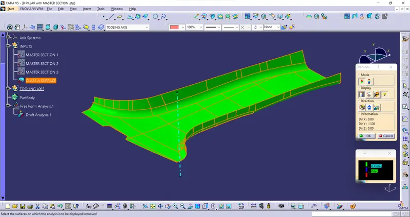
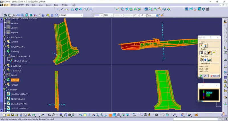
Create the draft analysis on the given CLASS A surface by taking the main tooling axis
B SURFACE -
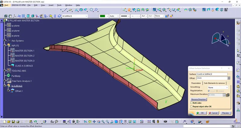
Offset the CLASS A surface to 2 mm thickness, which will our CLASS B surface
Create the plane through the master section by selecting the random three points on the master section
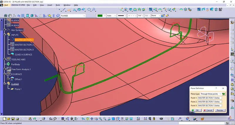
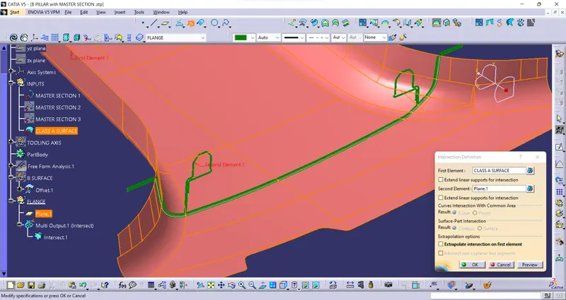
Intersect the plane with the CLASS A surface to create the section contour of the CLASS A
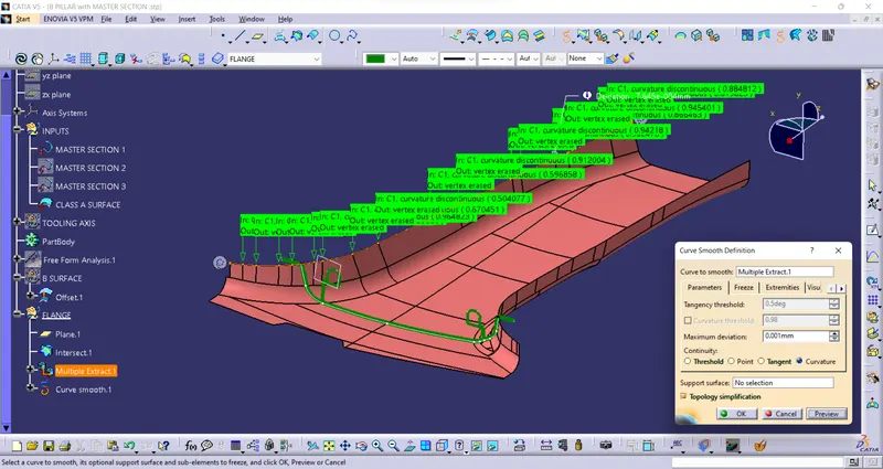
Extract the edge of the CLASS A surface and smoothen the curve which will be used for generating the flanges on the both edges of the CLASS A surface
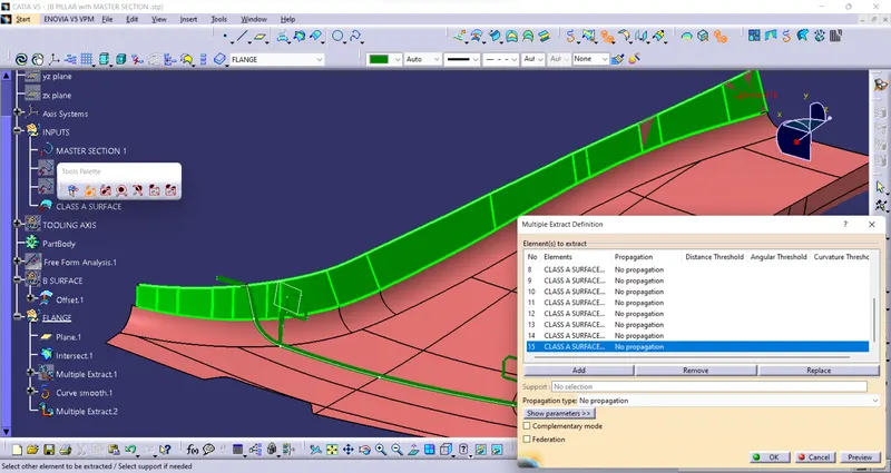
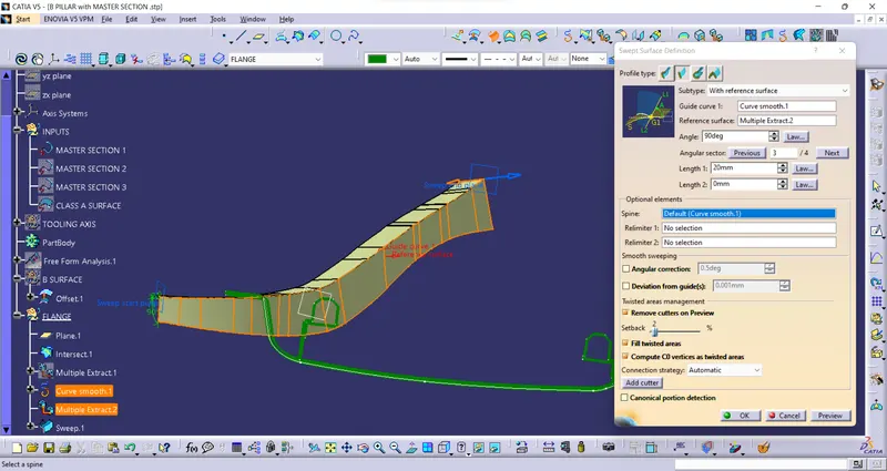
Extract the supporting surfaces which are helpful in creating the sweep surface with reference to the extracted curve
Sweep the curve with the reference surface and adjust the angle to match with the master section
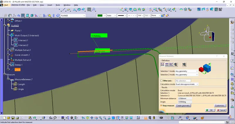
Keep working on the sweep until it lies parallel with the master section by taking measurements between the generated flange and the edges of the master section
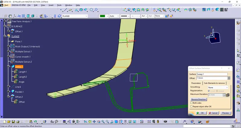
Offset the flange and correct the errors with multisection surface and join all the individuals
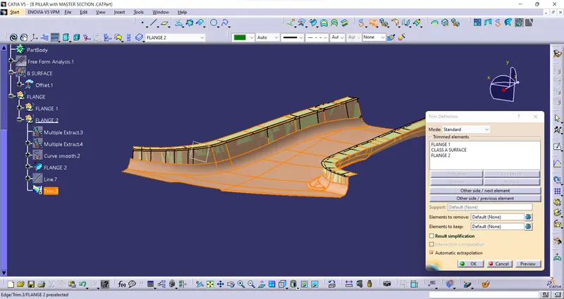
Similarly, create the flange on other side also and trim with the CLASS A surface
Apply the fillet to the sharp edges between the flange and the CLASS A
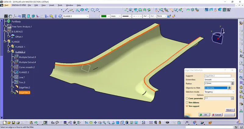
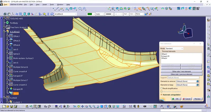
Edges creating error while trimming the off setted flanges with B surface. Rectify them with the multsection surfaces
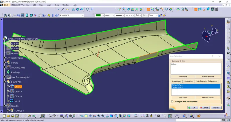
Trim the flanges with the CLASS B surface
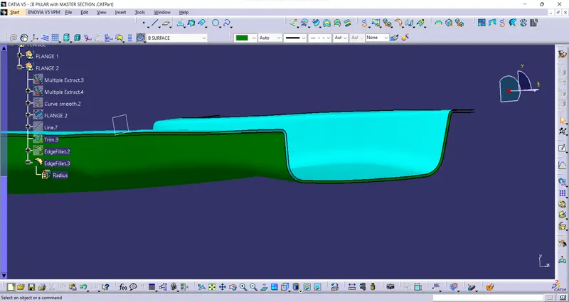
Class A and Class B surfaces are shown in the below picture with an offset distance of 2 mm as measured from the master section
CLASS C surface -
Extract the edges of the CLASS A surface and sweep with the draft direction
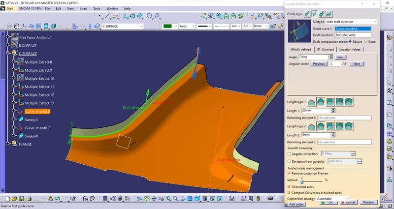
Create the CLASS C surface by sweeping the edges. Class C is created by taking the edges of the CLASS A surface on all side. Extrapolate if needed
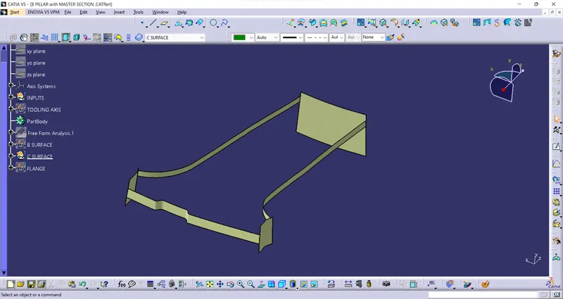
Trim the CLASS C with CLASS A surface. The errors occurred in the trimming are rectified by extrapolating the edges
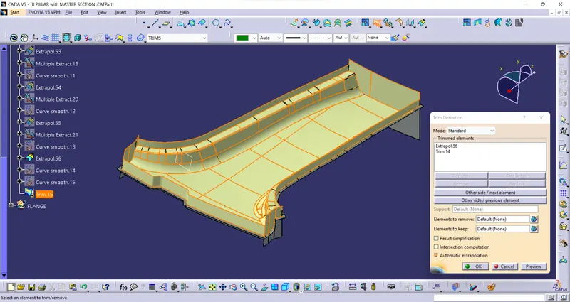
Create the final trim by trimming the unwanted extensions
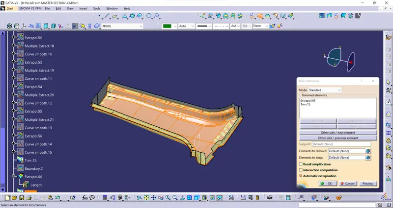
Check for the open gaps using boundary or join, there are no open edges
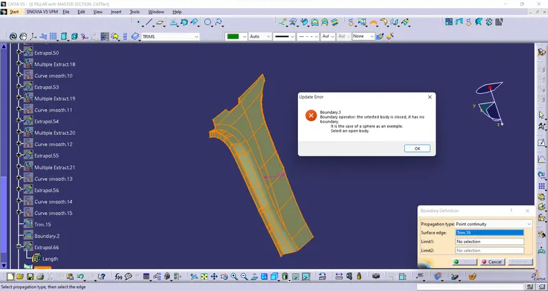
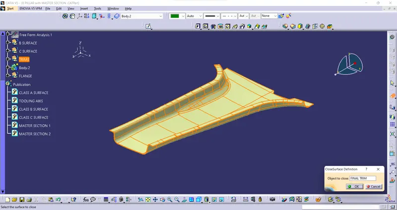
Close the surface and create the final plastic part
DRAFT ANALYSIS -
B SIDE FEATURES -
Dog House
Create a plane on the master section on the mid-point of the master section as shown
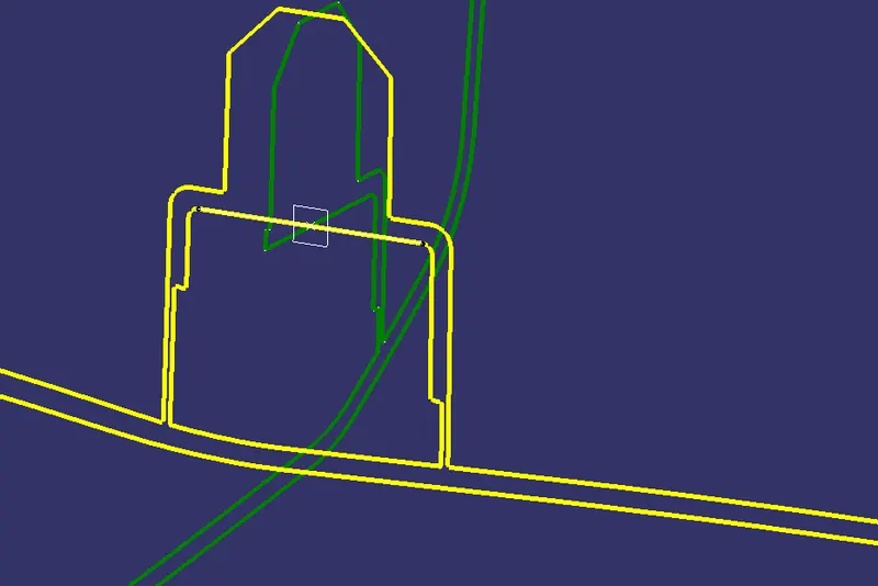
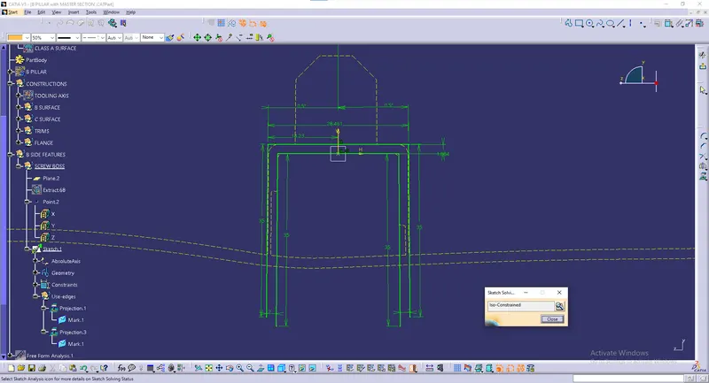
Create a positioned sketch on the plane created and project the edges of the master section. Now, with reference to the projected edges create the outline of the dog house and constrain it
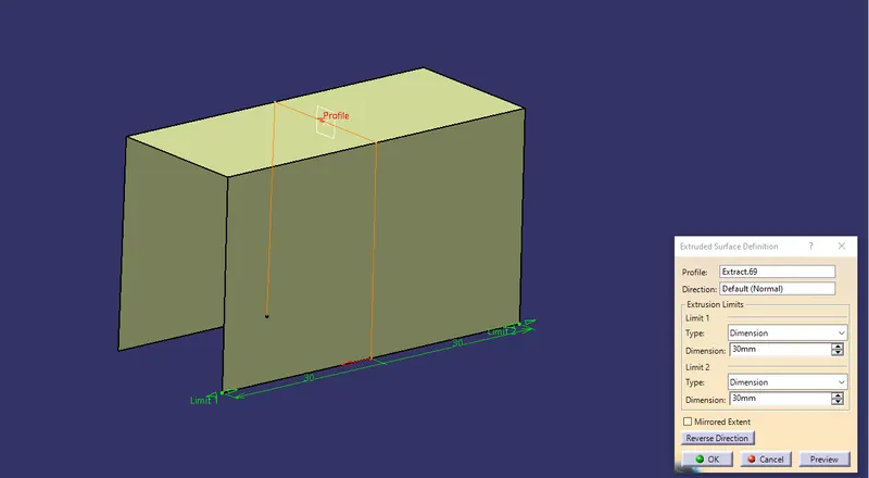
Extract the inner side of the dog house and surface extrude it
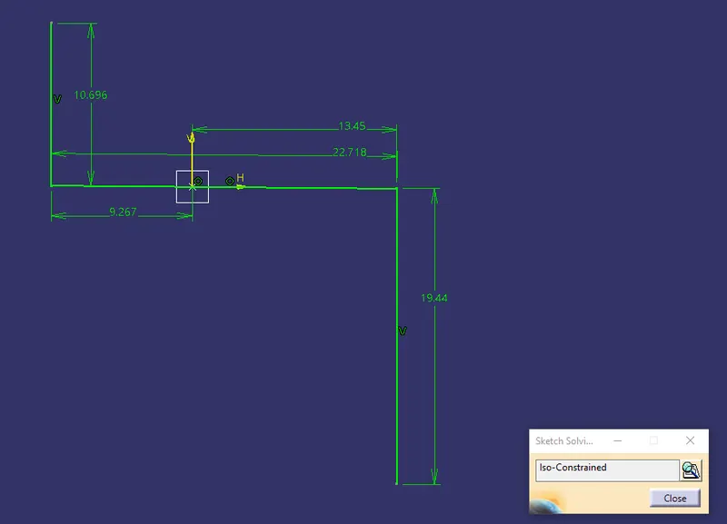
Also do same for the other master section at the same plane
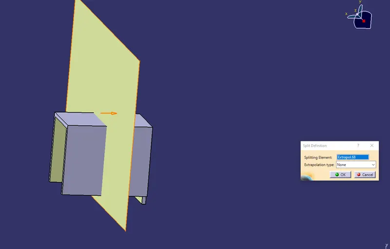
Trim the unwanted surfaces of the extruded edges and thicken the trimmed surface to 2 mm. Then split the thickened surface with the front surface
We have to reduce the thickness of the dog house at the intersection point to avoid sink marks
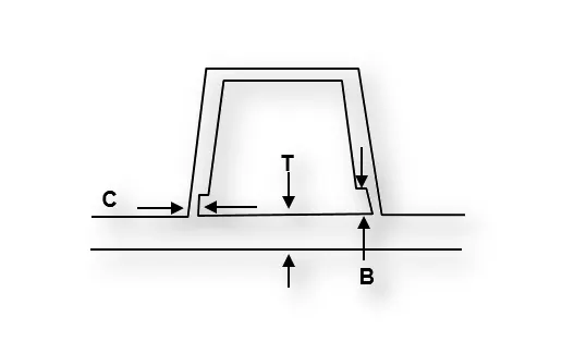
Take B = 5 mm
C = 0.4 x 2 = 0.8 mm
First, split the dog house with the B surface and use the reference of the dog house sketch and create a profile and extrude as shown
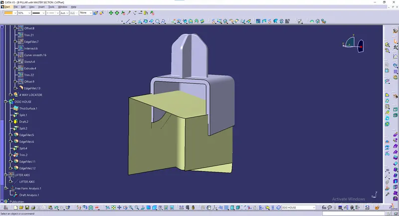
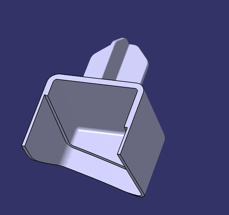
Split the extruded surface with the dog house
4 way locator -
Create the positioned sketch on the top of the dog house and take references from the master section sections. Create the lines for the 4 way locators

Thicken the created line using pad with a thickness of 1.5 mm up to a height of 18 mm from the top of the dog house. Chamfer the edges of the 4 way locator by taking reference to the master sections. Also apply fillet to the edges
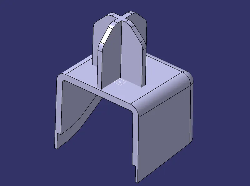
Add with the dog house and apply fillets
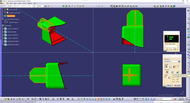
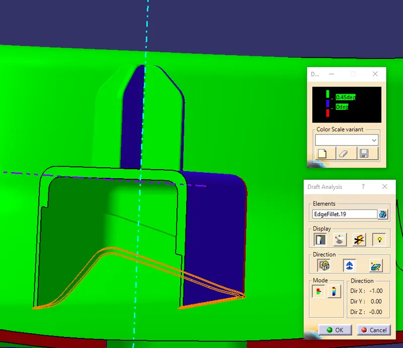
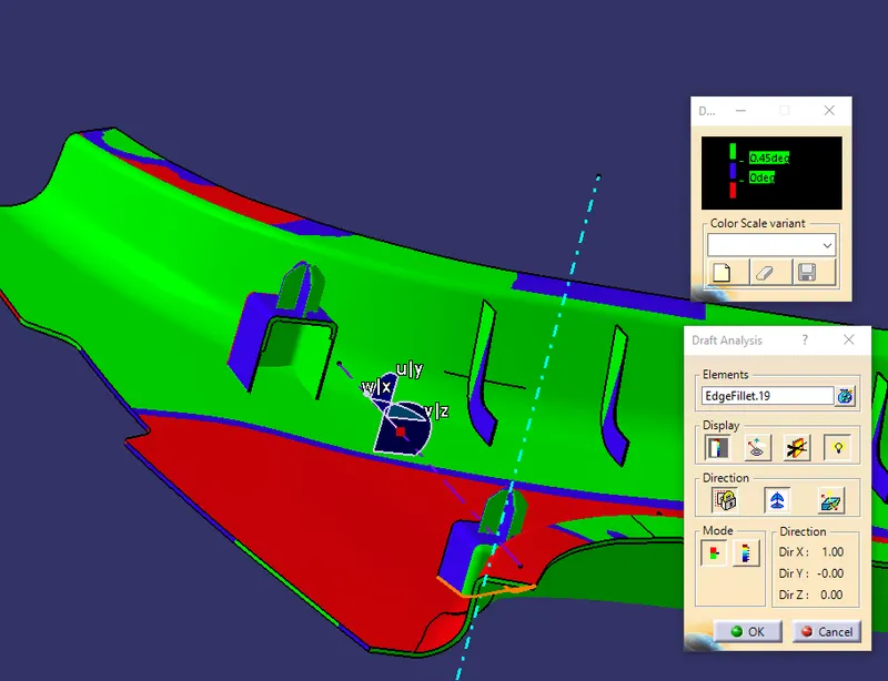
Draft analysis
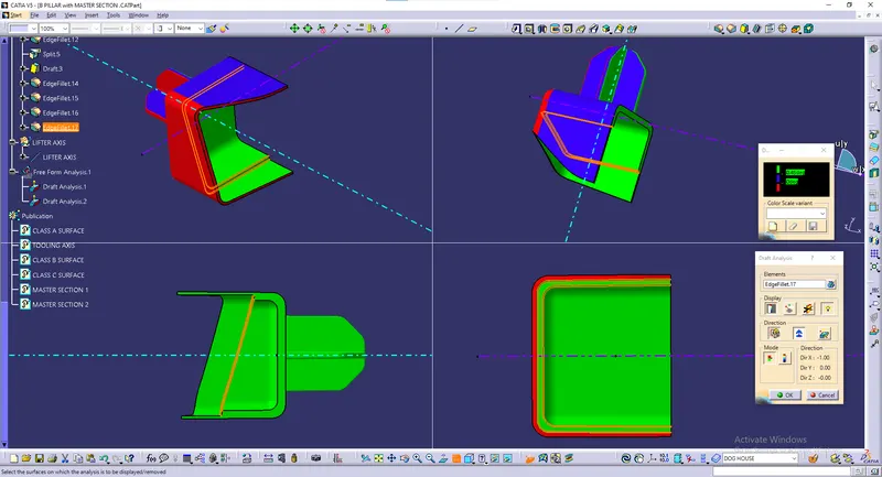
Lifter axis -
Create Lifter axis as reference to the dog house
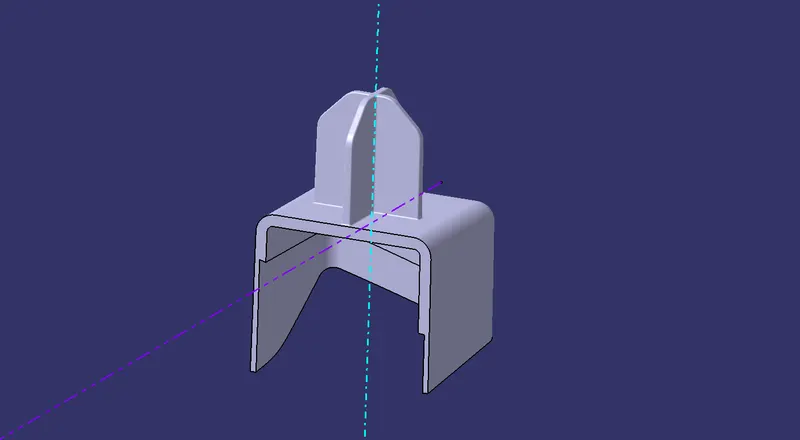
Apply draft to the inner faces and create draft analysis
Union trim the dog house with the B-pillar
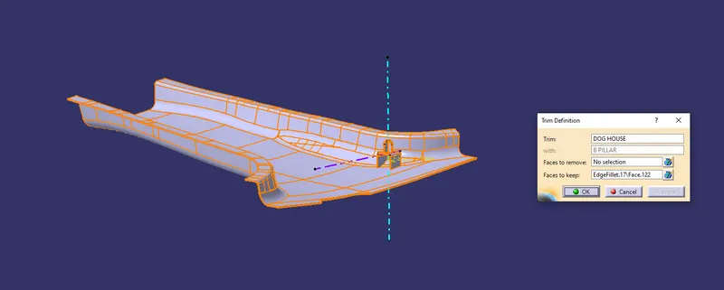
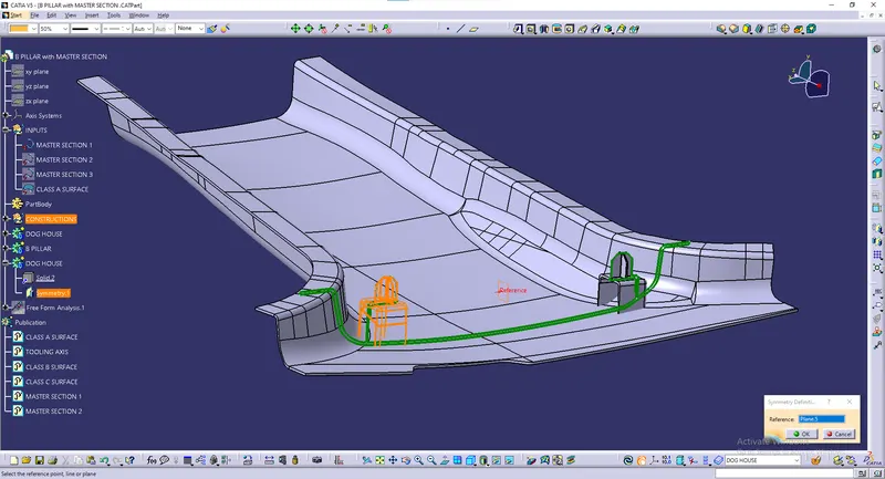
Translate the Dog House by taking reference point and plane, and union trim with B-pillar
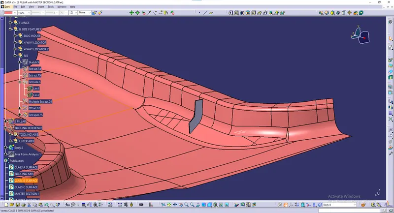
Rib -
Creating Rib using positioned sketch splitting surfaces, draft the faces. Later union trim the rib with the B - pillar
Take the reference curve from the B surface and create the equidistant points in it
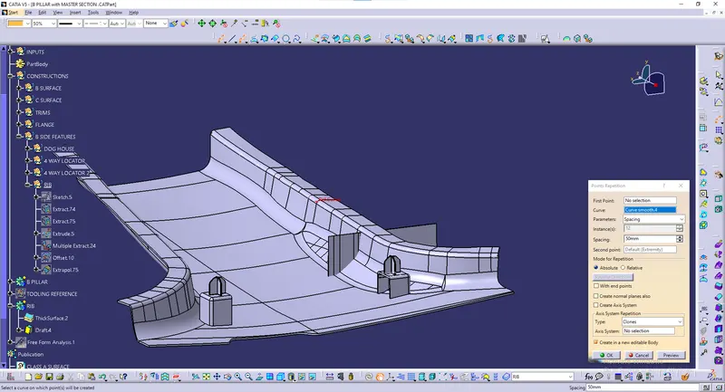
Create the array of surfaces and split with the offset B surface
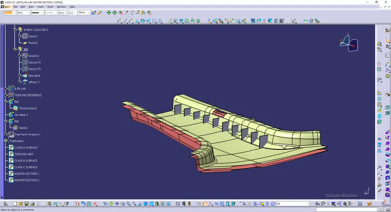
Union trim them with the B pillar
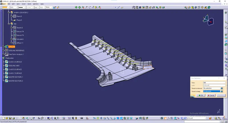
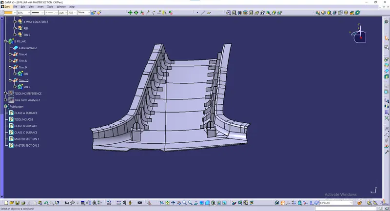
Draft analysis -
Draft analysis along main tooling axis
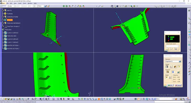
Lifter axis draft analysis
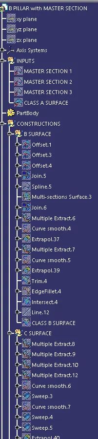
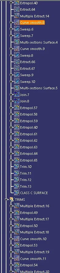
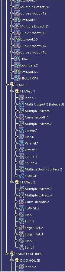
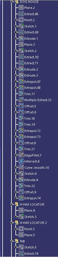
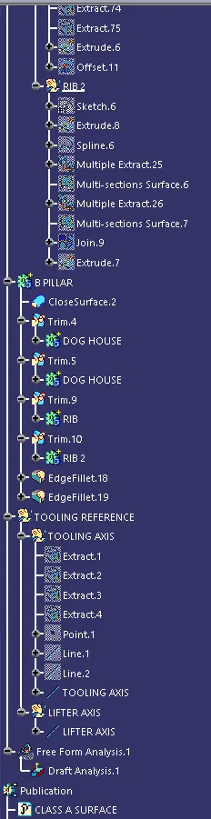
Tress structure :

Conclusion :
The plastic part is developed from the given CLASS A and master section of B pillar, and the closed surface is created by creating CLASS B and CLASS C surfaces.
The tooling axis is created by providing minimum draft to the all surfaces and draft analysis is done.
The engineering attachment features such as locators, ribs and dog house for fixation purpose are created by following OEM design standards. The fixation features should also meet the draft analysis standards among the side core axis.
Thank You