Week 9 - Project - Master Section Development
Aim: To Design Automotive B-piller Trim through Master section and creating a Engineer features.
Master section: The master section help use to decide the feasibility, clearence, packing and fixation strategy of a components before working it in 3D.
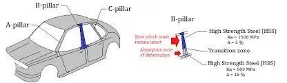
B-piller: In the cars the B-piller acts as a center piller.This piller is actually a sheet metal part which is welded in the BIW(Body in white). The B-piller trim is attached to B-piller and it will improves the Aesthetic look of the car. Mostly the trim is manufacture by the Injection molding process by using Thermoplastic as a material.
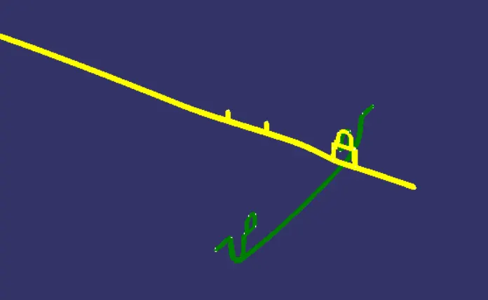
Steps to creating a Main Tooling axis and Lifter axis
- From the master section selecting required line and extracting them, as reference point selecting a point from the extracted line in the provide a midpoint to creeate a point in between them.
- The X direction and Y direction alomg the class A surface were used to create Tooling direction.
- Finally tooling direction is create by using Bisecting the two line and provideing a main tooling axis.
- The tooling axis will determine the direction of class C surface for boundary swept with Draft direction.
- Actually when we viewing from the Tooling axis Normal,all the parts that are drafted should be visible so that it gives rough idea to determine products manufacturing in Injection molding.
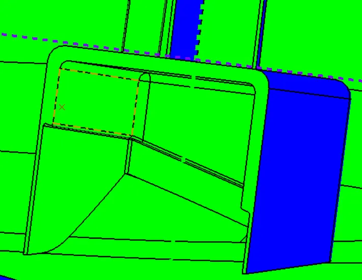
- But in this B-piller moldel there are two tooling direction one is the main tooling axis and one more is side core/Lifter side that is used to eject the parts during injection molding.
- Lifter side is used because here Dog house is created as a Bside feature, so to eject the part.
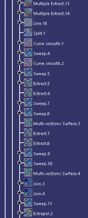
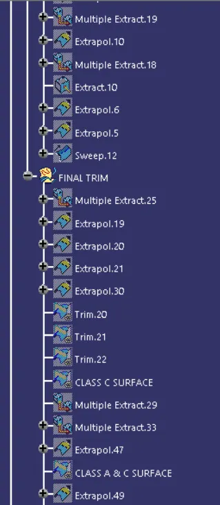
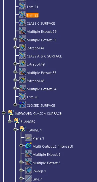
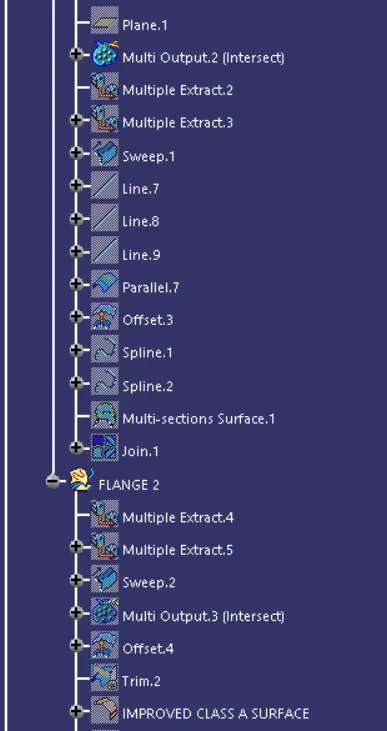
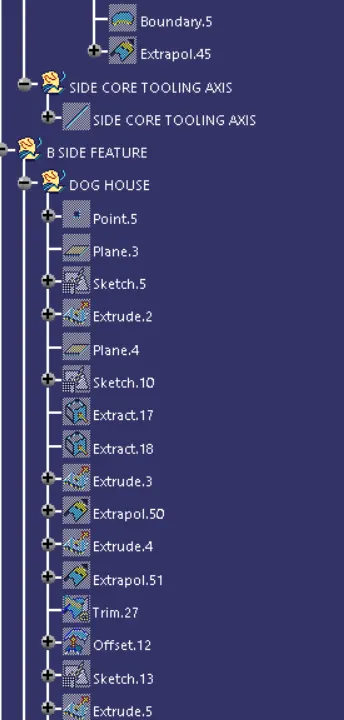
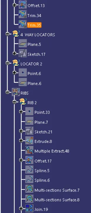
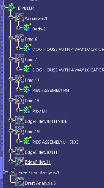
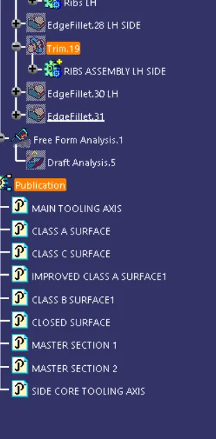
Feature Tree
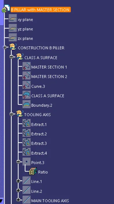
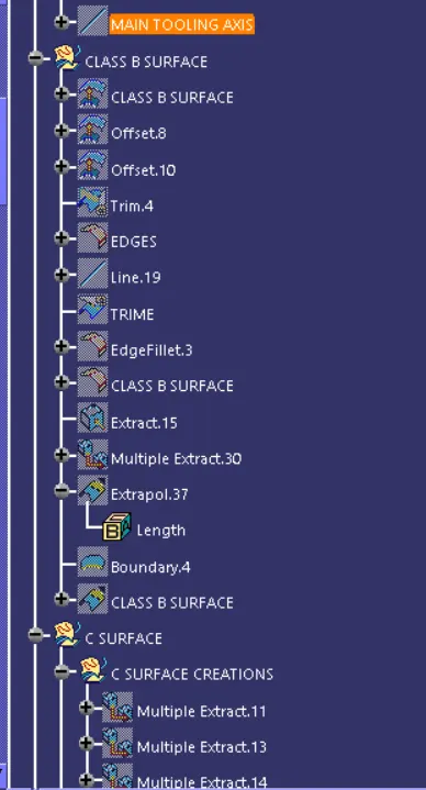
The feature tree involves as Planes, so here we are using a geometrical set by using this what ever we create as sketch section is will be in geometrical set and solid part will be in the Body frame.Finally here Publication is used here we can easily select what we want.
Improved class A surface
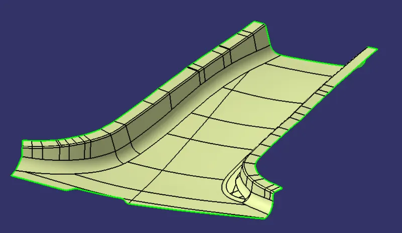
Before start to create the closed surface for the B piller, here we need to check the quality of the given Class A surface. The class A surface should be free from the patchs. If any error or patchs are found first we need to inform the stylish team after that we can correct it.
Class B surface
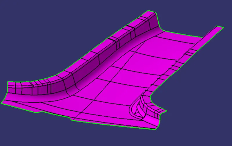
- The next step is to create the Class B surface for the input which is usually the surface where all the Engineering feature are placed on the class B surface.
- The B surface creation is performed by using surface workbench in catia which is offset from the class A surface with dimensional proportional to the thickness of the part.
- In B piller design the B surface is offset 2mm by using Master section , which is the thickness of the part.
Flanges Creation
- According to Master section, Flanges are required for the B-Piller o the both side.
- So here we need to create flanges on the class A surface and Class B surface the design of flanges should be match for give master section.
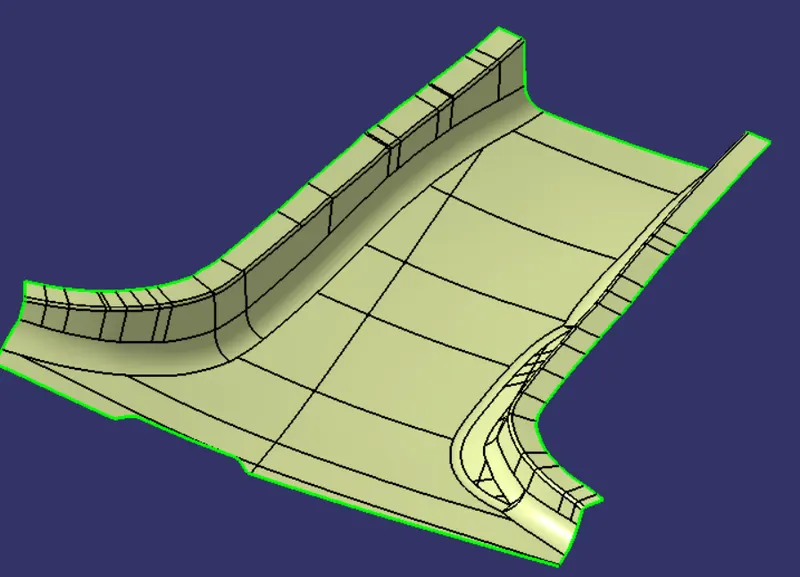
Main tooling axis
The main tooling axis is the direction in which the core moves, during the injection molding core is moved in the cavity and molten plastic is injected in to the mold ,as the molten plastic cools down then core will moves away from the cavity the direction in which the core moves is the tooling direction for the part.
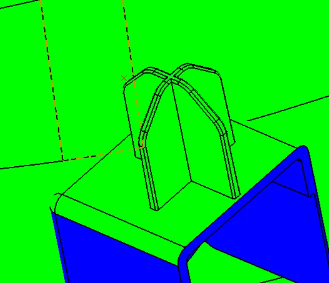
To find the tooling direction here we used a master section for the Engineering feature as 4 Way locator and Dog house.
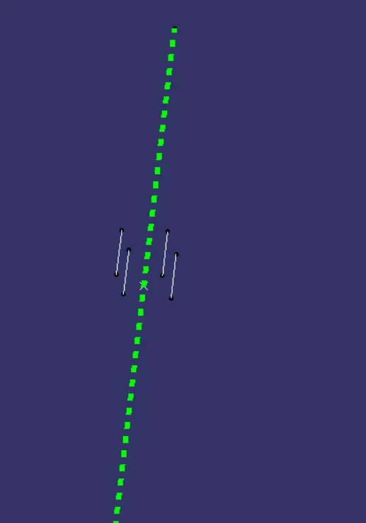
Class C surface
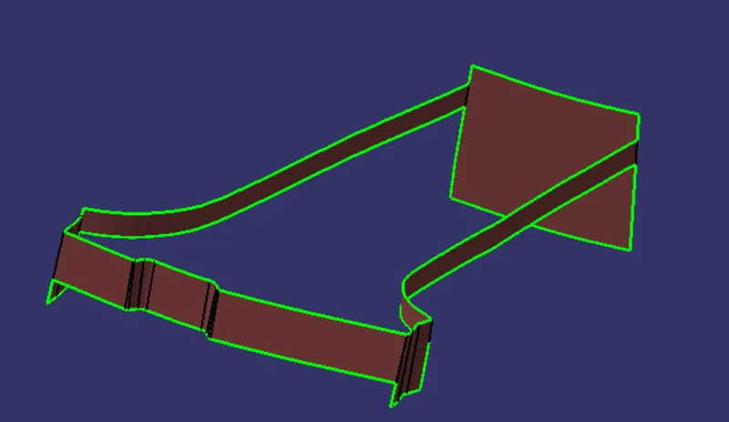
- After the creation of class A & B surface, next steps is to for class C surface which is intermediate between the class A and B surface given the closed surface.
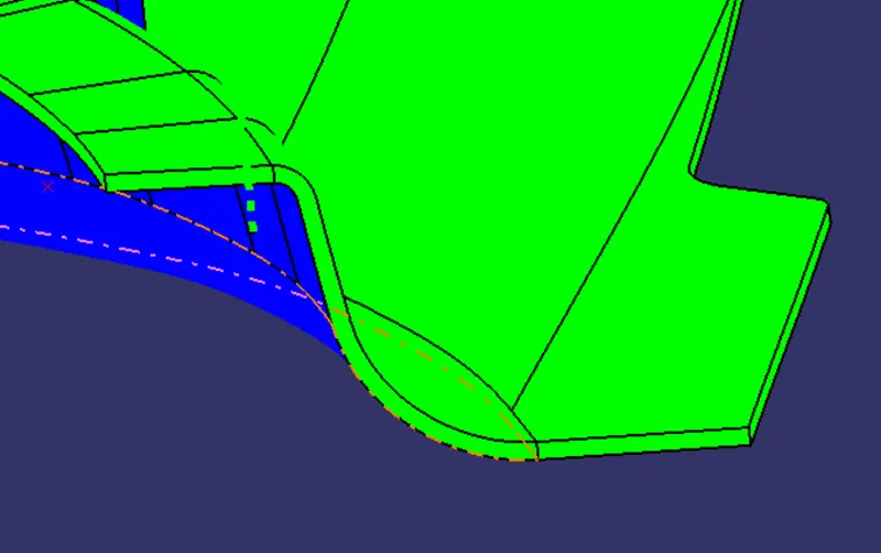
- The class C surface is created by sweeping option using as a profile boundary line of a class A surface which is guid curve with the draft direction, and the direction of sweep is given the tooling direction as we performed earlier.
- The draft angle for the sweep operation is provided which is 3degree , the class c surface must be drafted outward from the A side to avoid the parting line along the Class A surface.
- After creation of class C surface as a sweep then it is joined for Class A surface mearged together.
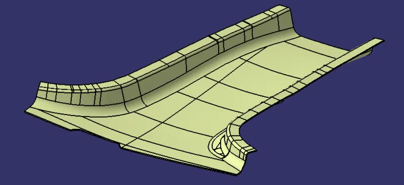
Closed surface
- After the class C and Class A surface has mearged then it is trimed with the meareged part with class B surface to for the closed surface.
- The closed surface is then validated to find the irregularities along the edges and imprefection along the edges .
- The closed surface is the outer skin and finally the part is formed by closed option in the part workbench.
- The final part is measured with the reference with master section to know the thickness of the part and also by using join option it shows the error as it is closed part.
B -Side /Engineering Feature
The Engineering feature are the fixation and location feature that fixs the components, the commonly used B side in the B-Piller are Ribs, Dog house, 4 Way locators.
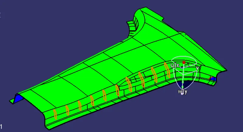
Rib Design:Rib provide a means to economical stiffness and strength in molded parts without increasing overall wall thickness.
- Rib is a thin, wall-like feature typically designed into the geometry of a part to add internal support to walls or other features like bosses.
- Rib increases the bending stiffness of a part. without ribs, the thickness has to be increased to increase the bending stiffness. Adding ribs increase the moment of inertia, which increases the bending stiffness.
- The rib thickness should be less than the wall thickness to keep sinking to a minimum. The thickness range from 40 to 60 % of the material thickness. In the addition, the rib should be attached to the base with a generous radius at the corners
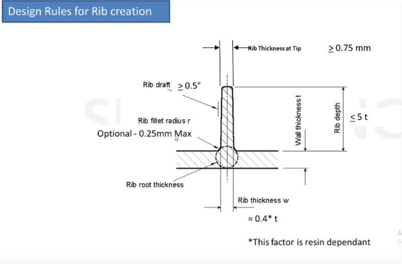
Design rules guidliness for the Ribs
- Rib wall thickness should be 0.4*thickness of part.
- The draft angle of the rib should be 0.5degree.
- The top height of the rib should be at least 0.75mm thick to allow the molten plastic.
- The thickness of the rib, fillet radius, Draft angle, rib root thickness are measured as per design specification.
- The Height of the rib should be 5*thickness of part but here the as we follow as per design rules the rib will be too short so here we not considered.
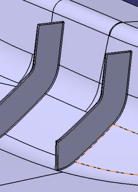
But here the height of the Rib is more then the Design rule guidliness , because as per design rule Height is 5*Thickness of the part as we followed design rule it will be too short.
Dog House
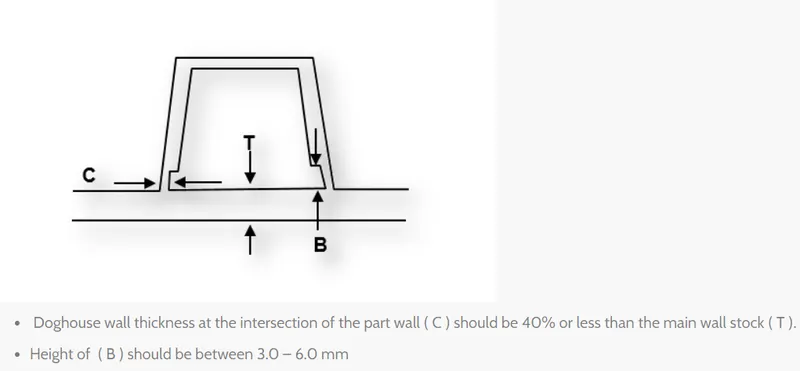
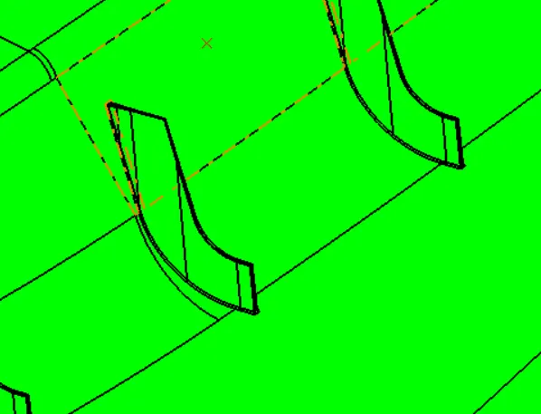
Dog House is an engineering feature used in the plastic trim design. Dog houses are used as supporting features. Sometimes other engineering features like snaps, locators. are mounted on them to increase their strength.
Dog houses are subjected to draft analysis to prevent breakage of the components during the ejection mould cavity. Dog house and other engineering components are built on the class B- Surface
Draft Analysis procedure
- The part created has to be in Material Modein display frame
- Then enabling the composs direction place them on the tooling direction.
- Lock the direction applied that fixs the composs and mode dialog box is formed by snapping at any point on the part.
- Through the colour code the draft analysis is formed.
- Then running point analysis is used to know the degree on the part wheather it is in positive or Negitive.
Draft Analysis for Class A surface
Draft anaysis is used to check the manufacturing feasibility. Draft analysis will check the surface with respect to the tooling axis, as we know for the injection molding the draft angle on the surface should be greater than or equal to 3degree if it is negative or less than 3degree it leds to bit difficulity to manufacturing the part.
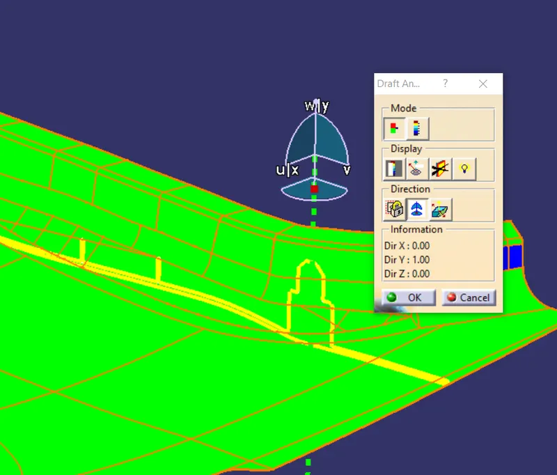
Draft Analysis for B-piller
Class B surface
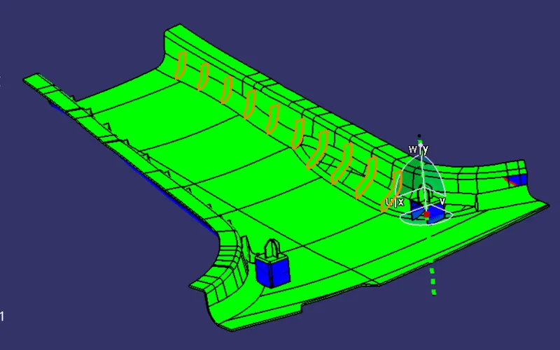
Class A surface
Class C surface
B -Side feature
4-Way Locator
Ribs
Dog House
By using a Side core axis inside the Dog house is manufacturable
Feature Tree
Conclusion
- The B-piller trim is created using a generative shape design workbench.
- The model is designed draft with nominal angle is 3degree and B side feature are 0.5degree
- The closed body of the model is created using close body command in part design workbench.