Week 9 - Project - Master Section Development
MASTER SECTION DEVELOPMENT
OBJECTIVE:
To design a B pillar along with supporting features using the master section given by following the plastic design rules.
REQUIREMENTS:
- Tooling axis creation.
- Draft analysis for class A.
- Create class B & C surface.
- Design engineering features.
- Draft analysis on the final part.
INPUT:
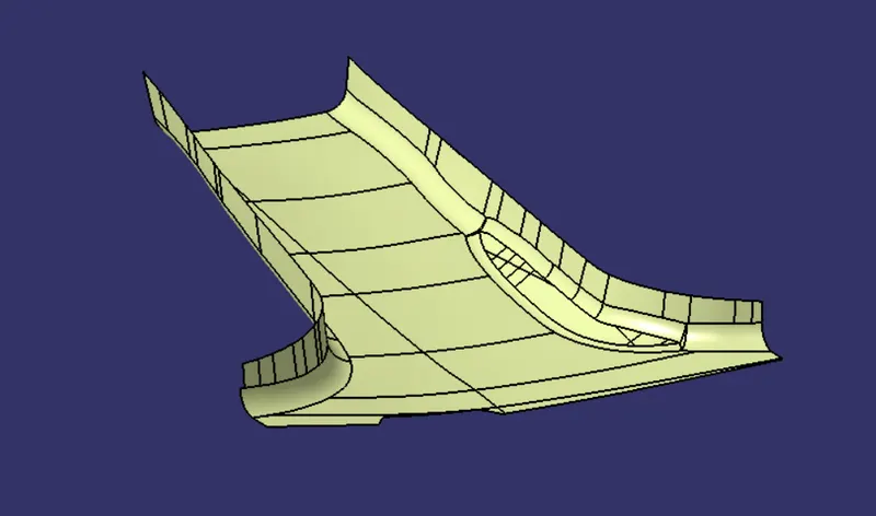
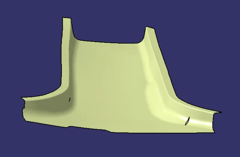
Class A of a B pillar
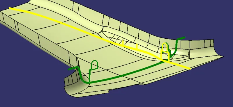
Master Sections:
PROCEDURE:
The styling surface is checked for its surface conditions.Since it is fine the tooling direction creation is commenced.
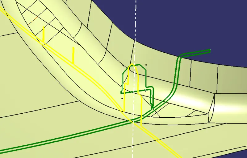
Here as the master sections are given,there are 2 dog houses with locators on it. The engineering features should also be cleared in the main tooling,so 2 reference lines are taken from the master sections of the dog house and then using bisecting method a line is created taking those 2 lines as references.
DRAFT ANALYSIS ON CLASS A:
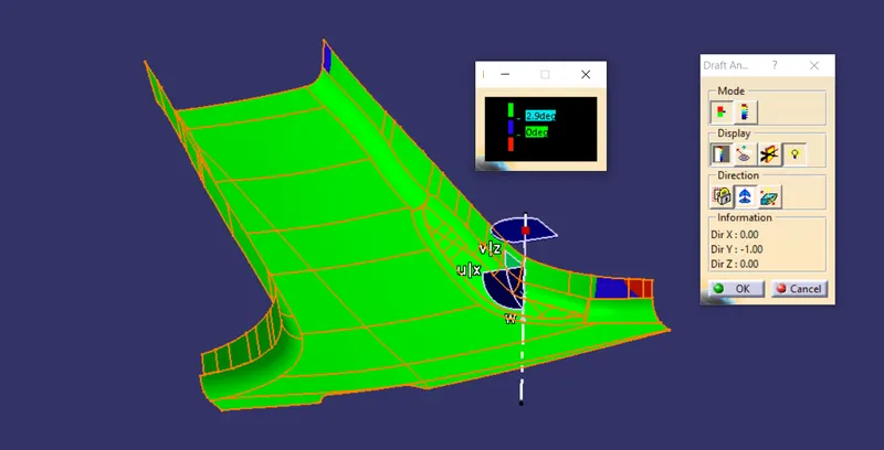
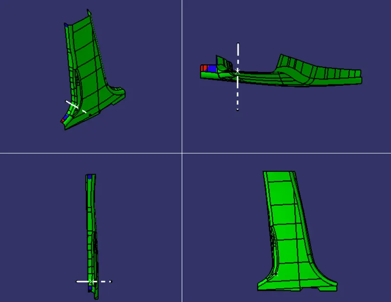
Since some areas infers to be lesser than 3 degrees. It should be either brought to the attention of the class A team or the mould engineer.
CLASS B & C SURFACE:
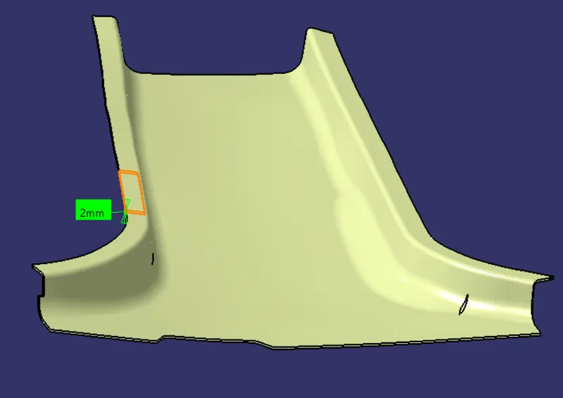
Since this A surface has stlying fillets on it,the surface is directly offsetted to 2 mm without affecting its aesthetic.
The thickness is measured using the master section.
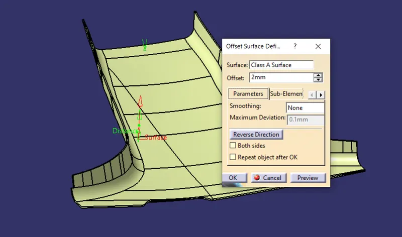
As looking into the master section it shows that it has flanges on both the sides of the B pillar.
Flange creation:
The boundary of the class A is swept using the reference surface
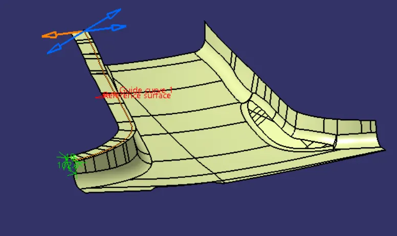
The sweep is then adjusted to match with the master section.
The same operation is done on the right side.
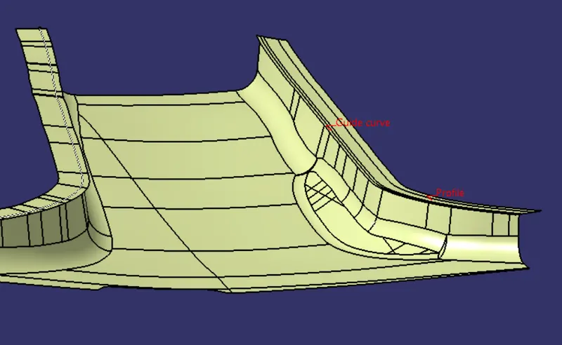
Fillet values for the flange are also taken from the master section and applied respectively.
The 2 flanges are offsetted at a distance of 2 mm and the surface is extroplated to meet the trim requirements to connect with the B surface.
C surface creation:
The C surface always follows the positive draft direction since the parting line should always fall on the B surface.
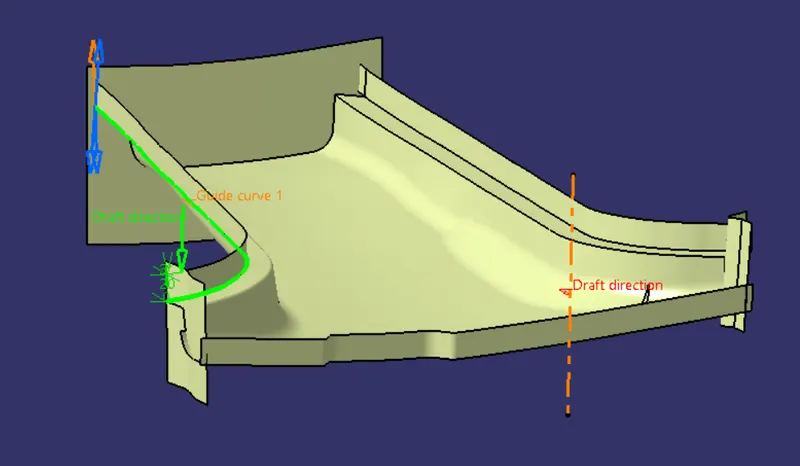
Using the sweep command the outer boundaies of the class A including the flange is swept along the tooling direction with a nominal draft of 3 degrees.
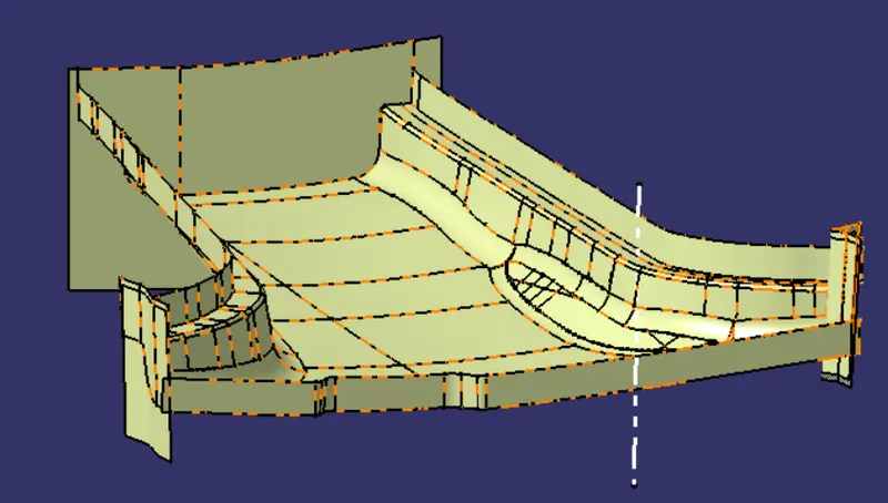
Since the C surface should follow the surface of class A, A surface is extrapolated at a minimal value to join both surfaces at some areas.
FINAL TRIM:
The B surface is extroplated a bit to trim it along with the class A & C to get the final part.
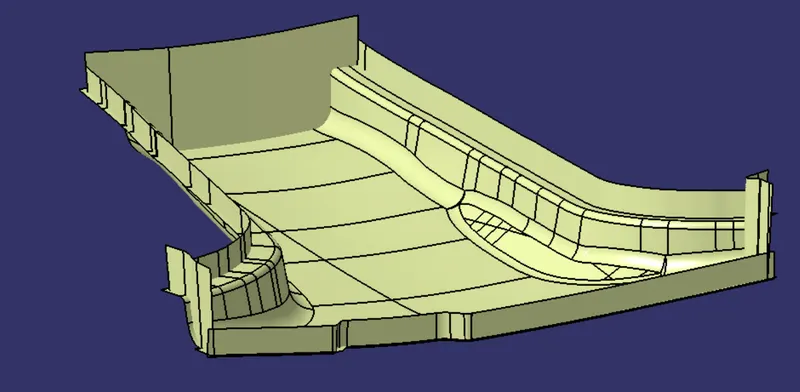
We can either do trim or do a split operation using the intersection of both the surfaces and later join them together to get the desired part.
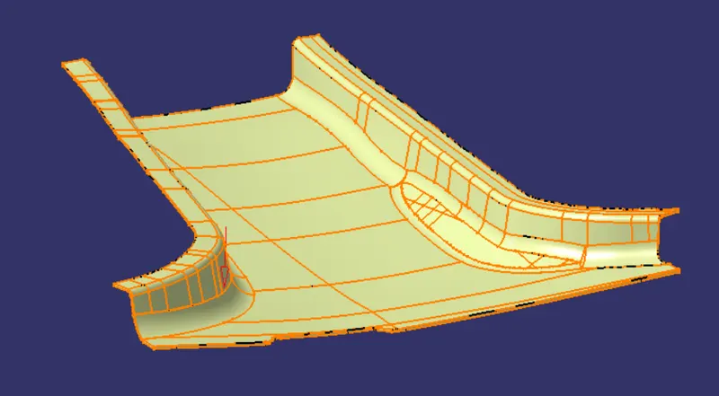
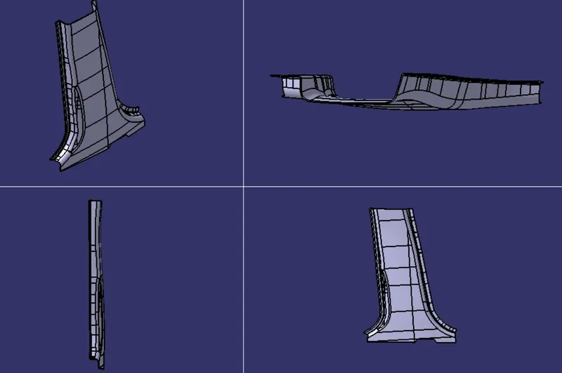
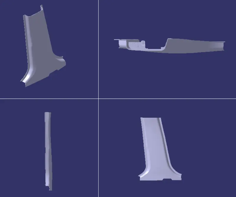
VARIOUS ORIENTATIONS:
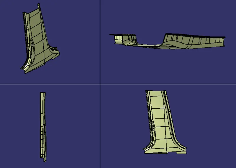
Now a solid body is created using the close surface command in part workbench.
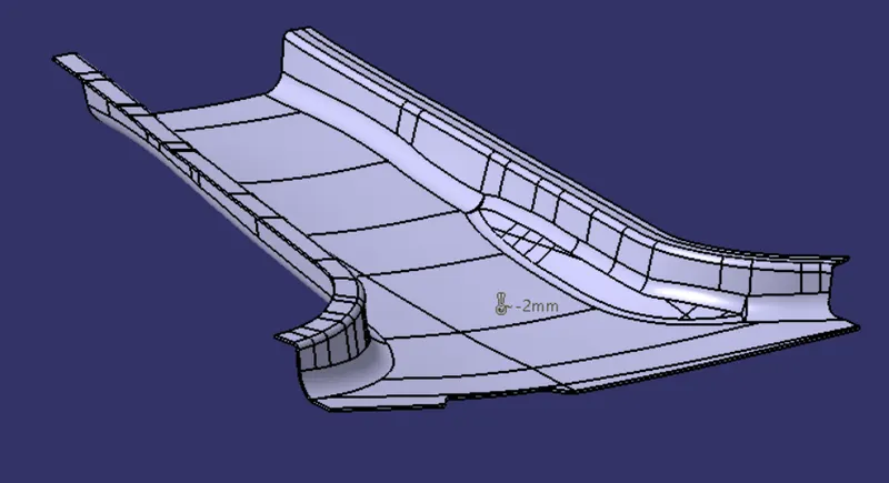
VARIOUS ORIENTATIONS:
ENGINEERING FEATURES:
By observing the master section it has 2 dog houses with a locator on it.
Reference and limits for the dog house are taken from the given master section and it is developed.
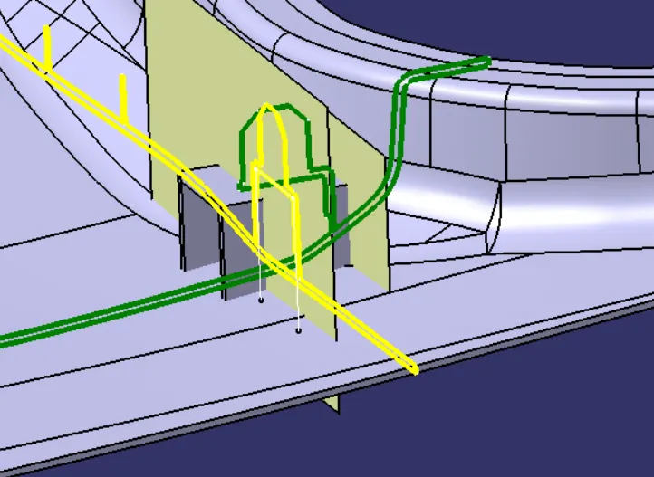
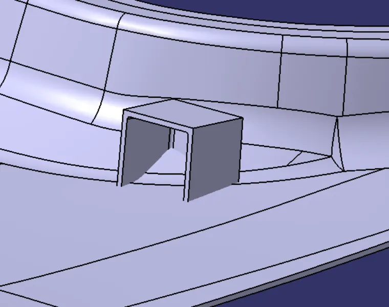
Respective drafts and edge fillets are given.
The four way locator is created by taking it limits as reference and union trimmed it along with the dog house.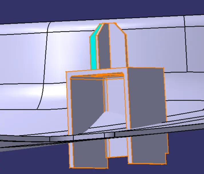
In order to avoid sink marks in class A the dog hosue design rule is implied.
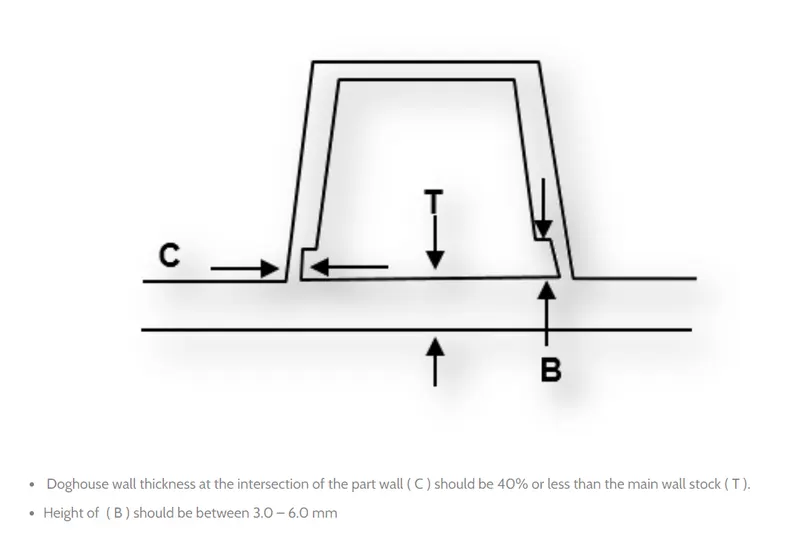
The C area thickness must be 0.8mm so the trimmed surface is offsetted to 1.2 as the dog hosue thickness is 2mm.
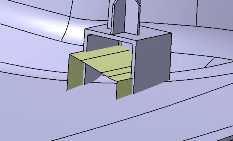
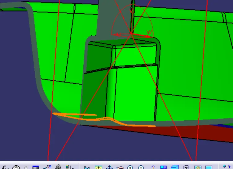
The dog house needs a separate lifter. So a lifter axis is defined along the plane where the dog house got extruded.
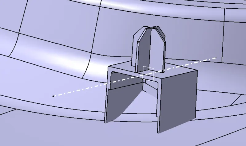
Now having the lifter axis as reference draft and fillets are given duly.
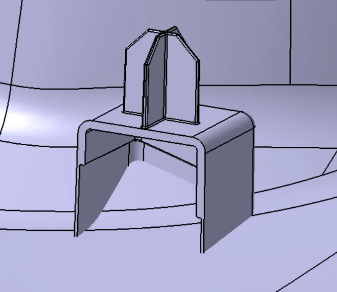
Now taking the points of both the dog houses as reference a mid point is created and a yz plane is created on it.
Now the engineering feature is mirrored using that plane.
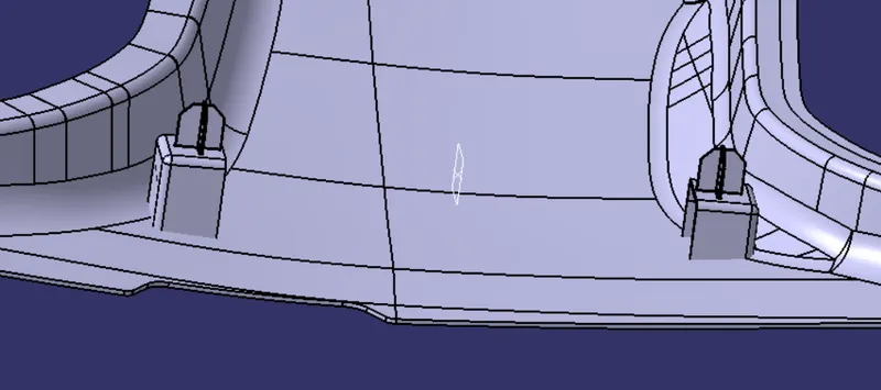
Both the dog houses are then attached to the main body.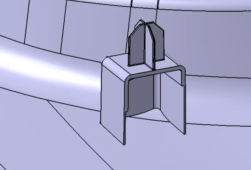
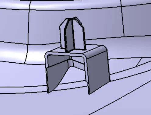
SECTION VIEW W.R.T MASTER SECTION:
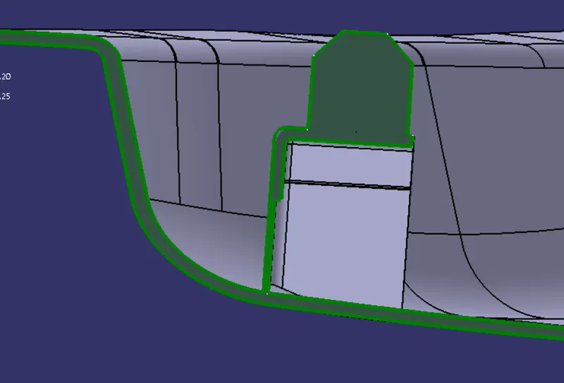
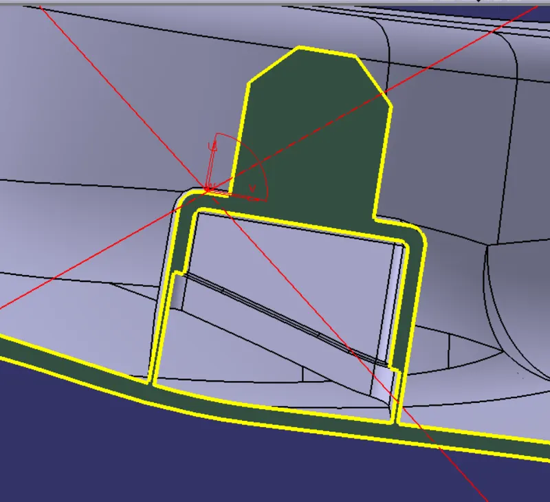
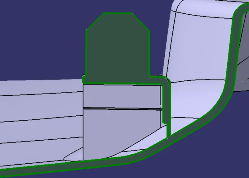
The solid body perfectly matches with the master section.
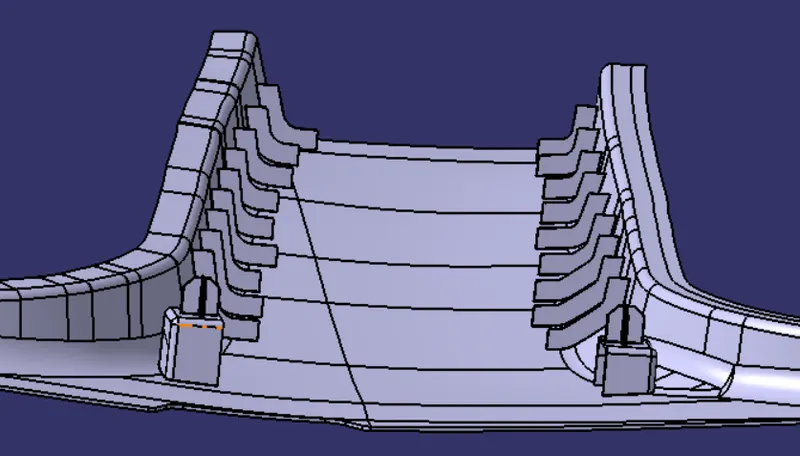
Rib:
Ribs are also supporting feature which gives additional strength to the component.
Ribs are created at a minimum distance of 50mm between them.
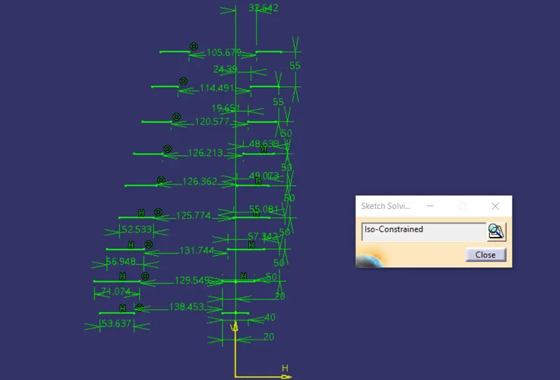
It is thickened,padded and drafted following the plastic design rules.
Thickness - 40 % of the main wall thickness
Draft - 0.5 min
Height of the rib must be 5 times the main body thickness. So the base(class B)surface is offsetted to 10mm to split the rib.
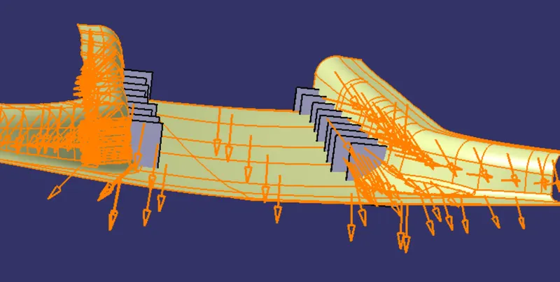
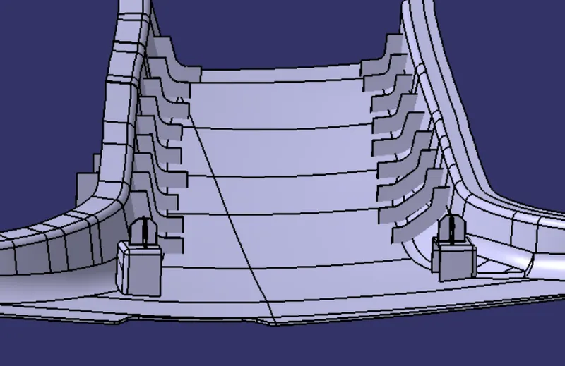
Then the ribs are added to the main body and fillets are given.
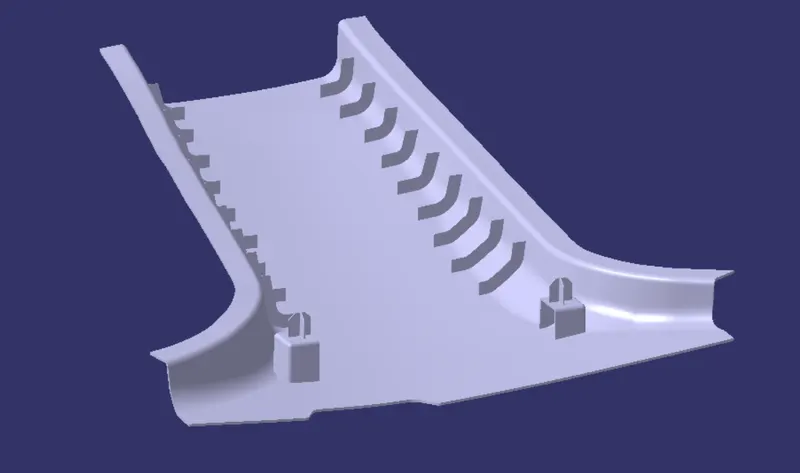
FINAL OUTPUT:
VARIOUS ORIENTATIONS:
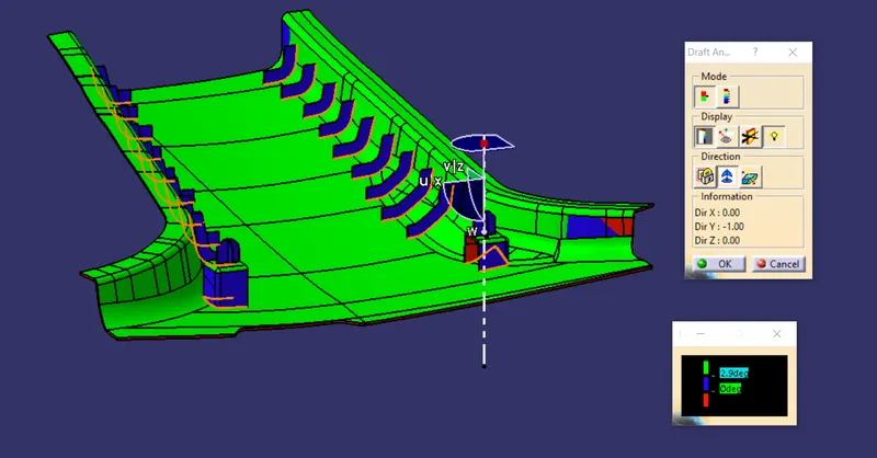
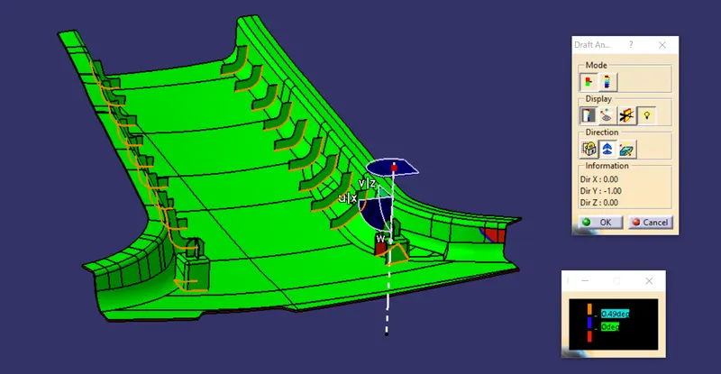
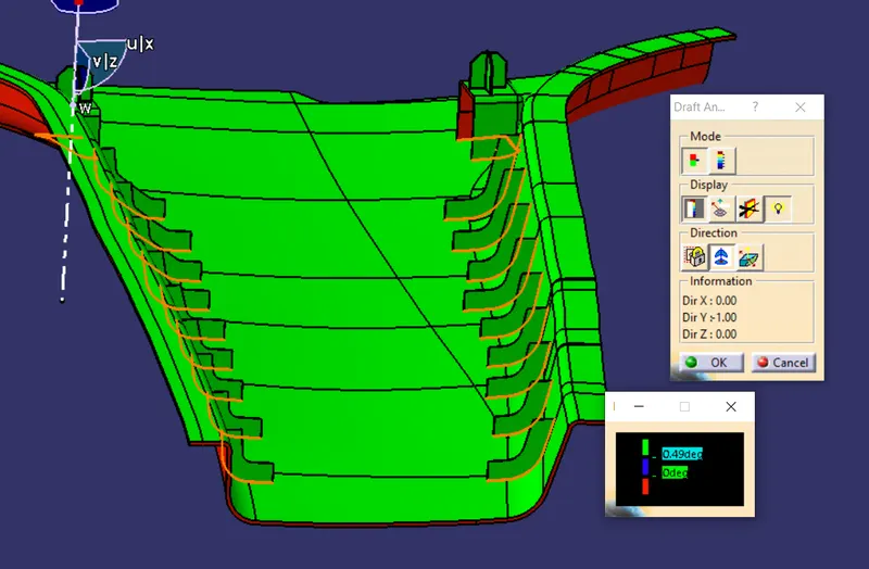
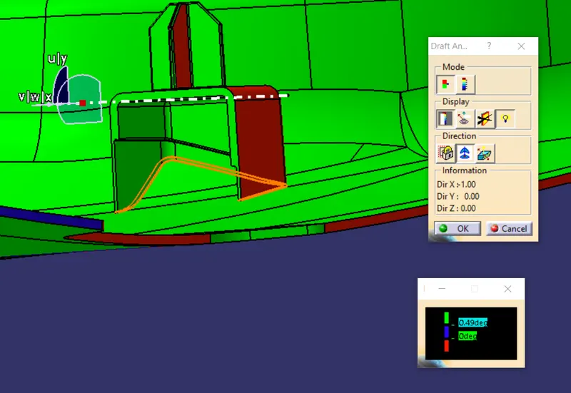
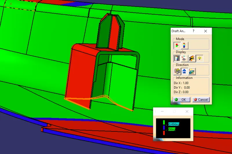
DRAFT ANALYSIS ON THE FINAL BODY:
MAIN TOOLING ON 2.9 DEG:
MAIN TOOLING ON 0.49 DEG:
LIFTER AXIS ON 0.49 DEG:
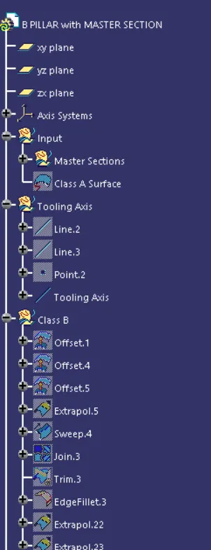
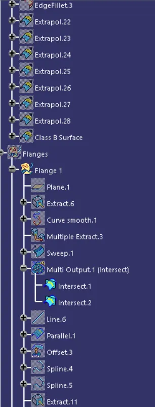
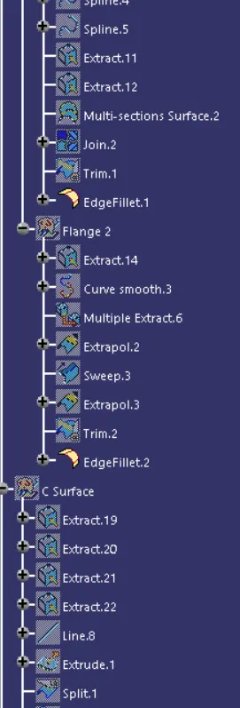
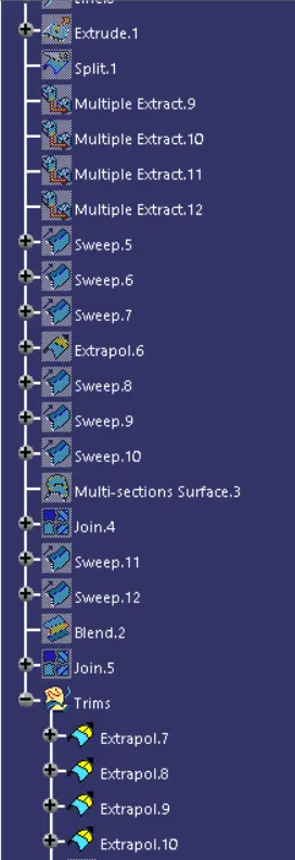
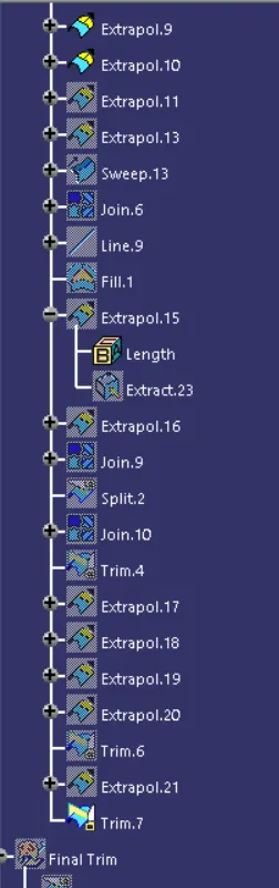
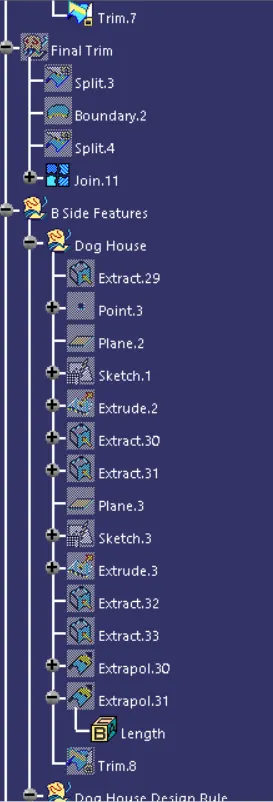
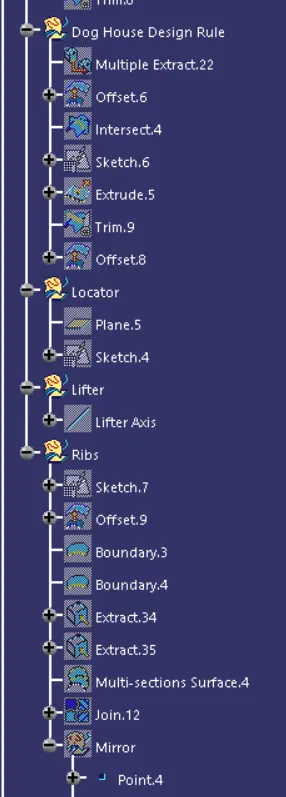
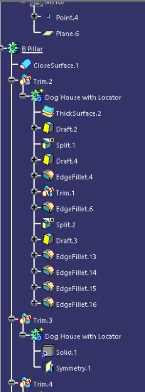
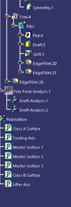
TREE STRUCTURE:
CONCLUSION:
To conclude the B pillar with all the supporting features are created following the design rules.
Software used: CATIA