Week 9 - Project - Master Section Development
AIM: Developing Master Section on Car's Central Pillar with Engineering Features.
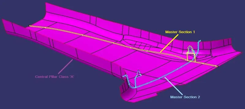
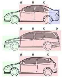
THEORY: Pillars are the vertical or nearly vertical supports of a car's window area designated respectively as the A, B, C, or (in larger cars) D-pillar, moving from front to rear, in profile view. This pillar provides structural support for the vehicle's roof panel and is designed for latching the front door and mounting the hinges for the rear doors.
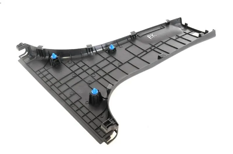
APPROACH TO WORK ON PROJECT :
- Creating Tooling Axis.
- Creating Class B Surface.
- Creating Class C Surface.
- Creating a Doghouse.
- Creating Undercut inside Doghouse.
- Creating a 4-way Locator.
- Creating Ribs on the Central Pillar.
- Performing Feature Draft Analysis.
PROCEDURE FOR CREATING TOOLING AXIS :
Tooling Axis: The tooling axis is the direction in which mold or core and cavity are opened.
We have to check all possible tooling directions in all three axes. When we are deciding the tooling axis we have to make sure that all the faces should be visible to that tooling axis, no face should be hidden.
STEP 1: Ensure there is no gap between the two neighboring surfaces.
Operations>Boundary>definition>select component
STEP 2: Enable Master Section 1 and extract two separate lines from it as shown below -
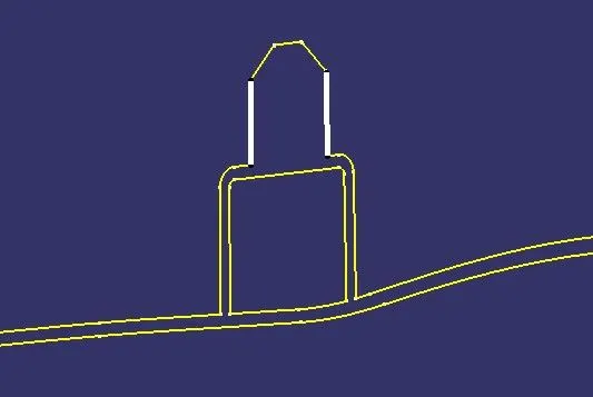
STEP 3: Add the Middle point between these two extracted lines from the point definition.
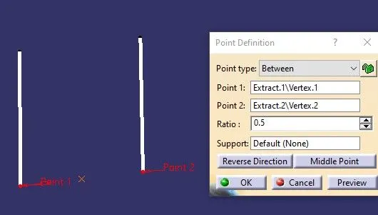
- As we can see that for this particular model the master section 2 of Assembly of Doghouse and four-way locator is not extracted properly.
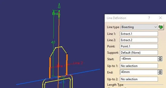
- So, We’ll extract the line from the point we created and make it a Tooling Axis.
NOTE: If master section 2 had proper lines then we can also follow the extension of two lines from them and then the result of all four bisected lines can be taken as the tooling axis.
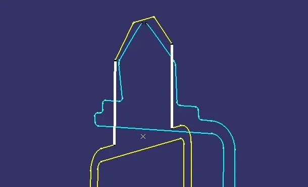
STEP 4 : Extract the line from the point and make it a Tooling Axis.
STEP 5 : Rename, change color and give thickness to the tooling axis so that it can be easily identified.
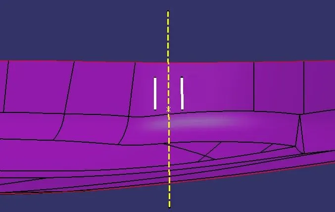
STEP 6: Publish Tooling Axis
Select tooling axis in model tree>Toolbar>tools>publication>ok
PROCEDURE FOR CREATING B SURFACE :
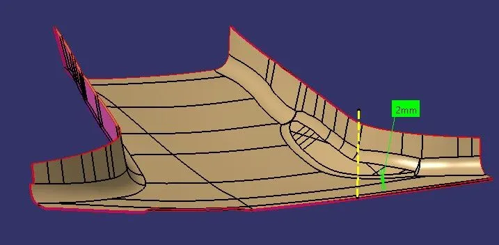
STEP 1: Offset the Class A surface to 2mm as shown in the figure below-
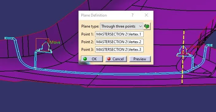
STEP 2: Create a Plane using three points in master section 2.
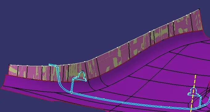
STEP 3: Tangentially extract the boundary and Multiple extracts from one side of the A surface as shown-
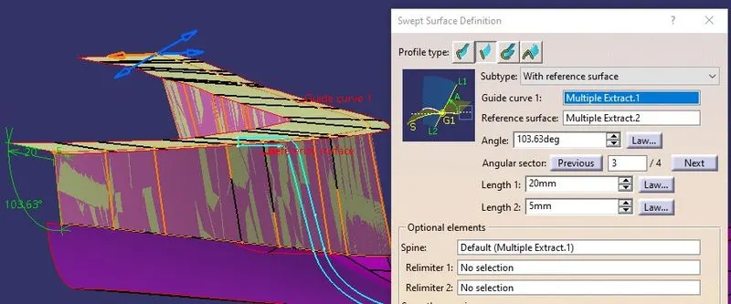
STEP 4: Sweep the extracted boundary with the reference surface as shown.
STEP 5: Intersect Class A, Sweep with Created Plane 1.
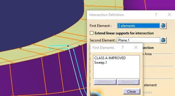
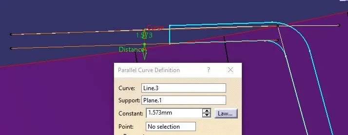
STEP 6:
- Create a Parallel line from the intersection of sweep until the distance till it overlaps with master section 2.
- Measure the distance and angle between the parallel line and master section 2, the distance should be very less and the angle should be near to zero degrees.
- The deflected angle value between these can be added to sweep definition degrees which will make a more accurate sweep with A surface and will Match with master section 2.
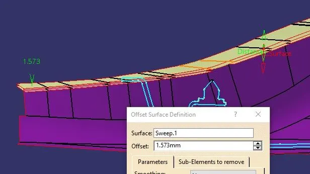
STEP 7: Offset the sweep below the distance equal to parallel distance so that sweep offset will overlap with master section 2 from the below portion.
STEP 8: Now again offset the flange to 2mm above direction so that it will overlap with master section 2 from the above portion.
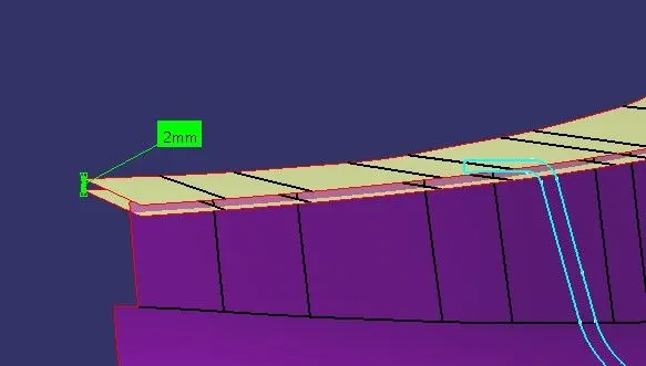
- We can see the distance and angle between sweep and master section 2 is as low as possible we made it to do.
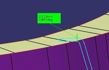
STEP 9: Tangentially extract the boundary and Multiple extracts from one side of the A surface as shown-
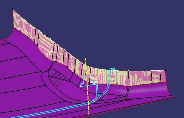
STEP 10: Sweep the extracted boundary with the reference surface as shown.
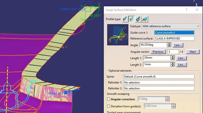
STEP 11: Intersect Class A, Sweep 2 with Created Plane 1.
- Extract a line from Intersection of Sweep 2.
- Extract a line from below the master section 2 flange.
- Measure the distance and angle between these two lines, the distance should be very less and the angle should be near to zero degrees.
- The deflected angle value between this can be added to sweep 2 definition degrees which will make a more accurate sweep with A surface and will Match with master section 2.
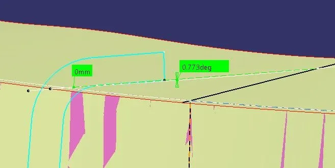
STEP 12: Offset the second flange sweep to 2mm above direction so that it will overlap with master section 2 from the above portion as well.
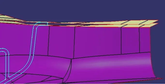
NOTE: We Can see that the Class ‘A’ surface is not intersecting below the sweep flange surface, so we need to extrapolate the Class ‘A’ surface.
STEP 13: Extrapolate the Input Class ‘A’ surface to the above direction with a few millimeters until it intersects with flanges
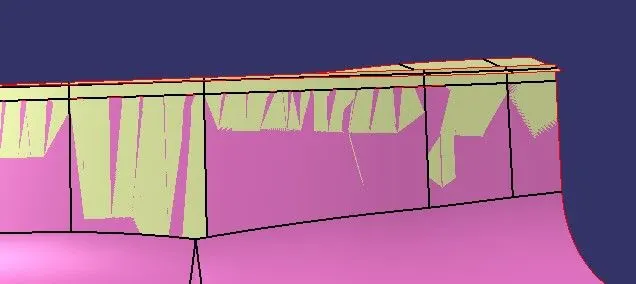
STEP 14: Trim the Class A surface with Both sides of the below Flanges.
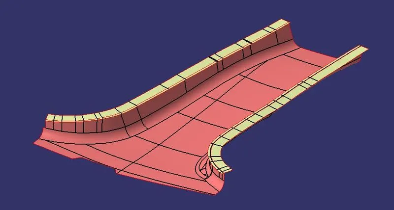
STEP 15: Also Trim the Class A’s 2mm offset surface with Both sides of the above Flanges, which will say to be Class ‘B’ Surface as shown below-
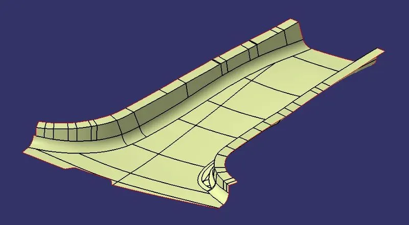
- We can observe that Both the surfaces are also overlapping with master section 2, which fulfills our purpose.
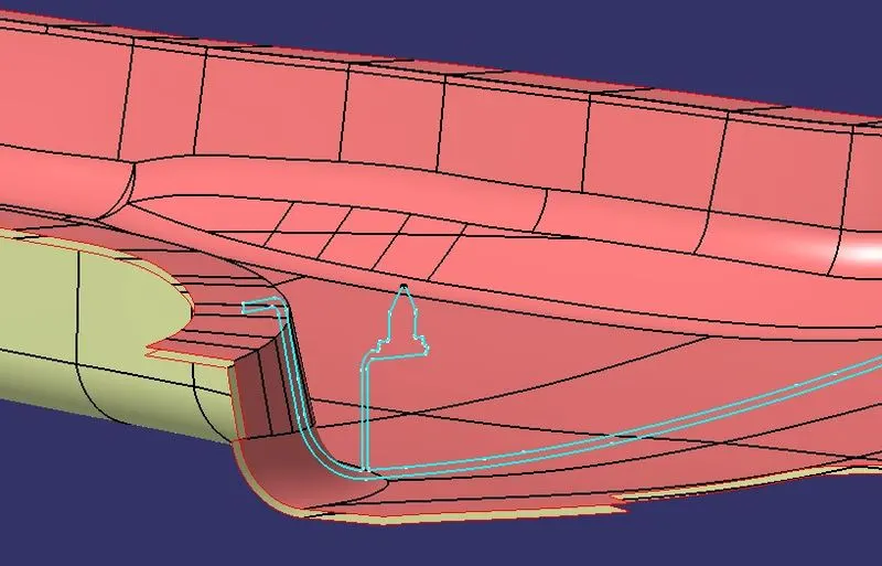
NOTE: Blow Surface will now be considered as an updated Class ‘A’ Surface.
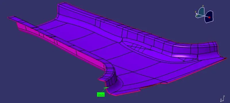
STEP 16: Adding Fillet to ‘A’ and ‘B’ class surfaces at edges of both flanges.
- Add Edge Fillet radius of 2.5mm to Class A surface.
- Add Edge Fillet radius of 2.5mm+2mm thickness = 4.5mm to Class B surface.
PROCEDURE FOR CREATING C SURFACE :
STEP 1: Extracting Sweeps from boundary Class A surface as shown.
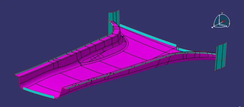
STEP 2: Extrapolating all the sweeps so that they intersect with each other to trim.
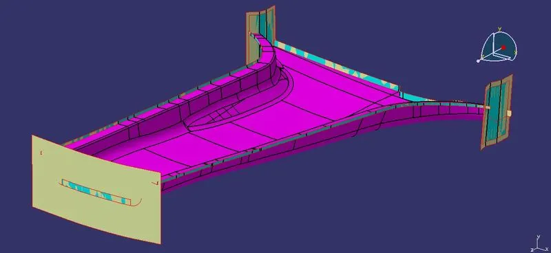
NOTE: We can see that still Class ‘A’ surface is not intersecting with all the sweeps, so we need to extrapolate the class ‘A’ surface for a few millimeters.
STEP 3: Trim all the Sweeps to get all joining of sweeps.
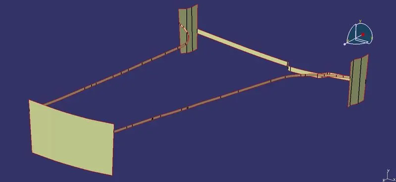
STEP 4: Extrapolate the class ‘A’ surface for a few millimeters so that it intersects with all sweep as shown below-
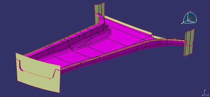
STEP 5: Trim both surfaces.
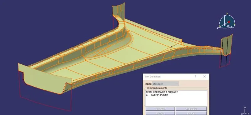
- We can see the trimmed surface below, called Class ‘C’ surface.
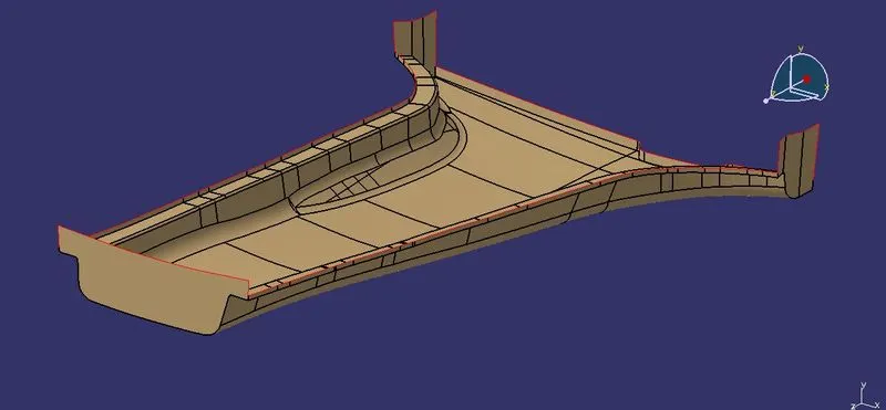
STEP 6: Unhide the ‘B’ Surface
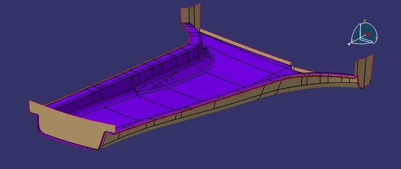
STEP 7: Trim Class ‘B’ with Class ‘C’ surfaces.
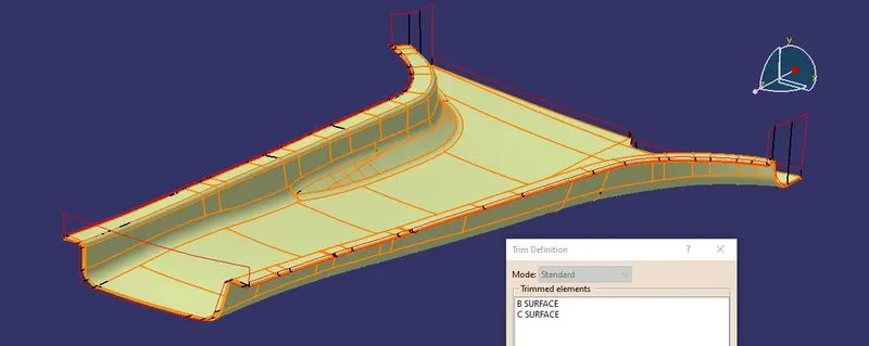
- We can see the final trimmed surface as below -
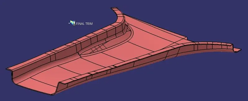
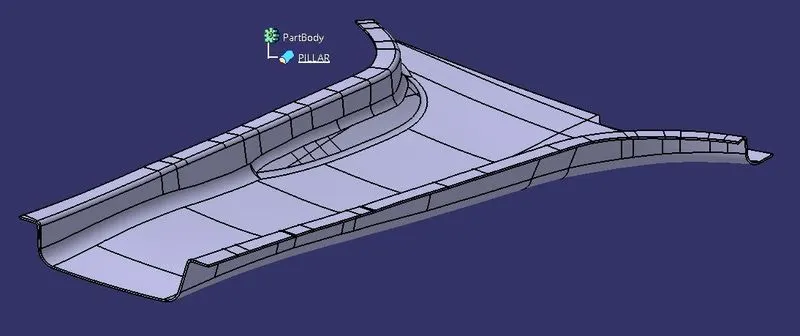
STEP 8: Switch to Part Design Workbench, Define Part body to make it a solid component by closing surface panel.
PROCEDURE FOR CREATING DOGHOUSE :
STEP 1: Extract a line from the Master Section 1 as shown below-
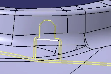
STEP 2: Create a middle point on that line.
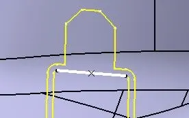
STEP 3: Create a plane on the point, parallel to master section 1.
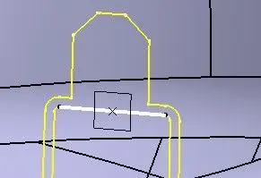
STEP 4: Draw a sketch.
- Use Project 3D element to extract lines from master section 1.
- Trim and extend lines as shown below.
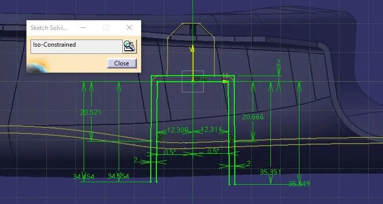
- A sketch can be shown as below :
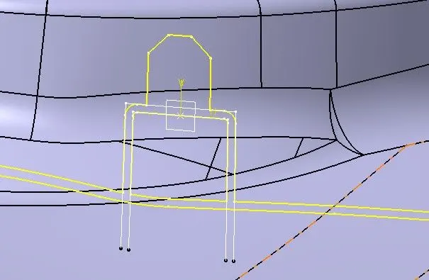
STEP 5: Extract the below set of lines.
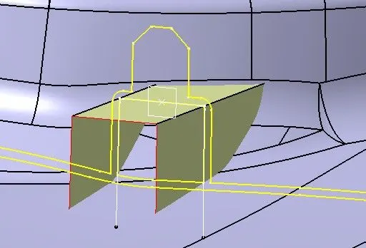
STEP 6: Create a plane on the same point, perpendicular to master section 1.
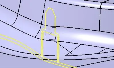
STEP 7: Draw a sketch.
- Copy and paste the earlier sketch.
- Change the sketch support to the new plane we created.
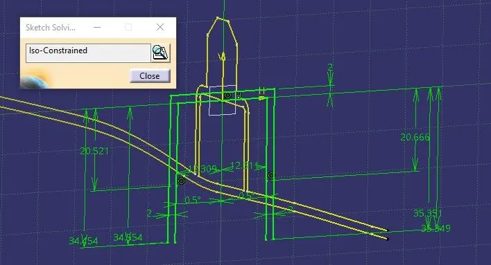
- Sketch can be shown as below :
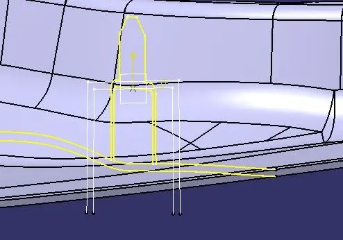
STEP 8: Extract two lines from the sketch and Extrude it as shown below.
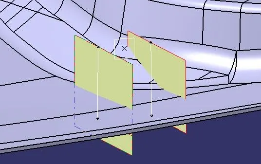
STEP 9: Extrude the surface for the doghouse.
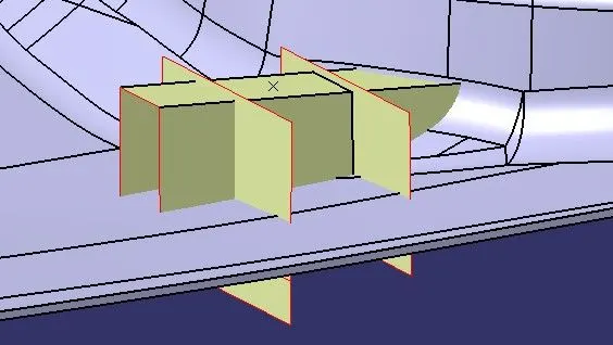
STEP 10: Trim the surface with right-side extruded surfaces.
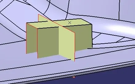
STEP 11: Switch to Part Design Workbench, Thicken the surface by 2 mm as shown below-
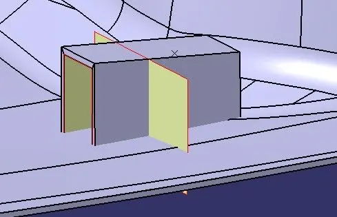
STEP 12: Split the solid with left side extruded surface as shown below-
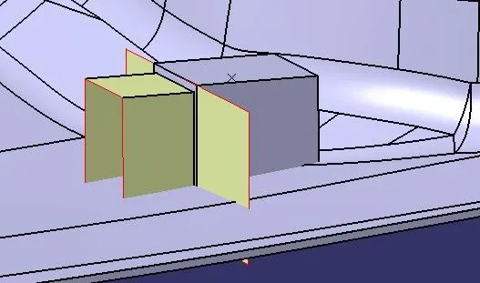
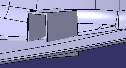
- Thicken part of the dog house can be seen as below-
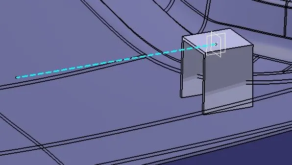
STEP 13: Extract a line from the point perpendicular to dog house as Lifter Axis-
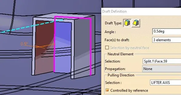
STEP 14: Draft the inside surfaces of the Dog House with 0.5 degrees of draft angle.
PROCEDURE FOR CREATING UNDERCUT INSIDE DOGHOUSE :
STEP 1: Unhide the earlier extruded surfaces and trim both the surfaces
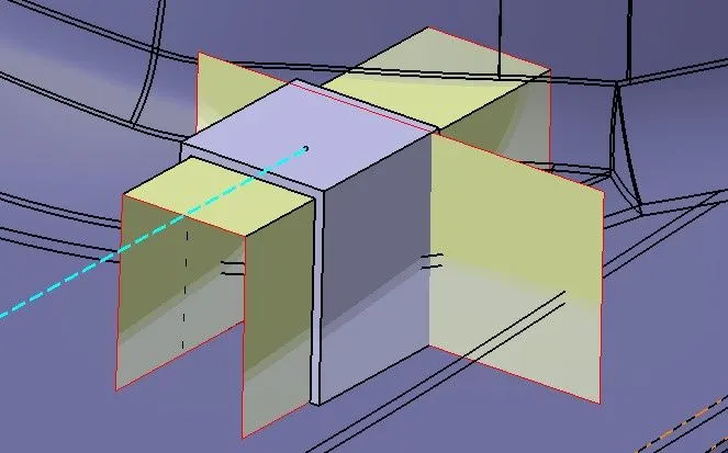
- Trimmed surfaces can be shown as below -
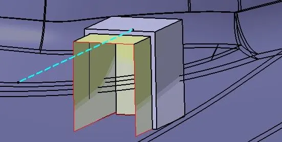
STEP 2: Split the surfaces
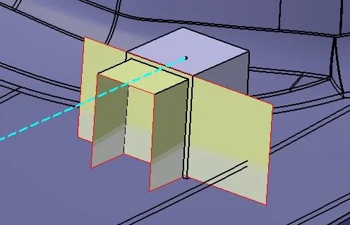
- Split surfaces can be shown as below -
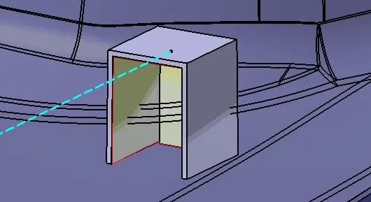
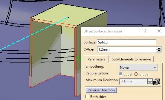
STEP 3: Offset the surface to 1.2 mm.
NOTE: Offset distance is decided by 40% of the thickness.
- 40⋅(1100)⋅2mm=0.840⋅(1100)⋅2mm=0.8
- 2mm−0.8mm=1.2mm2mm-0.8mm=1.2mm
STEP 4: Extract the line from sketch 1 parallel to the dog house.
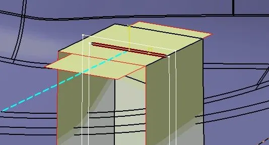
STEP 5: Extrapolate the surface and offset it downwards with a few millimeters.
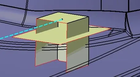
STEP 6: Trim the surface as shown below-
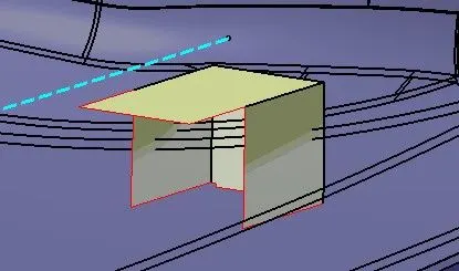
STEP 7: Switch to Part Design Workbench and split the solid towards the solid surface.
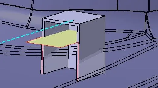
- Undercut solid can be shown as below-
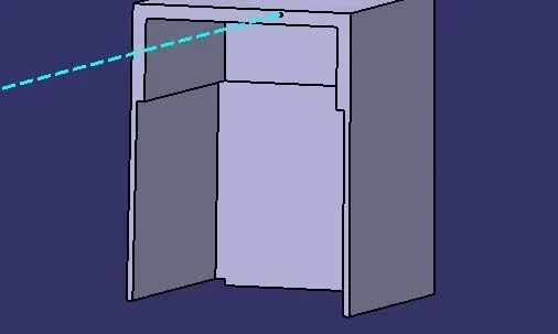
STEP 8: Draft the inside surfaces of the Undercut Dog House with 0.5 degrees of draft angle.
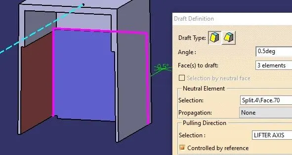
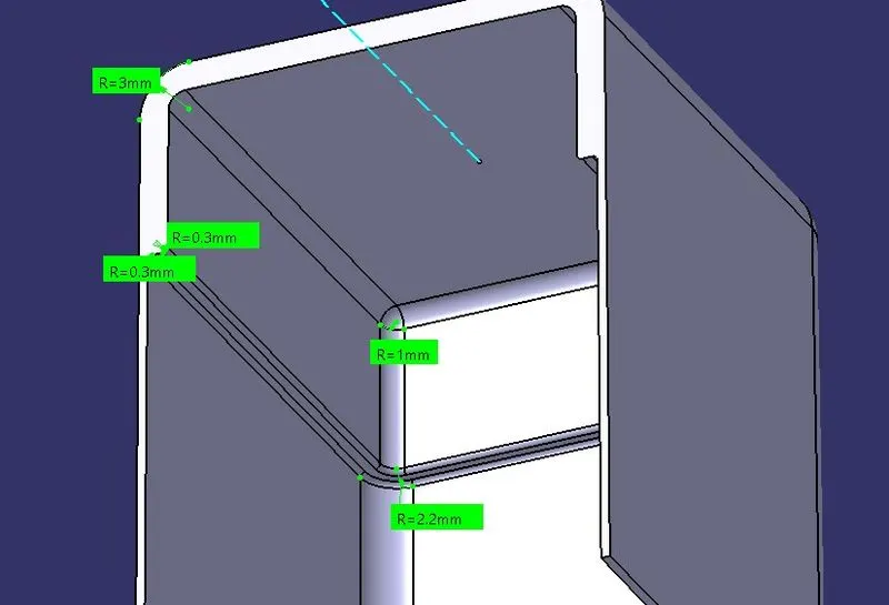
STEP 9: Give the Edge Fillet on doghouse with the following Radius as shown below-
PROCEDURE FOR CREATING 4 WAY LOCATOR :
STEP 1: Create a Plane Perpendicular to master section 1 on the earlier point as shown.
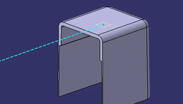
STEP 2: Draw a sketch
- Use Project 3D element to extract lines from master section 1 to set a limit for width of four-way locator vertically.
- Draw a line horizontally of equal length.
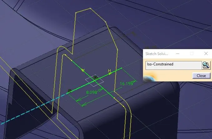
- Sketch can be shown as below :
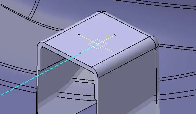
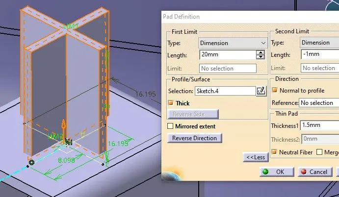
STEP 3: Pad the sketch with 1.5 mm thickness and following parameters.
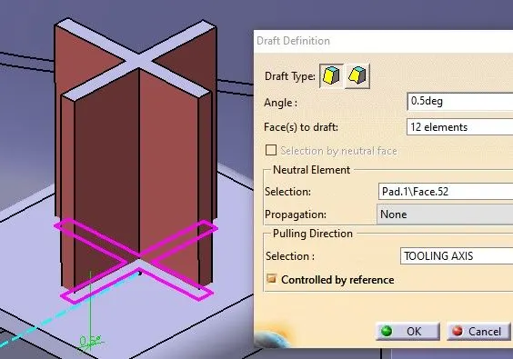
STEP 4: Draft all the faces of the 4 way locator with 0.5 degrees and other parameters shown below.
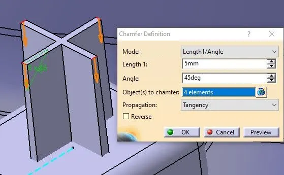
STEP 5: Give a Chamfer of 5mm with 45 degrees.
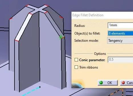
STEP 6: Give an edge fillet of 1mm on the chamfer area.
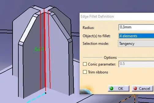
STEP 7: Give an edge fillet of 0.3mm on all the faces of the 4-way locator.
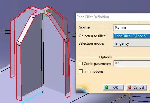
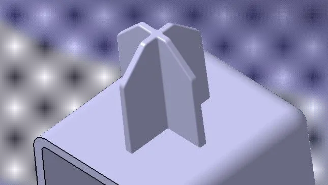
We can see a 4-way locator after all operations as below -
STEP 8: Assemble the 4 Way Locator Inside Doghouse.
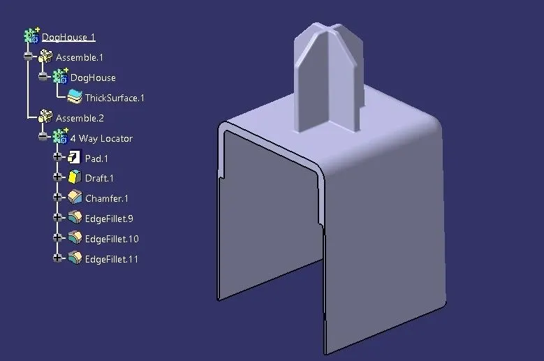
STEP 9: Union Trim the Assembly of 4 Way Locator and Doghouse in Pillar Part Body.
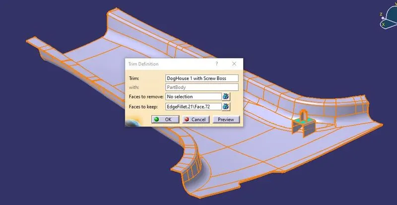
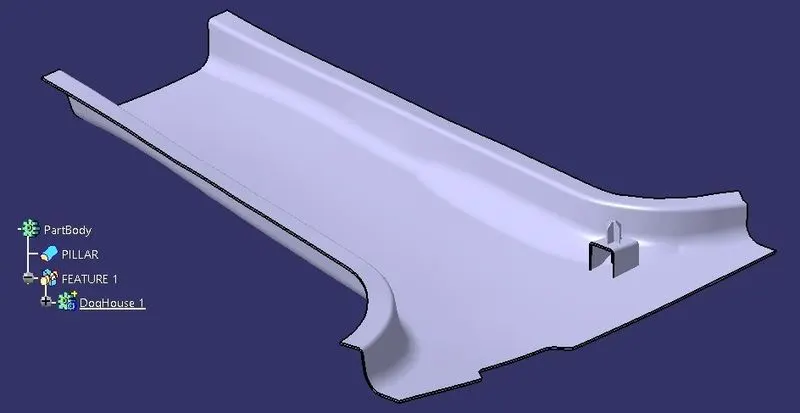
STEP 10: For Creating Duplicate of the Assembly of the doghouse and 4-way locator.
- Create a new point with the help of master section 2 as shown below-
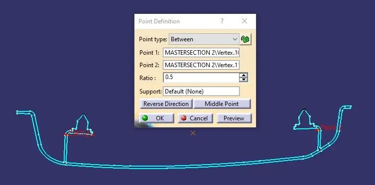
STEP 11: Create a Plane Perpendicular to master section 2 on that point.
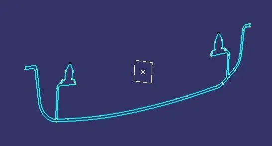
STEP 12: For Creating Duplicate of the Assembly of doghouse and 4 way locator.
- Copy the Assembly and paste special in the main model tree.
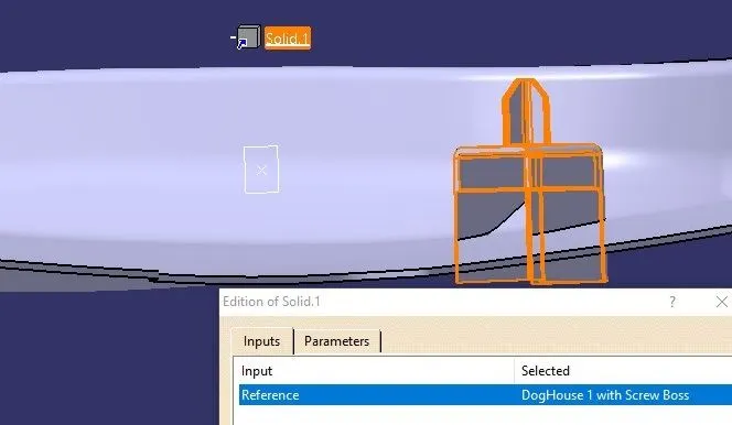
STEP 13: Select the Duplicate solid and select the plane to get symmetry as shown below.
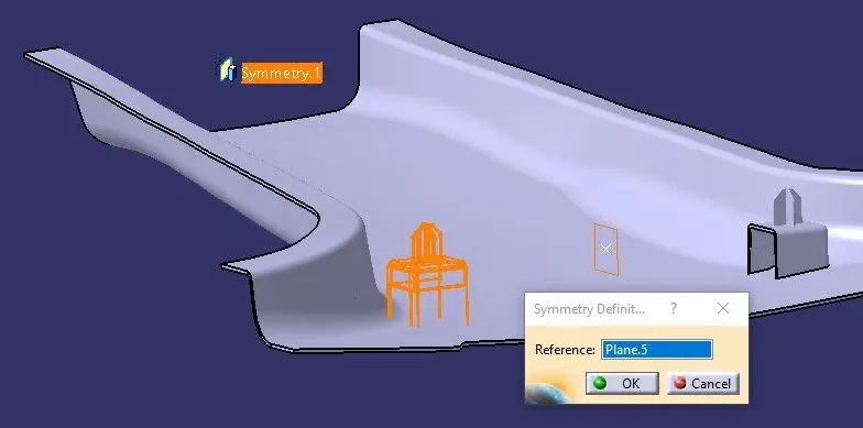
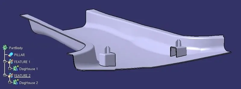
STEP 14: Union Trim the Assembly of second 4 Way Locator and Doghouse in Pillar Part Body.
PROCEDURE FOR CREATING RIBS IN PILLAR :
STEP 1: Draw a sketch of ribs with 50mm distance between each rib, as shown below-
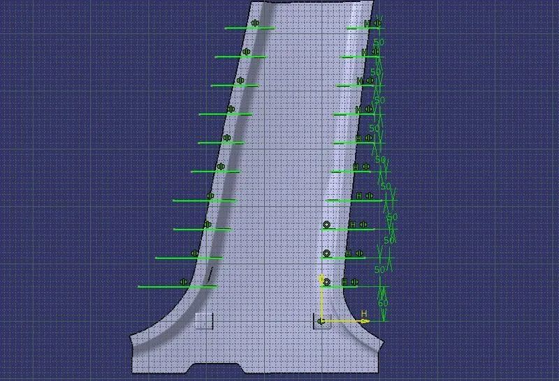
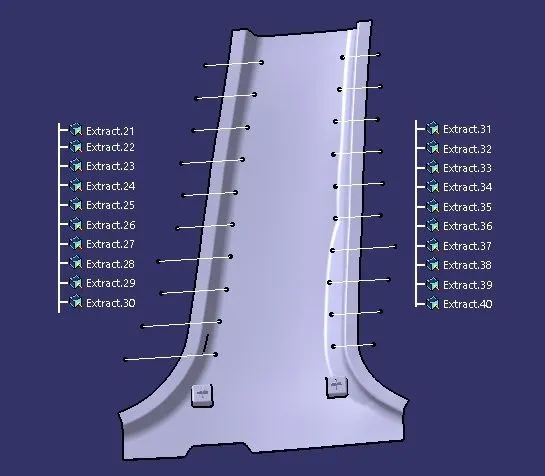
STEP 2: Extract the individual lines from the sketch as shown below-
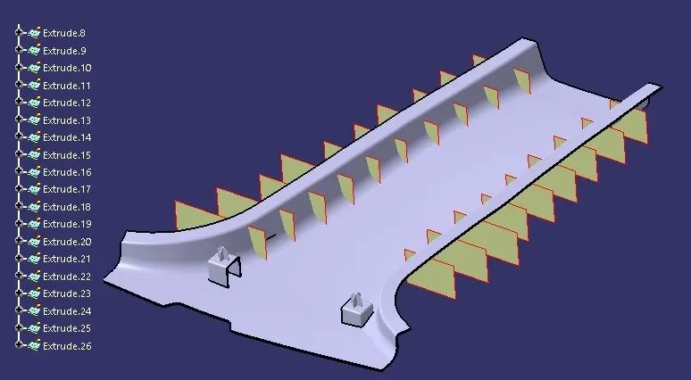
STEP 3: Extrude the individual lines to the surface perpendicular to the pillar.
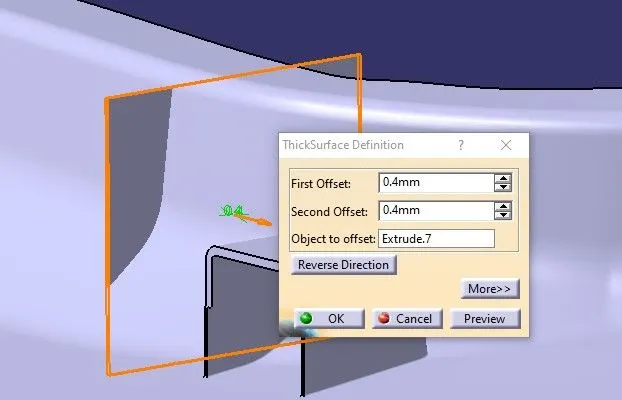
STEP 4 : Thicken the individual ribs.
NOTE : Thickness of ribs = 40 % of part thickness = 40⋅(1100)⋅2mm=0.8mm40⋅(1100)⋅2mm=0.8mm
- We’ll give 0.4mm+0.4mm from each side of the thickened surface definition.
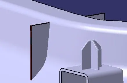
- Thicken Rib can be shown as below-
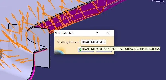
STEP 5: Split the thickened rib with Improved Class ‘A’ Surface toward the pillar.
STEP 6: Height of the Rib
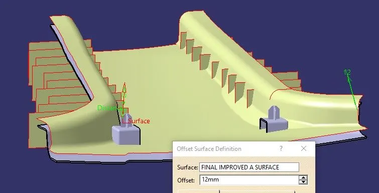
NOTE : Height of the Rib = 5 times the thickness = 5⋅2mm=10mm5⋅2mm=10mm
- Offset the Improved Class ‘A’ Surface to 12mm (10mm from Class ‘B’ Surface).
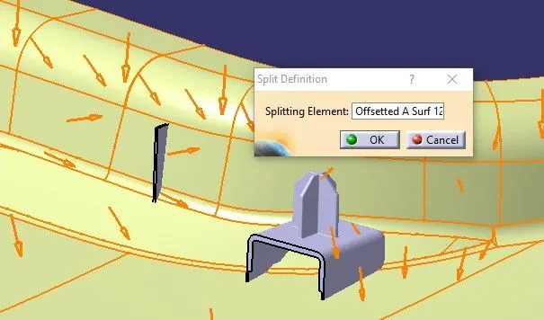
STEP 7: Split the thickened rib with offset Improved Class ‘A’ Surface toward the pillar.
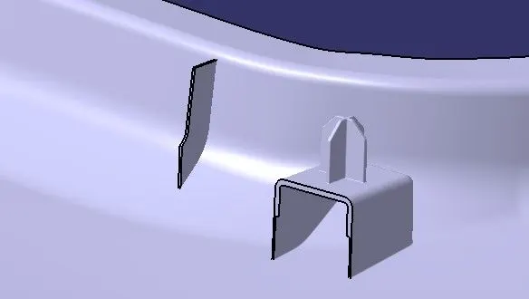
- We’ll get the following out of RIb.
STEP 8: Draft the surfaces of the Rib with 0.5 degrees of draft angle and the following parameters.
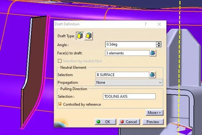
- Drafted Rib Can be Shown as below-
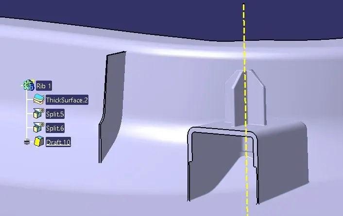
STEP 9: Repeat Step 4 to Step 8 to obtain all the ribs and assemble it to a single body.
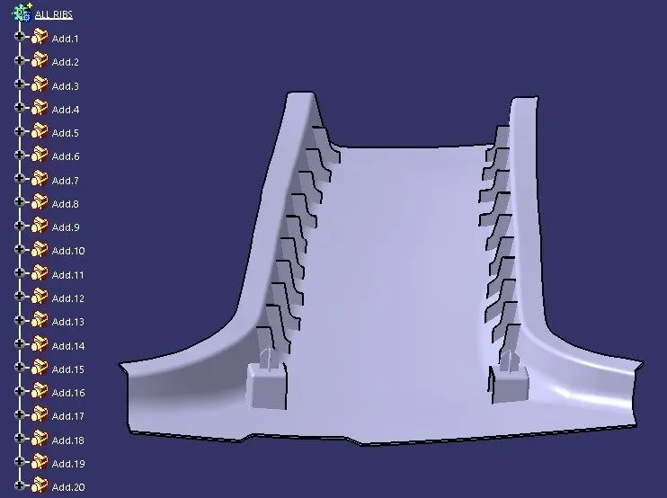
STEP 10 : Union Trim the Body of Ribs in Pillar Part Body.
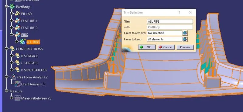
RESULTS :
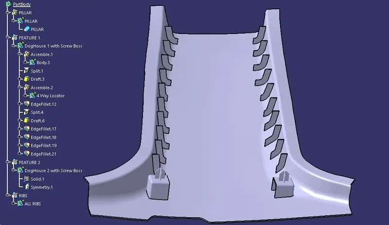
- Part Body Tree
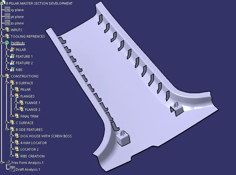
- Final Model Tree
PROCEDURE TO CHECK DRAFT ANALYSIS :
STEP 1: Changing view mode to the material.
View mode>view mode customisation>tick material>ok
STEP 2: Calling Draft Analysis.
Toolbar>Insert>Analysis>Feature Draft Analysis
STEP 3:
- Drag the compass from the draft analysis box on the tooling axis and place it properly.
- Click on locks so the compass will get locked to the tooling axis.
- Click anywhere on the component.
- Click OK.
- Analysis of the color of the failing and passing surfaces.
If a component is showing in a Green color that means our component is ready for manufacture.
NOTE: If we find zero degree or negative degree failing color, we can fix it by changing the draft angle, sweep direction, modifying properly tooling axis, etc.
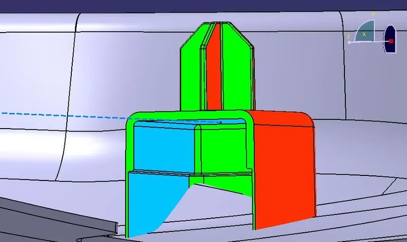
- Feature Draft Analysis on Doghouse with Lifter Axis, We can see that the inside walls are clearing.
- Feature Draft Analysis on Second Doghouse with Lifter Axis, We can see that the inside walls are clearing.
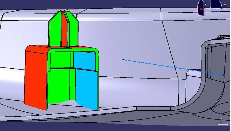
NOTE: Outside walls of the doghouse and the 4-way locator will be cleared by Main Tooling Axis.
- Feature Draft Analysis on Central Pillar.
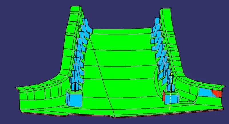
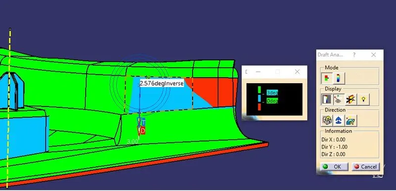
- All the Blue Colour area has a draft of 0.5 degrees and 3 degrees on other faces.
- Minimum draft of this area is 2.57 degrees.
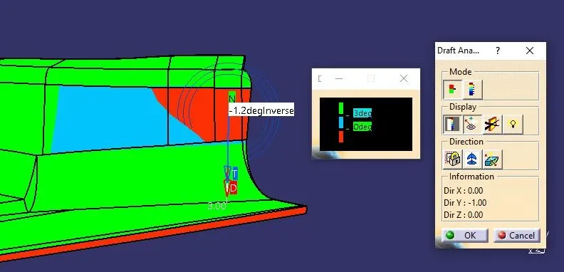
- The minimum draft of this area is -1.2 degrees.
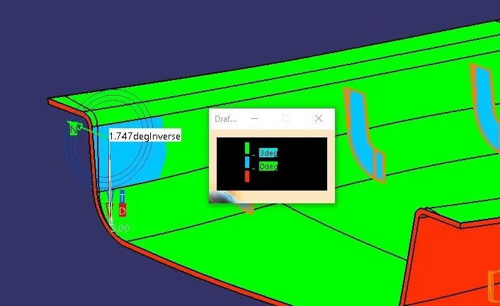
- Minimum draft of this area is 1.74 degrees.
- Feature Draft Analysis on Central Pillar ‘A’ Surface side.
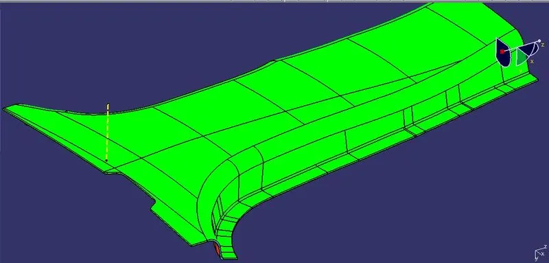
- All areas above are with a minimum draft of 2.9 degrees except they are shown below :
- Minimum draft of this area is 2.78 degrees.
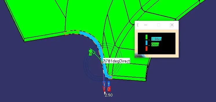
- The reason for not clearing the draft for 2.9 degrees is mentioned below.
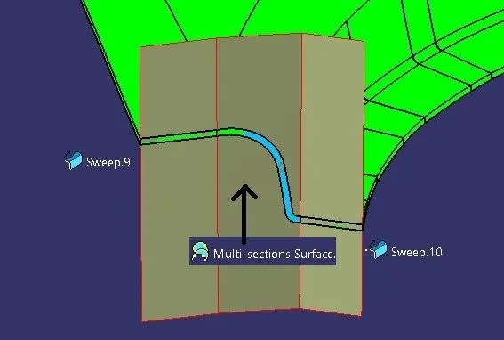
NOTE: The Sweep at the multisection area was failing due to the curvy area in Class A
- Feature Draft Analysis on Central Pillar ‘A’ Surface side.
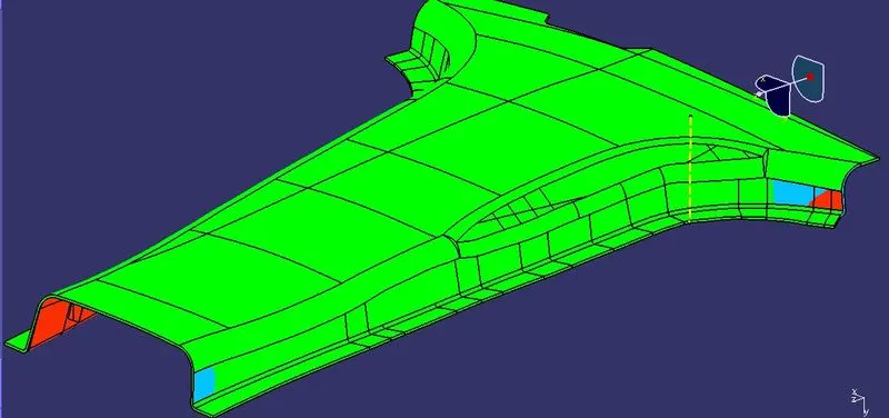
- All areas above are with a minimum draft of 2.9 degrees except they are shown below :
- Minimum draft of this area is 2.78 degrees.
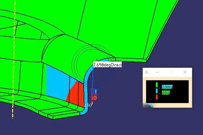
- The reason for not clearing the draft for 2.9 degrees is mentioned below.
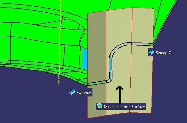
NOTE: The Sweep at the multisection area was failing due to the curvy area in Class A
CONCLUSION :
Creation of Class B, Class A surface, Doghouse, 4 Way locator, Ribs through Master Sections has been successfully done on Pillar by the guidance of design rules. The tooling axis and the Lifter axis also have been created according to the OEM standard.
LEARNINGS :
- Creating tooling axis.
- Creating a Lifter axis.
- Creating class B surfaces.
- Creating class C surfaces.
- Creating a Doghouse.
- Creating 4-way Locators.
- Creating Ribs.
- Symmetry solid part.
- Application of Master Sections and Design through it.
- Feature Draft Analysis on Doghouse, 4-way locator, and Pillar.