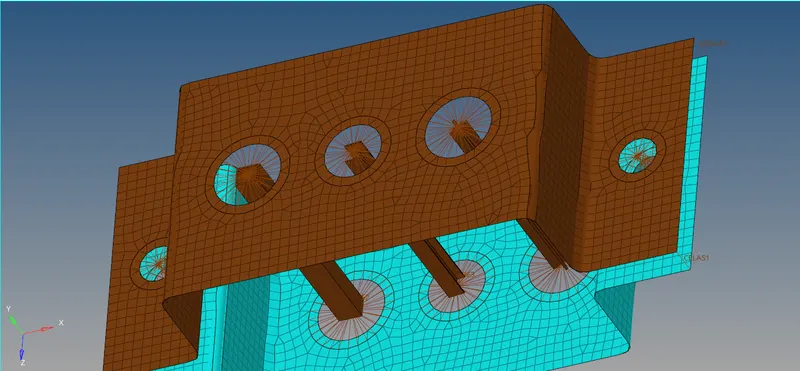
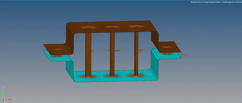
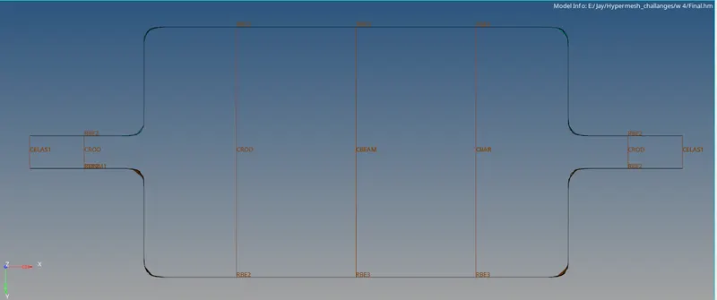
Week 4-1D Element Creation Challenge
Mesh the Given component with the Size of 5 Units. Create 1D elements on the following component with given cross-section and DOF
AIM : Mesh the Given component with the Size of 5 Units. Create 1D elements on the following component with given cross-section and DOF
PROCEDURE : Import Geometry from the downloads (File type IGES)
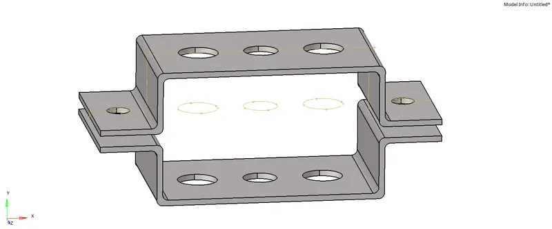
STEP 1 : Creating Midsurface
*Geom--Midsurface--Auto extraction--Select Surface.
> we can delete solid entity after all midsurface created and aslo at model .
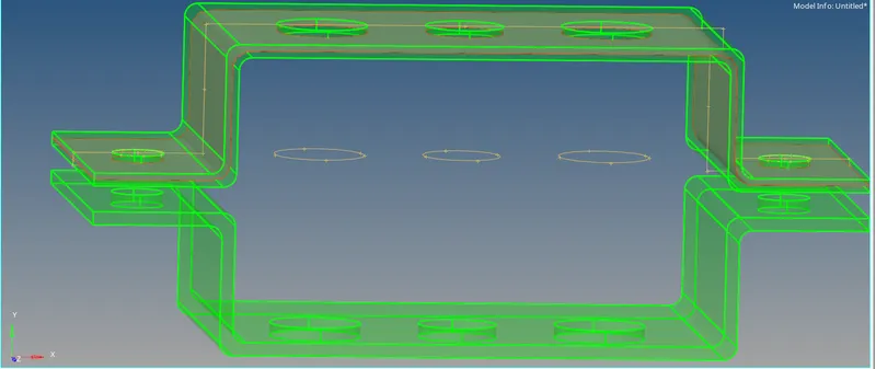
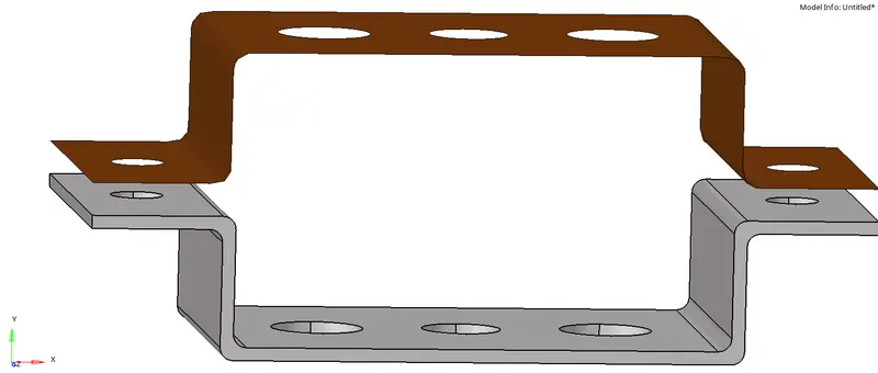
> Before creating 2nd midsurface, create another Component , then create a midsurface for 2nd component.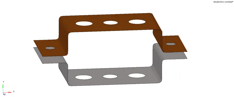
> Usually , 2nd midsurface will be created in collector 1 , so we have to move it into collector 2. we use,
*Tools--Organize--Collectors--Select Surface--Destination (Collector 2). we can observe a colour change.
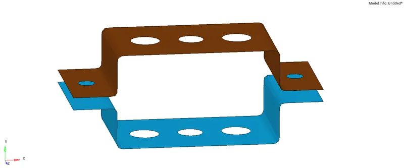
> we have to create washers to all holes (5mm offset)
*Geom--Quick edit--Washer Splits--Select Holes.
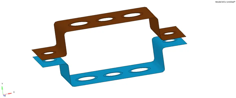
STEP 2 : Creating Material and Properties
> Create a material as Steel and assign this material wherever material is required.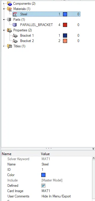
> create 2 properties for 2 components (ref below images).
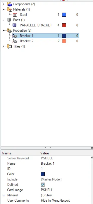
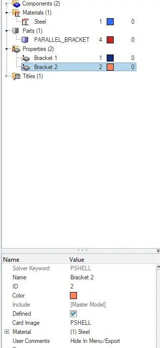
STEP 3 : Meshing
*2D--Automesh--Displayed--element size (5mm)--Mesh 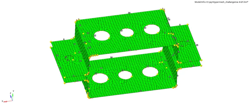
STEP 4 : Creating RBE links
> We have to create RBE Links on each holes as per requirement.
-- Dont create 2 opposite links at same time , go one by one.
a. Rod element:- Translational DOF should be Constrained with RBE2 link
*1D--Rigids--Create Nodes (Calculate--By path)--Create (Update dof).
> Create a element between them
*Rod--Select nodes--CROD--create

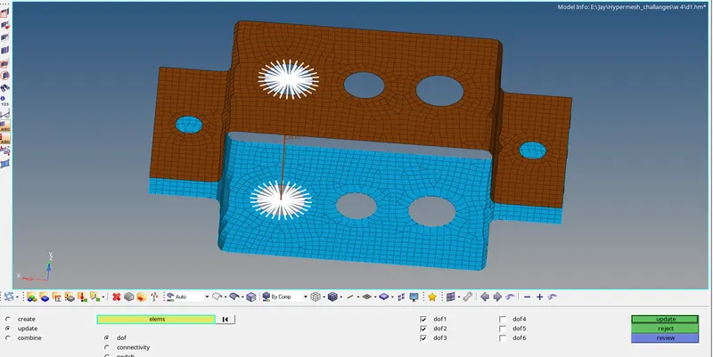
b. Beam element:- All DOF should be constrained with RBE3 link
*1D--RBE 3--Create Nodes (Calculate--By path)--Create (Update dof)
>Create a element between them
*1D--bars--CBeam(Elem type)--select nodes (Orientation)
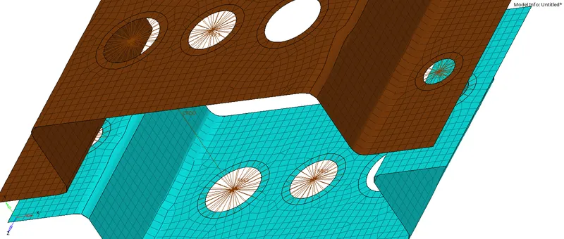
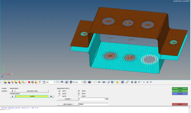
C. Bar element : Constrain only x and y DOFs With RBE3 link
*1D--RBE 3--Create Nodes (Calculate--By path)--Create (Update dof)
>Create a element between them
*1D--bars--CBar(Elem type)--select nodes (Orientation)
STEP 5 : Creating Hperbeams and Properties
a. Rod element:- Translational DOF should be Constrained with RBE2 link
Cross-Section: BOX- Dimension a= 12 mm
dimension b=10 mm
Thickness t= 0.75 mm
* 1D--Hyperbeam--create Hyperbeam--Section type (Ref below steps)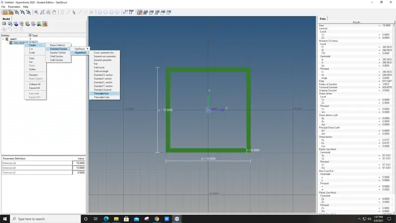
> We have to create new property for rod (Ref below) and assing them property,beam section 
> after assigning them , create rods--the update is visble in mode of 1D Detailed element represntation. 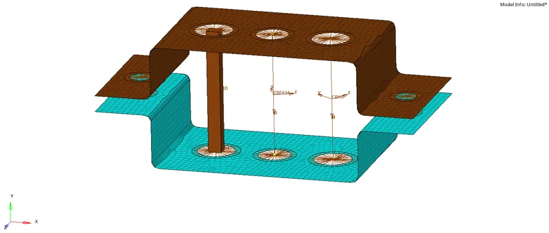
b. Beam element:- All DOF should be constrained with RBE3 link
Cross-Section: I Section- Dimension a= 8 mm
Dimension b= 10 mm
Dimension c= 8.5 mm
Thickness t1= 0.75 mm
Thickness t2= .6 mm
Thickness t3= .6 mm
*1D--Hyperbeam--create Hyperbeam--Section type (Ref below steps)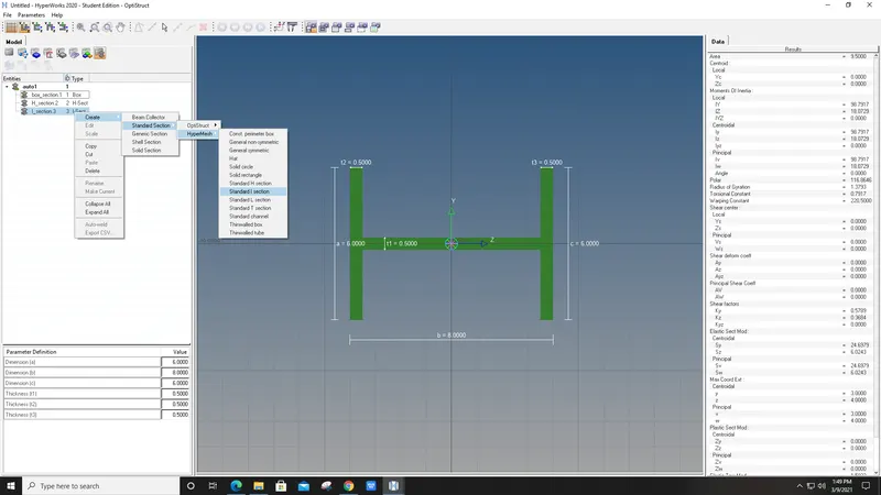
> We have to create new property for Beam (Ref below) and assing them property,beam section (Similar ealier in Rod , ref it)
> after assigning them , create Beam (Orientation)--the update is visble in mode of 1D Detailed element represntation.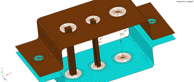
c. Bar element:- Constrain only x and y DOFs With RBE3 link
Cross-section: X section- Dimension DIM1= 5 mm
Thickness DIM2= 1.2 mm
Dimension DIM3= 10 mm
Thickness DIM4= 1.2mm
*1D--Hyperbeam--create Hyperbeam--Section type (Ref below steps)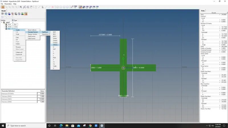
> We have to create new property for Bar (Ref below) and assing them property,beam section (Similar ealier in Rod , ref it)
> after assigning them , create Bar (Orientation)--the update is visble in mode of 1D Detailed element represntation.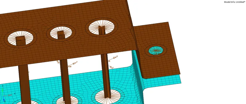
d. & e. Apply the mass of magnitude 10 with the RBE2 link
>Create rigids on hole to be placed with masses
*1D--rigids--RBE 2--Create
*1D--Masses--on top node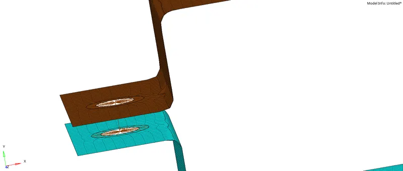
f. Join the two components with Spring elements
*Springs--select two nodes--create.
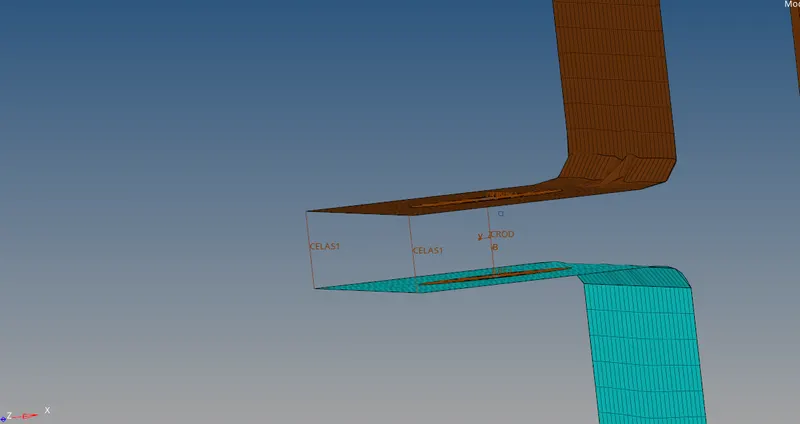
FINAL View :