Week 9 - Project - Master Section Development
AIM : To create a B-Pillar Master Section development through a given Class-A surface
INTRODUCTION
B-Pillar is the vertical structure between the front and back seat door of a car. It connects and provide support to the roof.
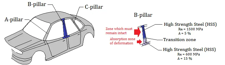
MASTER SECTION
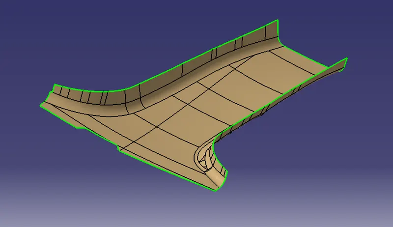
Master Section is the guide for designing requirments which shapes the component after styling of Class-A Surface.
RIBS
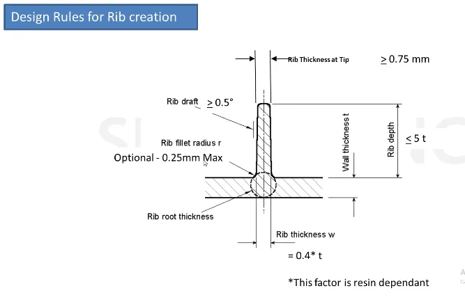
It Provides extra Strength and Stiffness in molded part without increasing the overall wall thickness.
RIBS Design Rule
- Draft angle = 0.5degree
- Thickness = 0.4*t (t= component wall thickness) ie, 40% of wall thickness
- Minimum thickness at Top = 0.75mm
- Fillet Radius = 0.25mm
- RIBS Height < 5 times of wall thickness
DOG-HOUSE
Dog-House is the Engineering supporting feature used in Plastic Designing.
- It helps to avoid sink marks.
- It also provide enough strength to joinn different surface having large distance between them.
Designing Rule
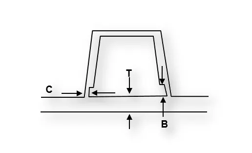
- Dog-House wall thickness = 0.4*T (T=thickness of component)
- Height(B) = 3 to 6 mm
- steel Width/Height ratio = 3:1
- 'C' is where Doh-House contacts the backside of the surface.
PROCEDURE
TOOLING AXIS
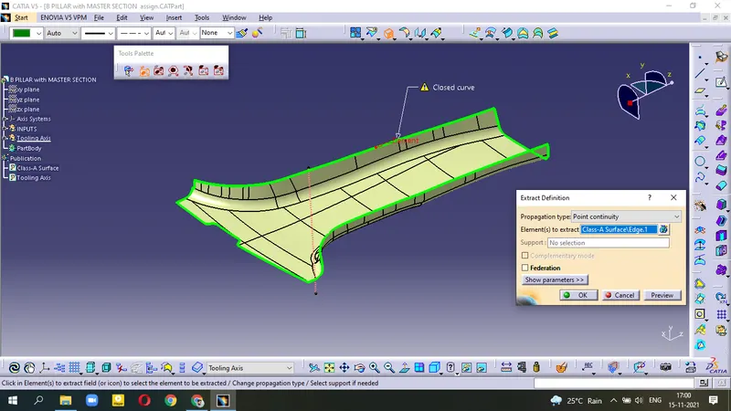
- Extract the curves
- Create two points by using between points option and BISECT the two lines along this point.
- similarly BISECT other two lines
- the resultant of these two BISECT lines is our TOOLING AXIS.
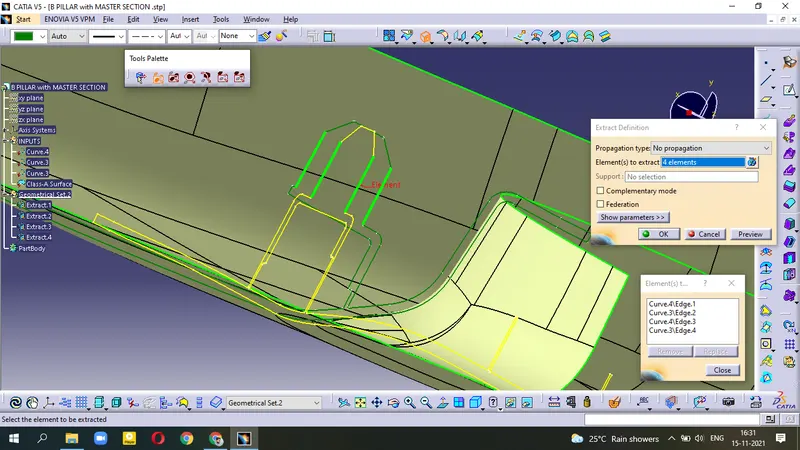
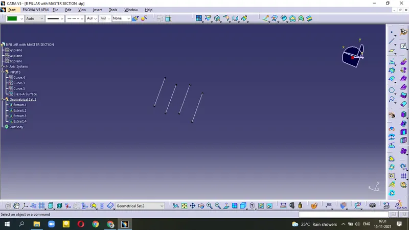
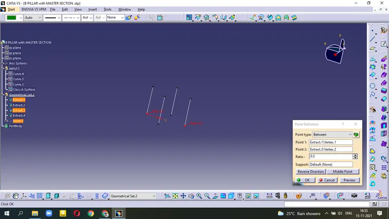
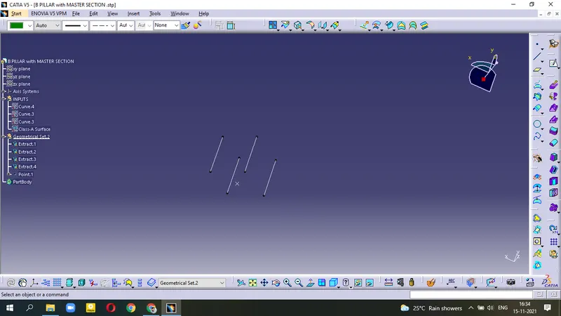
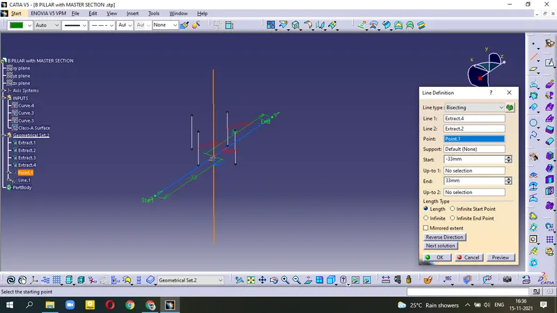
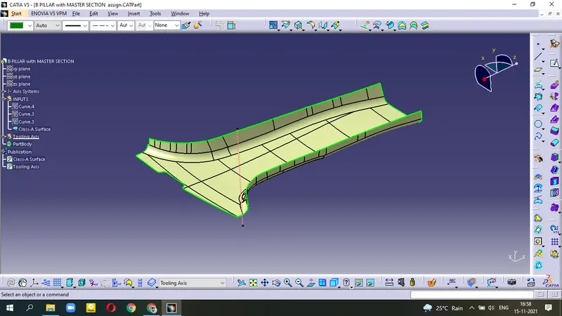
Tooling Axis is in doted Pink colour
FLANGES
From below figure, we need to create the Flanges on both left and right side as per required length.
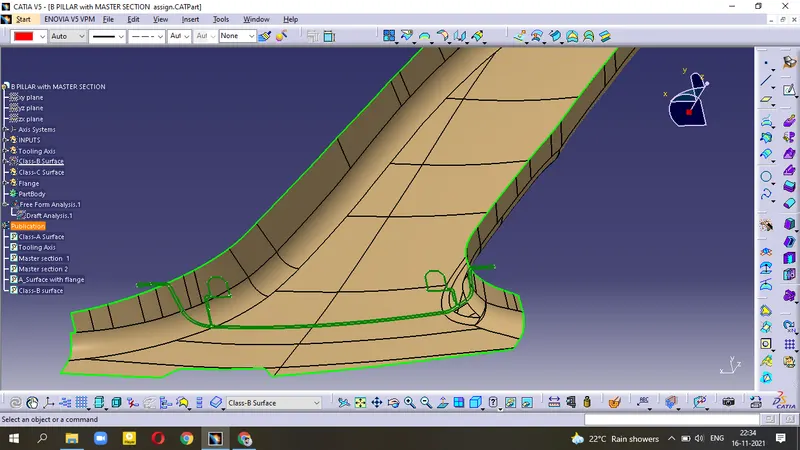
- create the Plane by using plane type = through three points
- make the Intersection on Class-A surface by using plane.
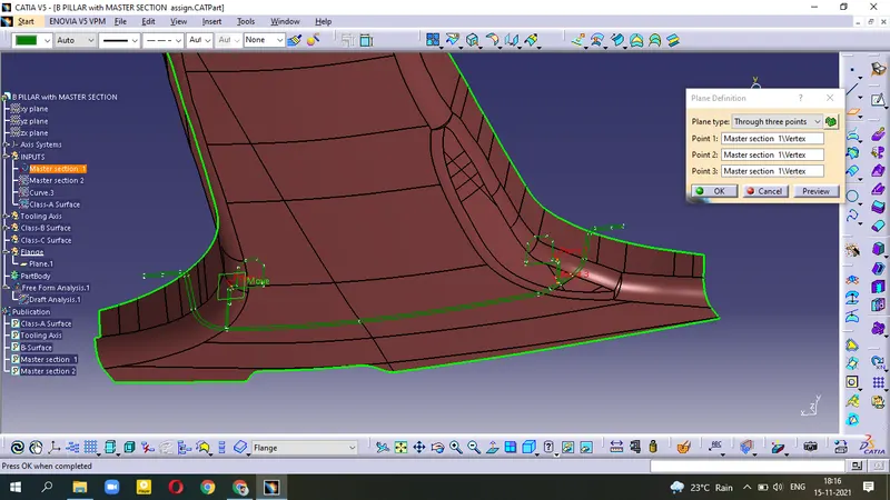
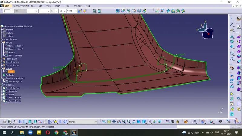
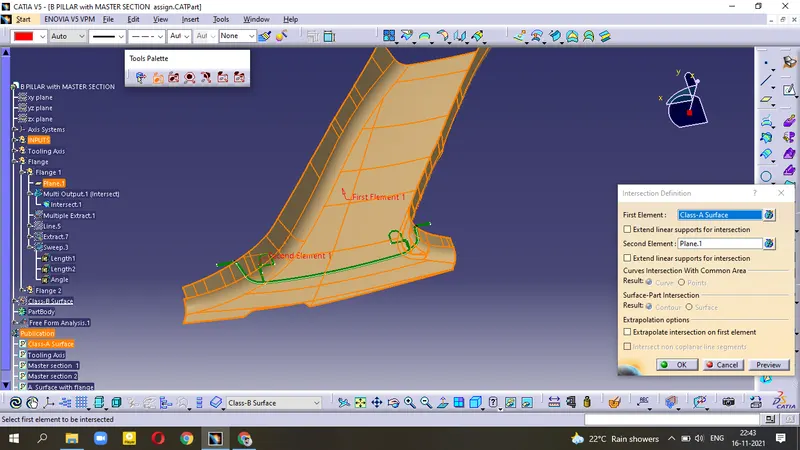
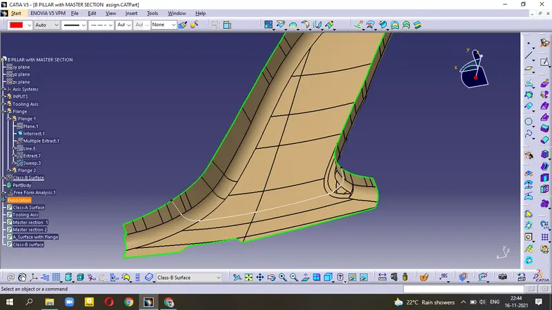
- use Extract for the corner edges and Multiple Extract for the surface.
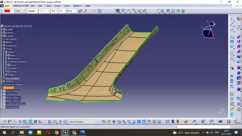
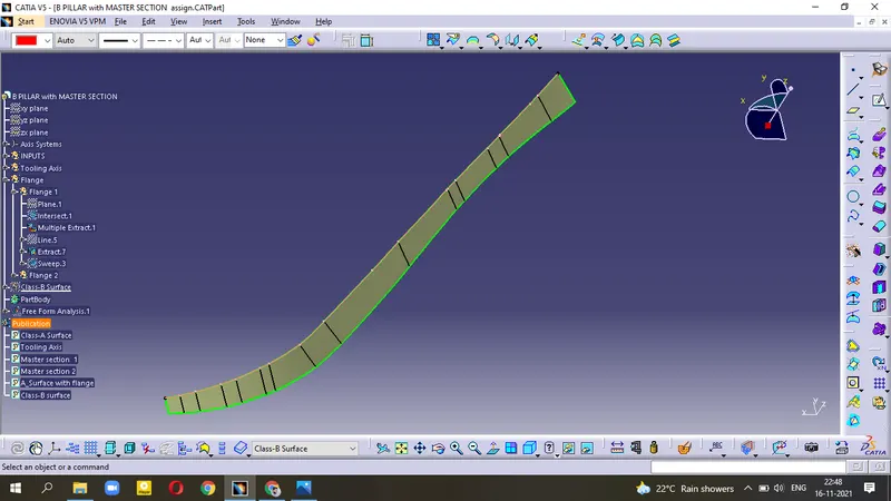
- Sweep outward side by using with reference surface
- j
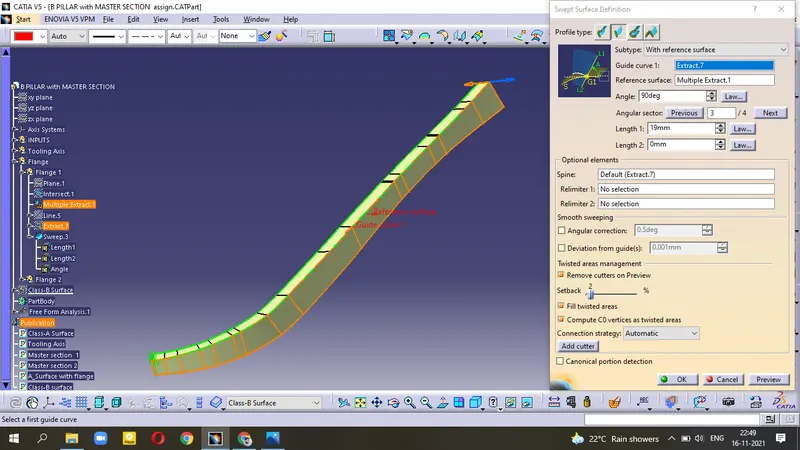
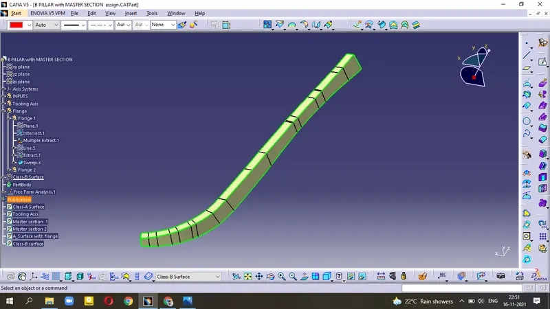
Similarly
FLANGE 2
- EXTRACT corner edges and Multiple Extract the surface.
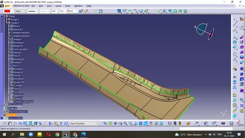
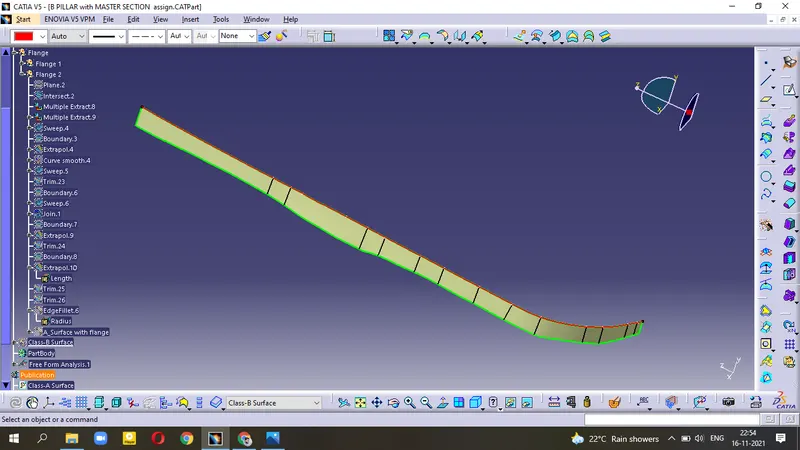
- while Sweeping, it is showing Error because of the styling curves.
- hence, Extrapolate the extracted surface and Sweep at 180degree for Class-A surface.
- JOIN this sweep surface, Class-A surface together.
- use Trim for this joined Class-A surface and Multiple extract surface.
- we get our 2nd Flange.
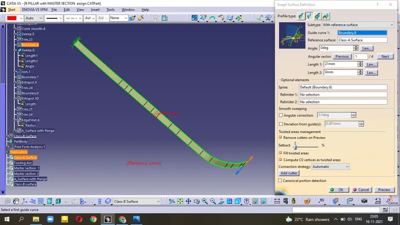
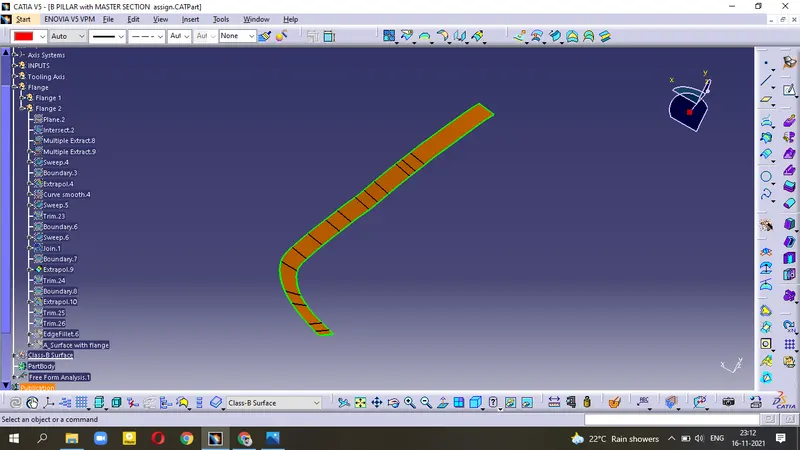
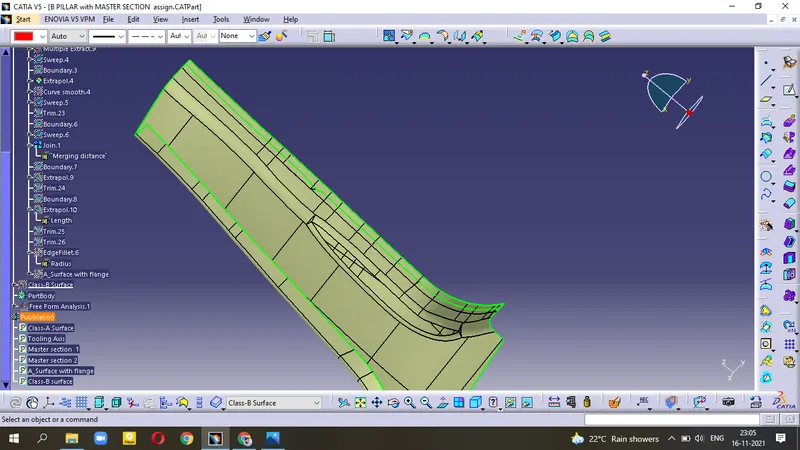
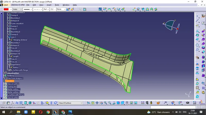
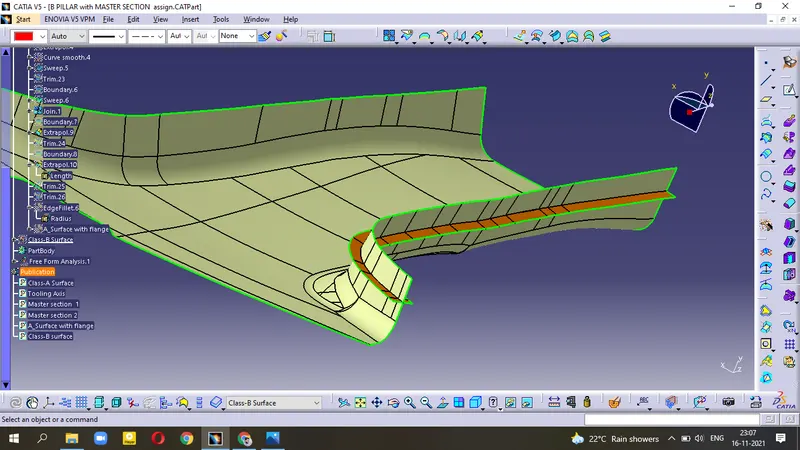
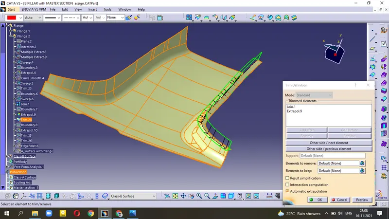
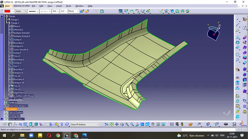
- now, use TRIM with the other 1st flange.
- apply Edge Fillet at the corners.
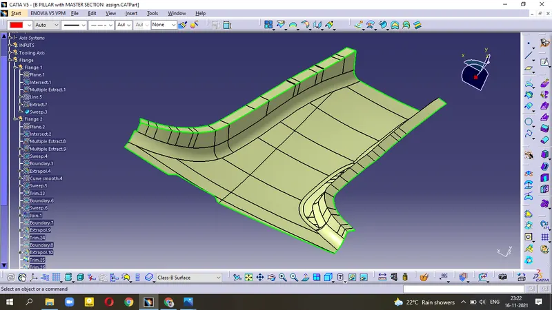
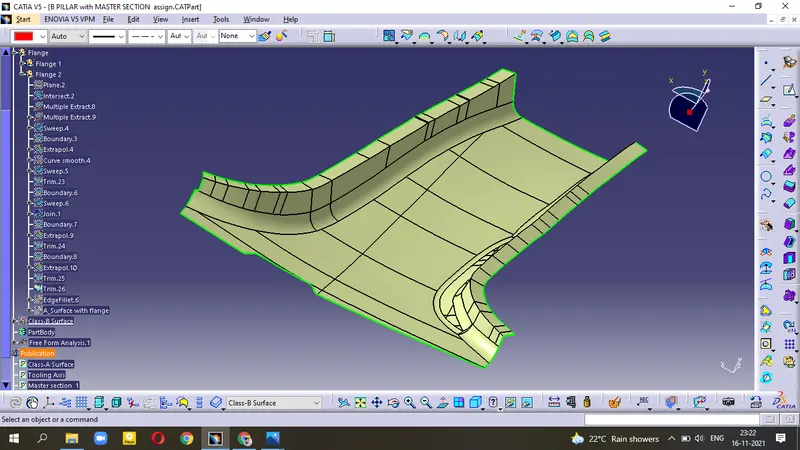
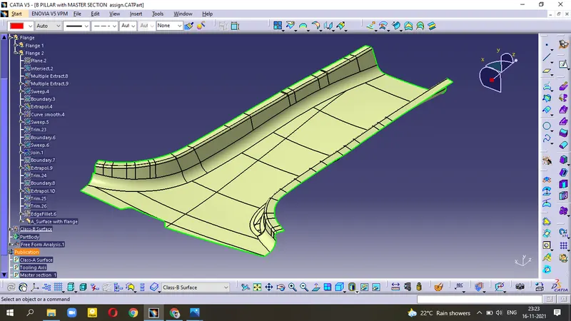
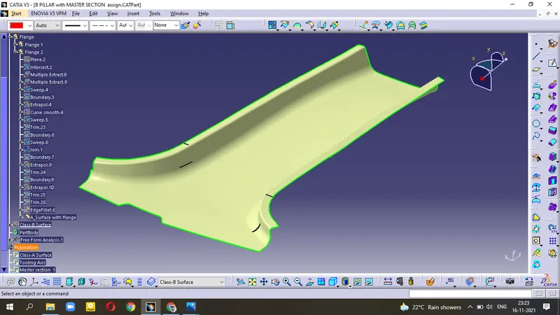
Final Class-A surface with Flange
Draft Analysis
- Create the Boundary over the Class-A surface; for checking surface quality. if NO patches found then our surface quality is good.
- Create Draft Analysis.
- Draft angle = 3degree
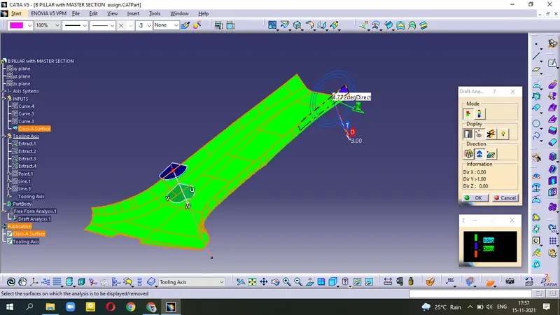
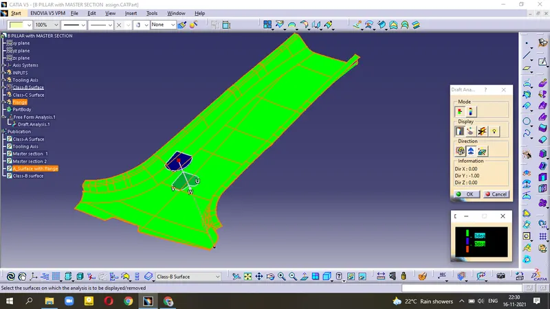
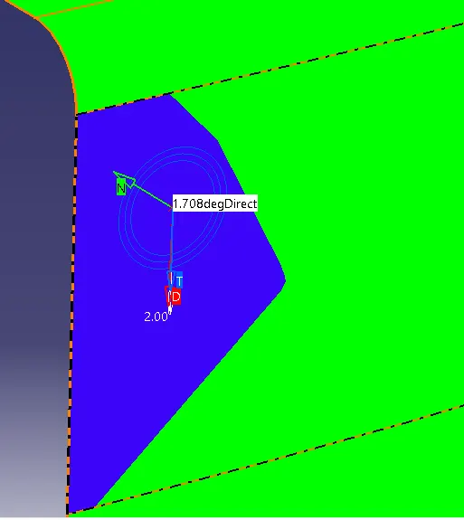
All faces have 3 degree Draft but in this patch it is 1.7 degree
Class-B surface
for creating Class-B surface, we normally use for surfaces, fillets EXTRACT - UNTRIM - OFFSET - TRIM . But in this Master Section surface, there is so many fillets, stylling features which are not easy to get our desired surface by above steps. so, we directly OFFSET = 2mm Class-A surface to get our Class-B surface.
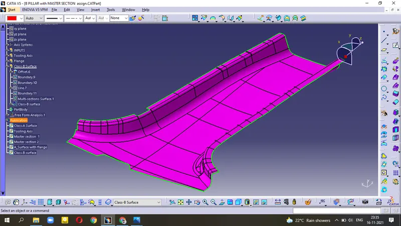
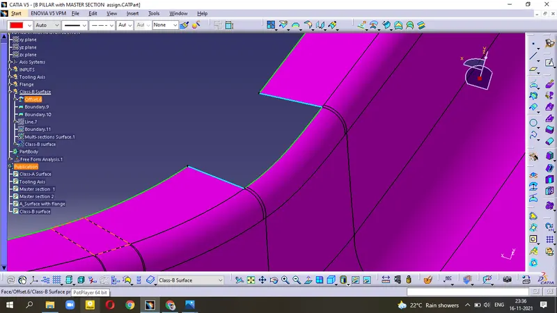
- Improper edge is present. To improve this, we use Boundary at all three corner-edge then create Line in other direction to make the closed profile.
- use Multi-section surface tool to create the surface within this boundary. make sure both arrow in same direction.
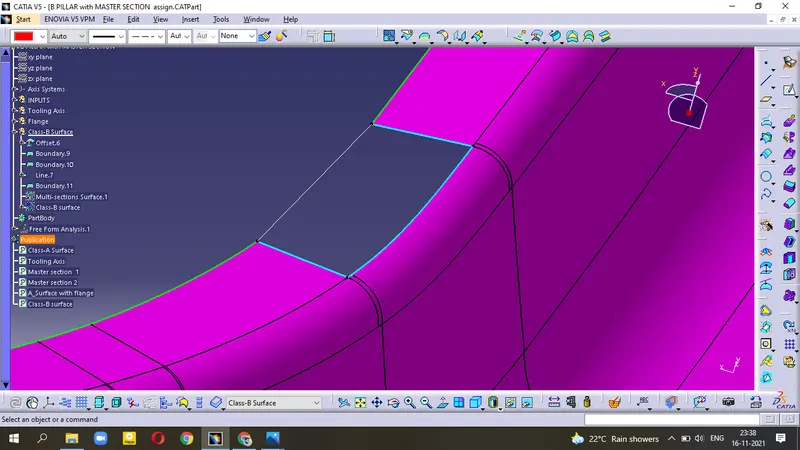
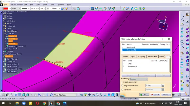
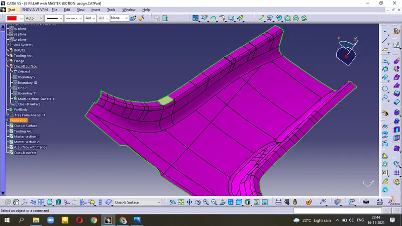
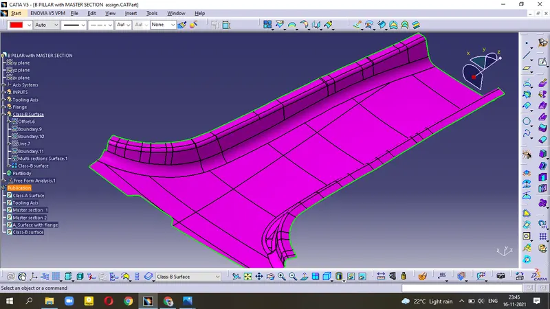
Final Class-B surface
Class-C surface
- unhide Class-A and create Boundary on the surface.
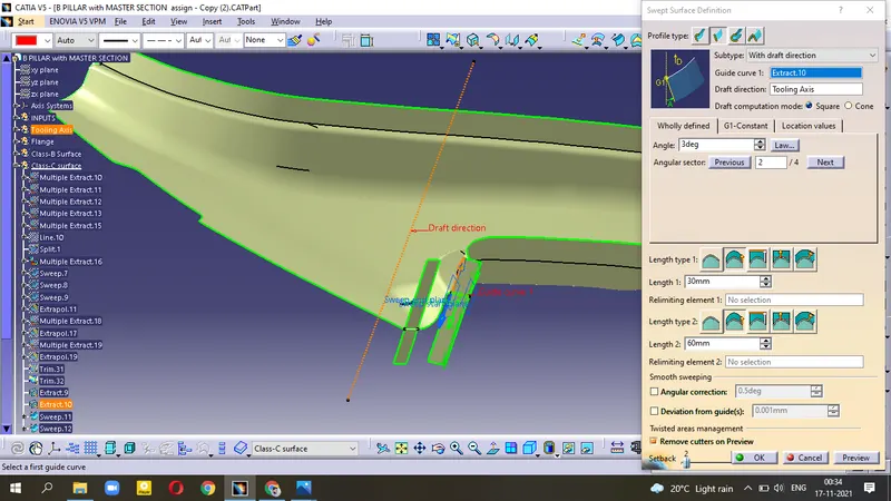
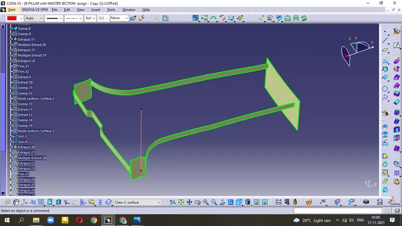
- apply SWEEP operation at angle=3degree along Tooling Axis for all created Boundary.
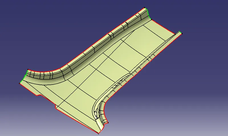
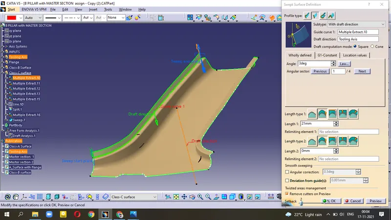
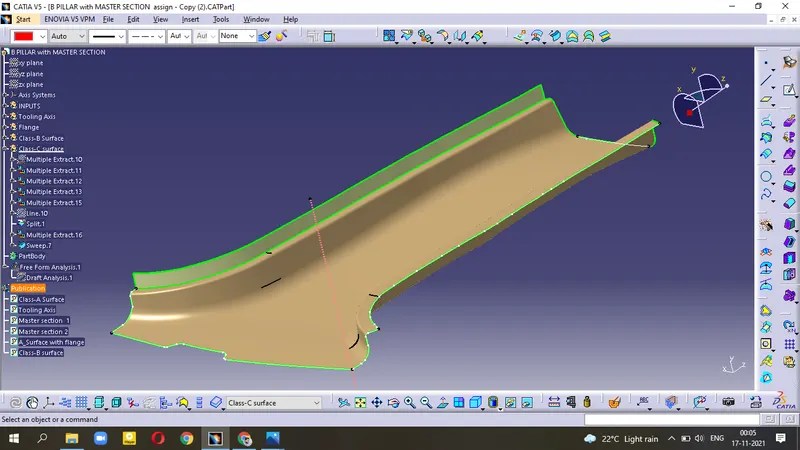
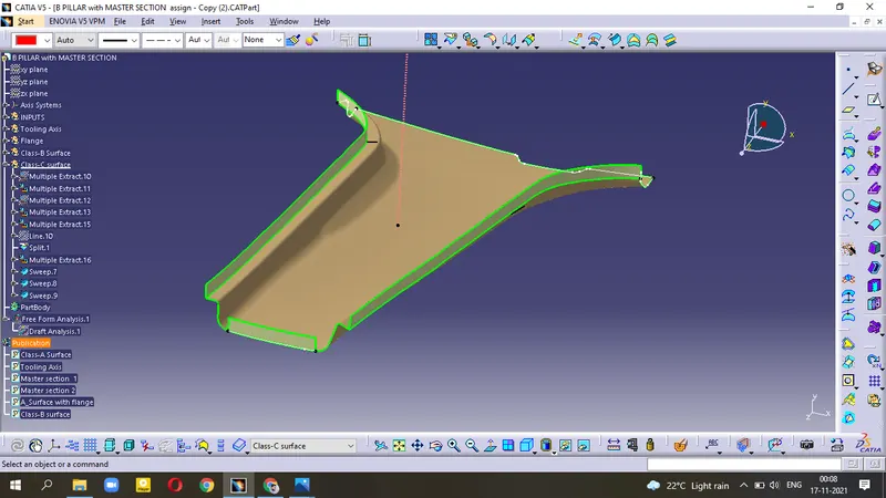
- we face difficulty on Sweep operation on the curved surface.
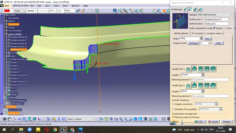
So, Try different method
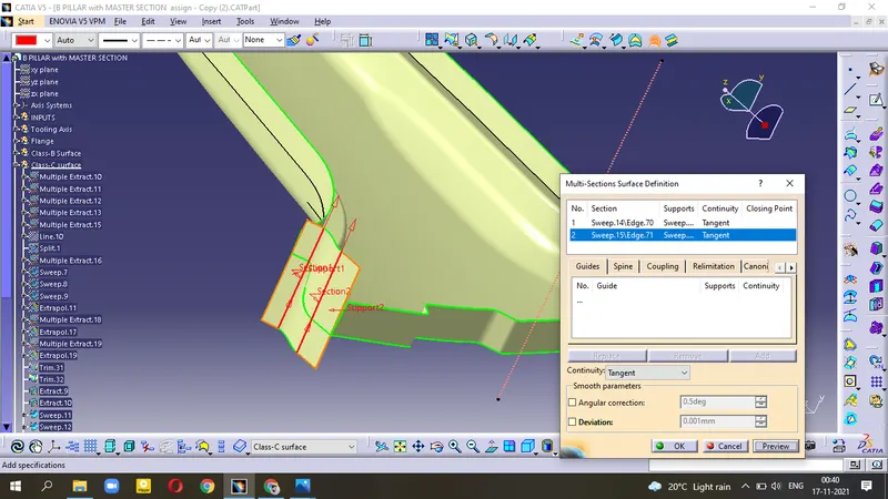
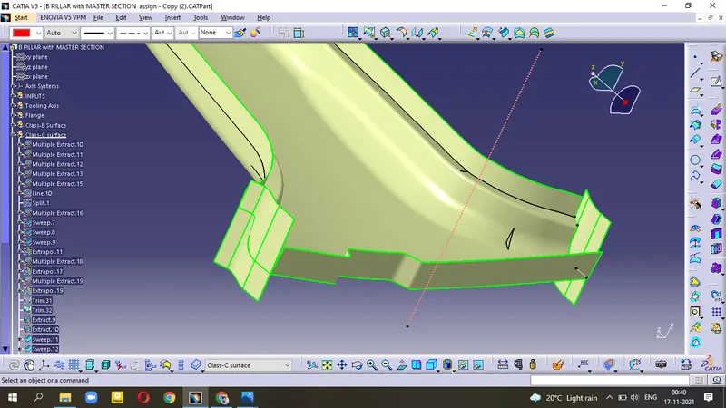
- Apply Boundary, then Sweep in vertical direction but the length should be equal.
- use MULTISECTION SURFACE and then JOIN together.
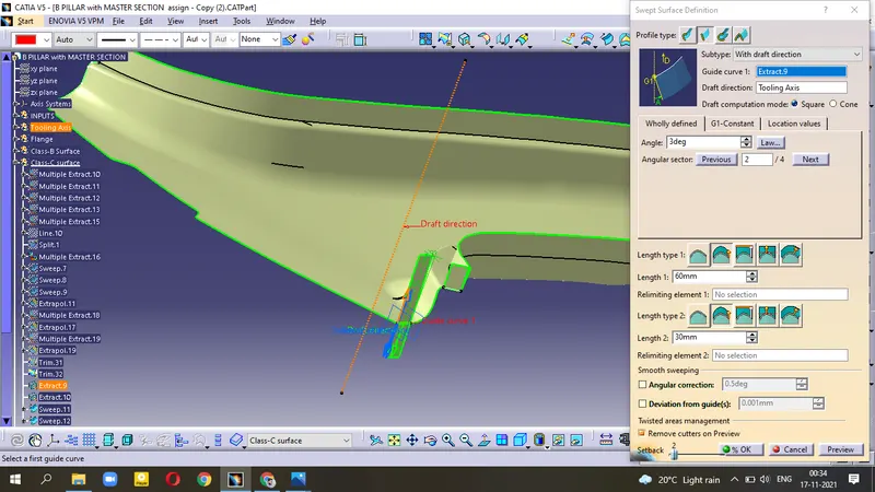
Similarly,
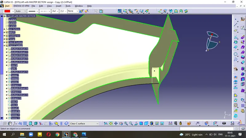
- use operations - Boundary, Extract surface, Sweep, Extrapolate, Multisection surface, Split, Trim for getting Class-C surface.
now,
Final join
- Join this C-surface with Class-A surface by using Trimming operation because of the presence of more curves.
- Trim the Class-B surface with the Class-A surface along with C-Surface.
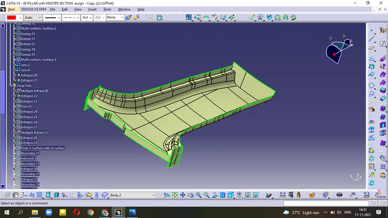
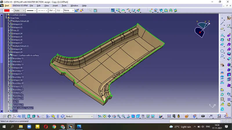
Final C-surface along with A-Surface
- unhide Class-B
- Trim Class-B surface with Final C-Surface along with A-Surface.
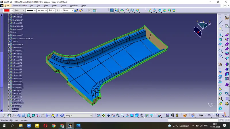
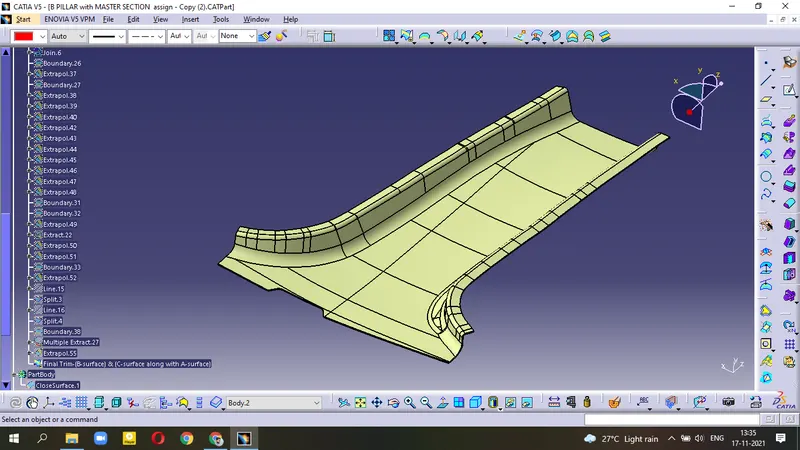
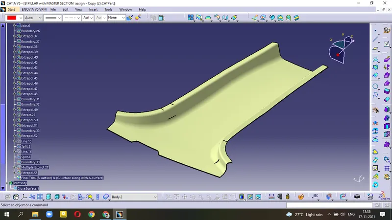
Final Trimmed Surface
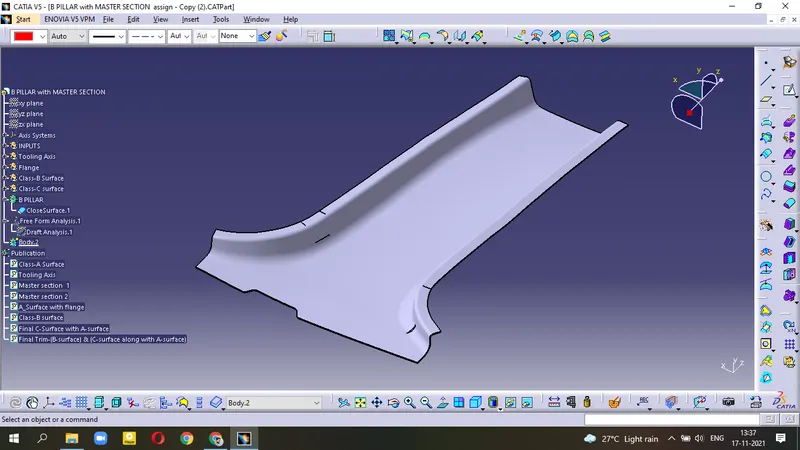
- Insert a body and make it a Solid Body which is our B-PILLAR
Draft Analysis
- Allign the Compass properly.
- Make the draft Analysis along Tooling Axis , It is showing some patches. Try it reducing by minimise draft angle. We can aiso tell the Design Engineer about this.
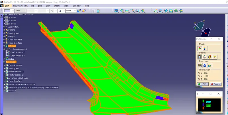
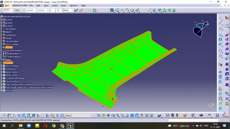
The Green Draft colour should be in A-surface and C-surface so Inverse Draft direction.
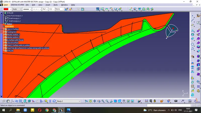
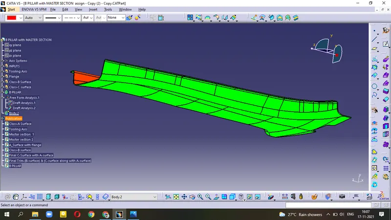
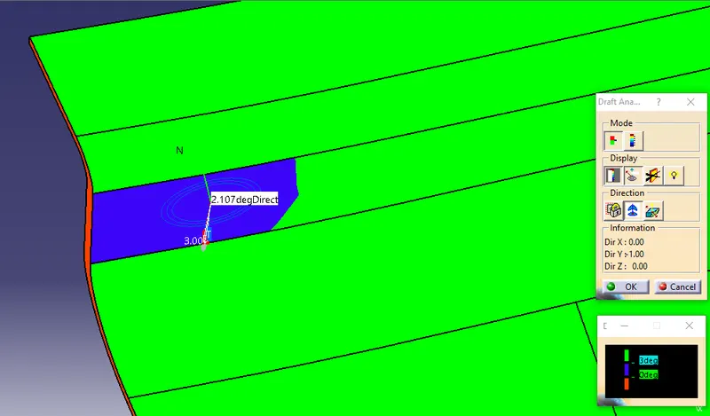
All faces have Draft angle = 3degree, but this patch has Draft angle = 2.1degree
B_side Feature
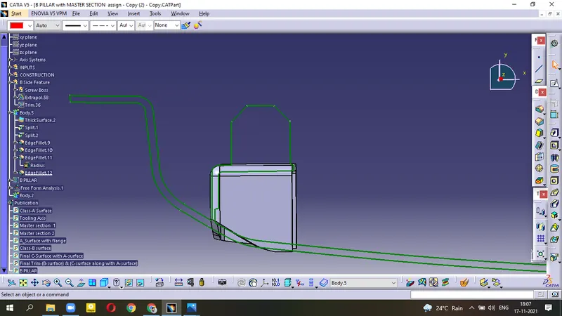
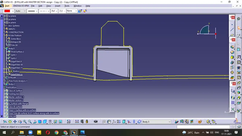
DOG-HOUSE
- unhide the Master section curve
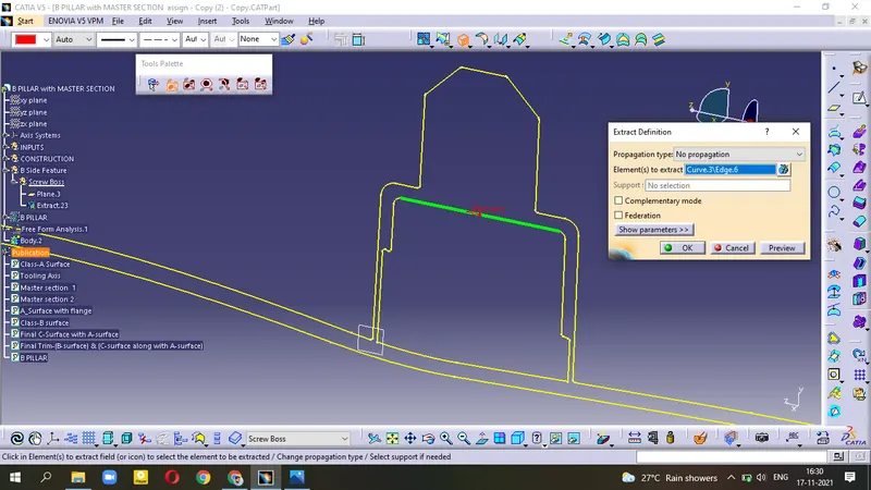
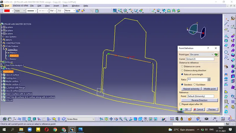
- Extract upper line and create a point in the middle.
- create a plane in YZ-direction at a middle point.
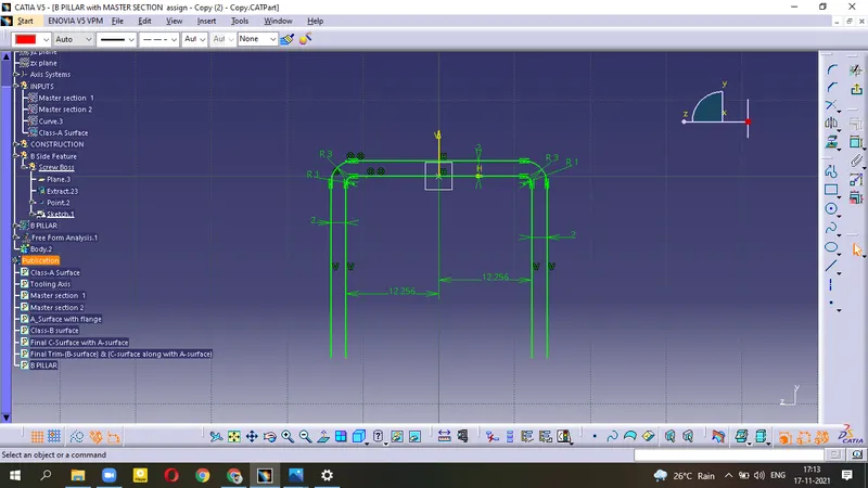
- start sketching by using Positional sketch
- Project 3D of Master section curve
- Extrude the sketch
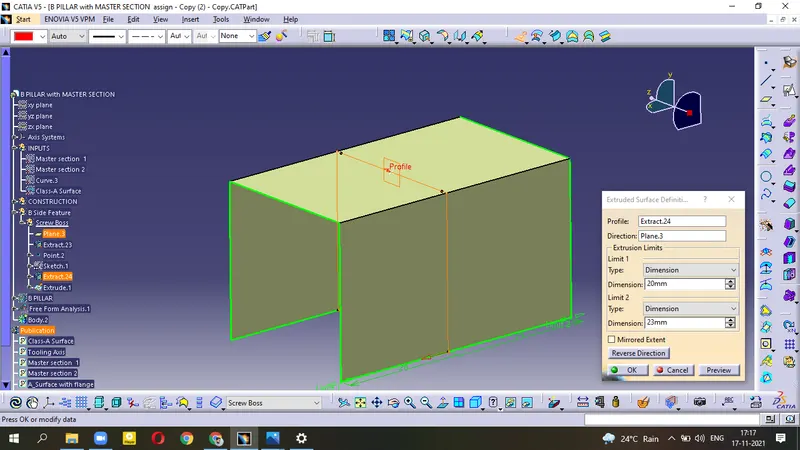
- Extract other two lines and by Extruding, Split the above surface.
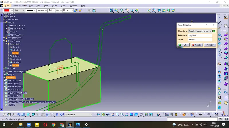
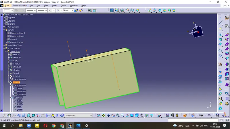
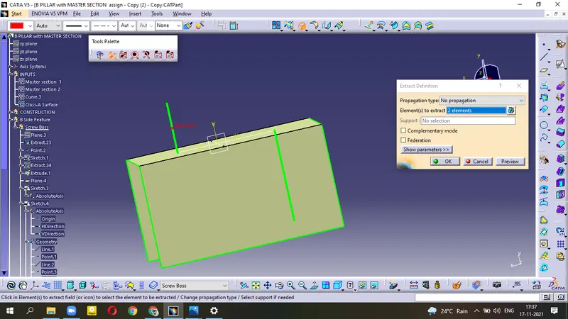
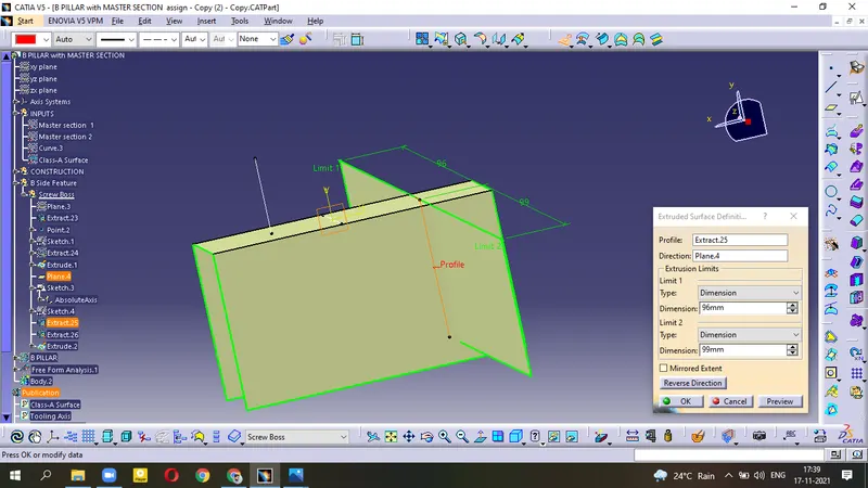
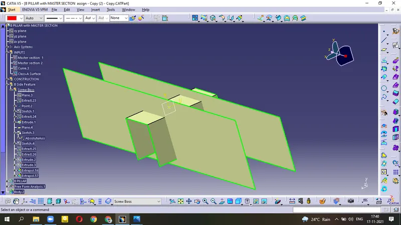
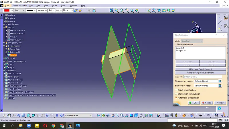
- make the profile Solid in Part design by using Solid Surface
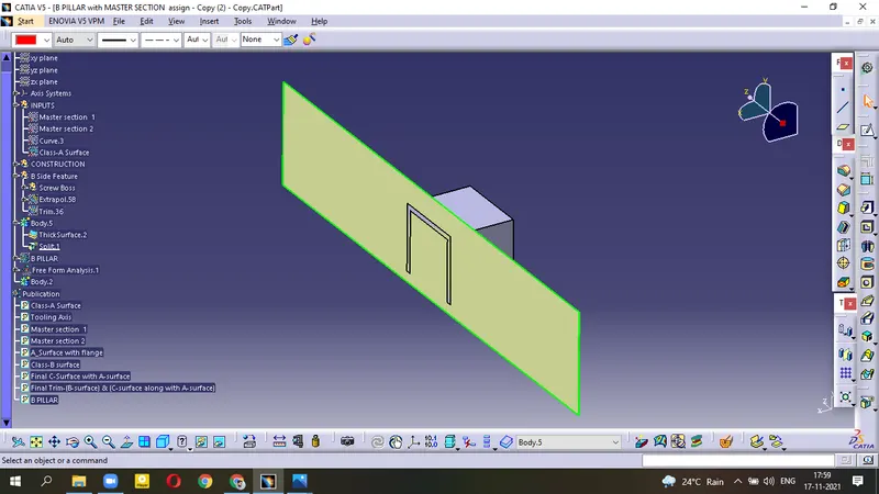
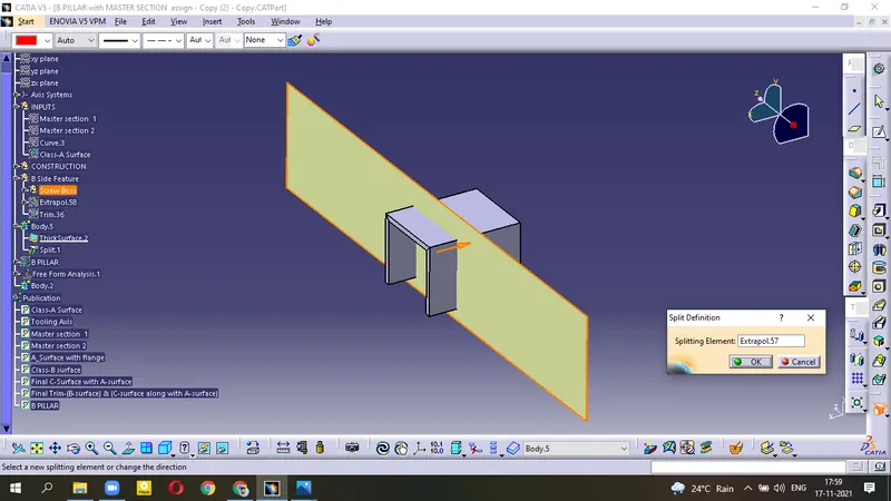
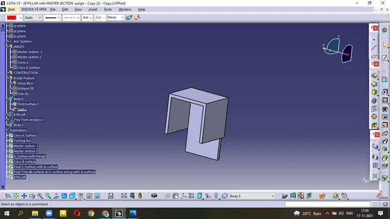
- unhide Class-A with Flange surface and Split this Screw Boss solid.
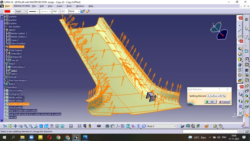
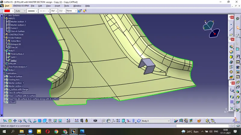
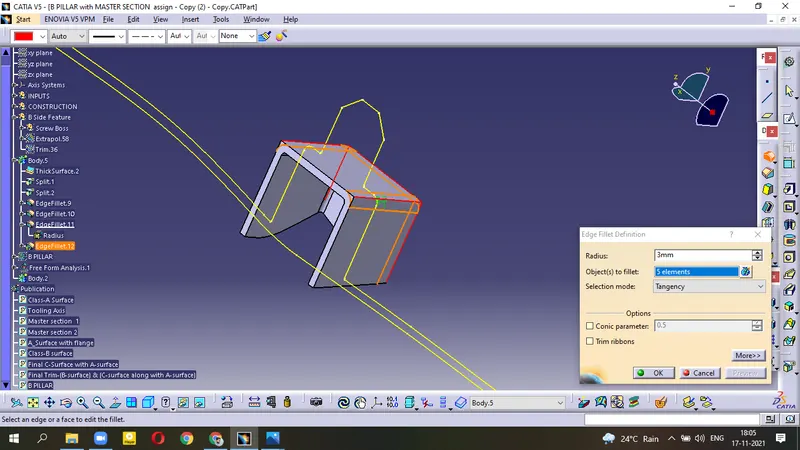
- Apply Fillets and Visualise with our Master Section curve.
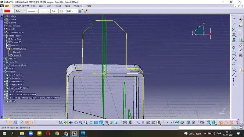
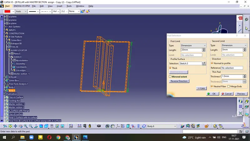
4-WAY LOCATOR
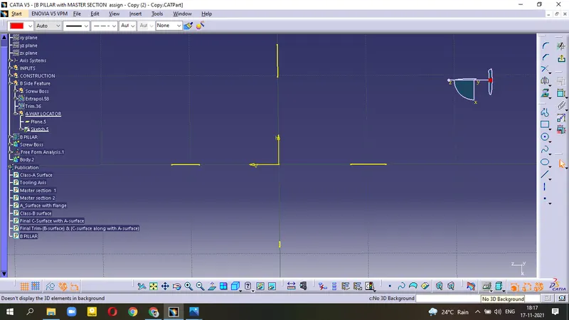
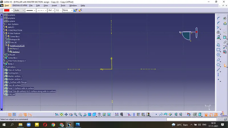
- Create point by using Projection 3D of Mastersection curve.
- make a ZX-plane.
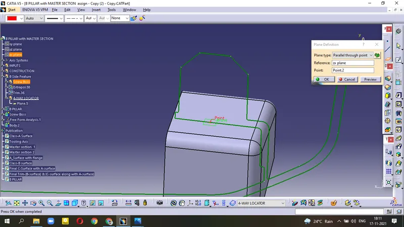
- Project 3D Horizontal Master section curve line.
- make these offset under Construction Element
- create sketch
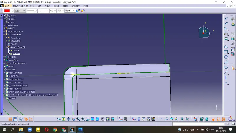
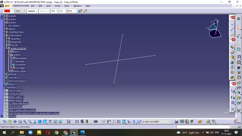
- Extrude the line
- apply proper Edge Fillet
- Draft angle = 0.5degree
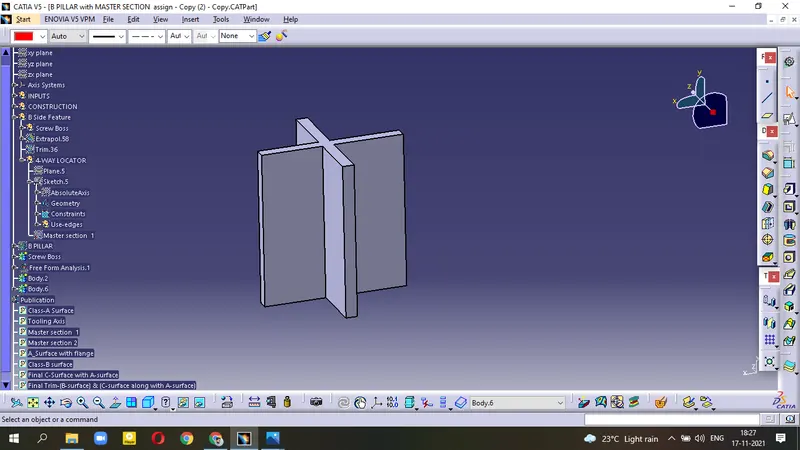
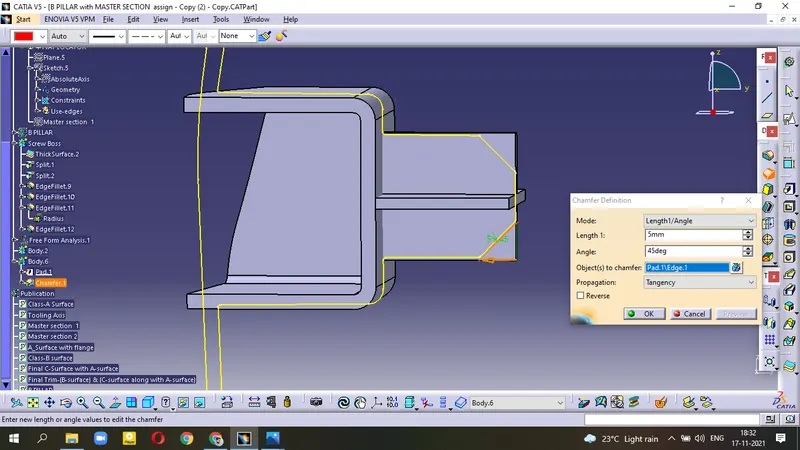
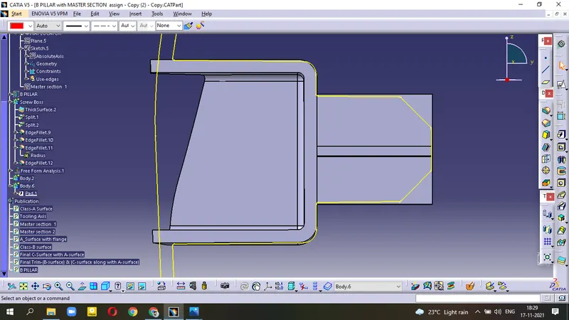
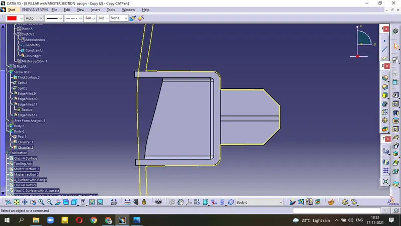
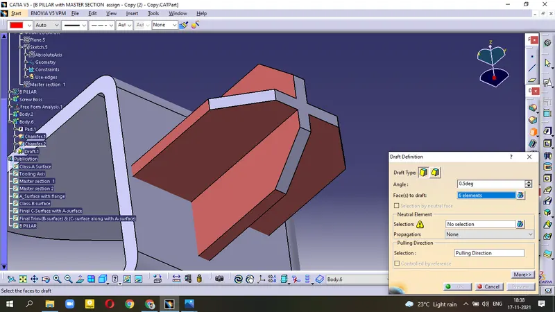
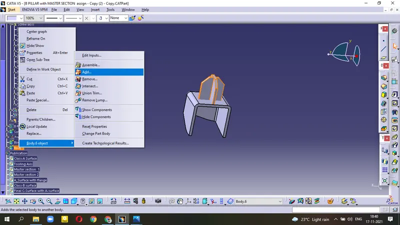
- Add this body with the Screw Boss.
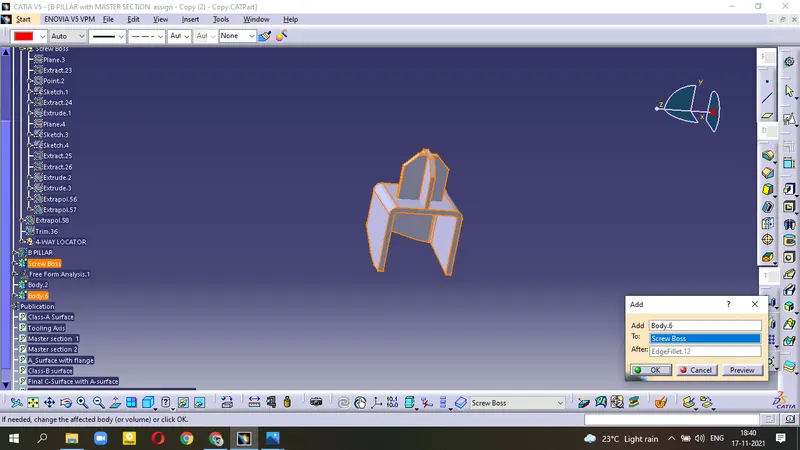
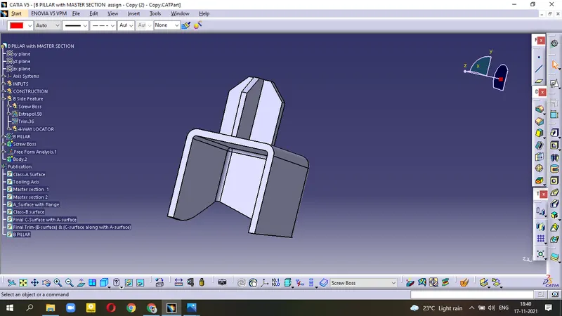
- Apply fillets =0.3mm , Chamfer=3mm at the Edges
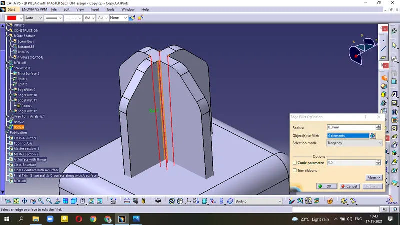
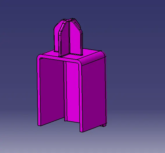
This is our DOG-HOUSE
now,
- unhide B-surface and Extruded Screw Boss
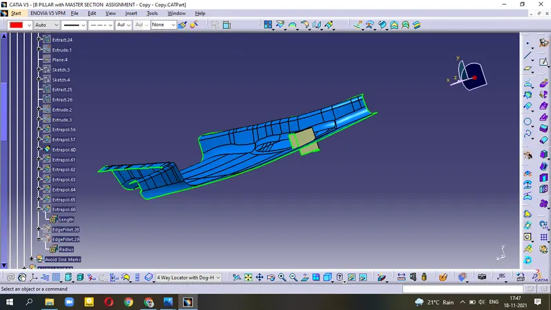
- Multiple Extract the surface of B-surface arround the Extruded Screw Boss
- Offset the Extract Screw Boss = 1.2mm, Extracted B-Surface = 5mm
- use Trim operation
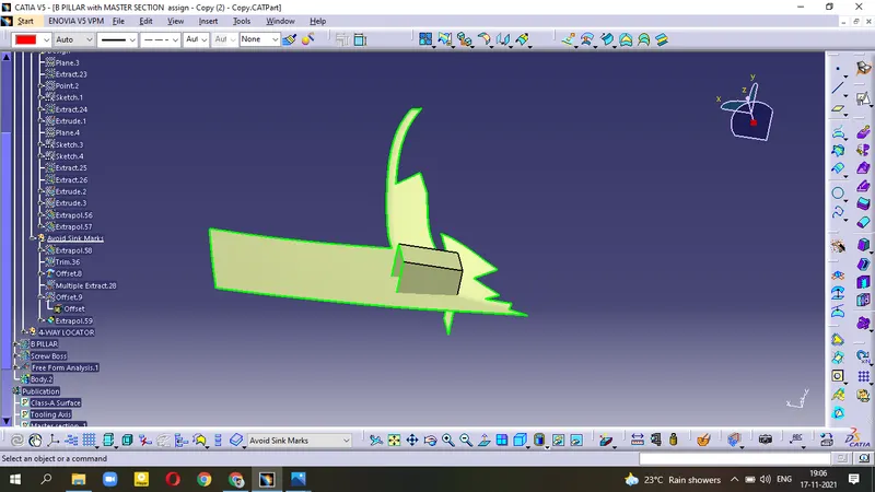
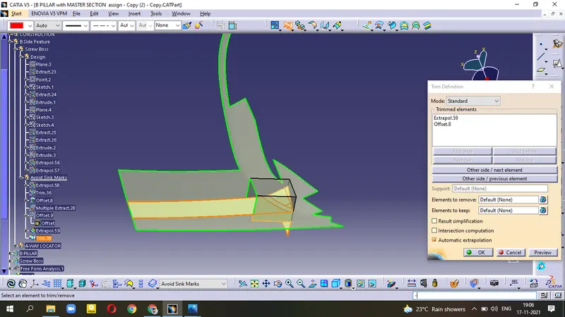
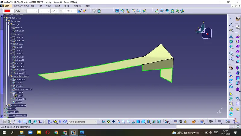
- unhide Extruded surface of screw Boss
- use Split operation
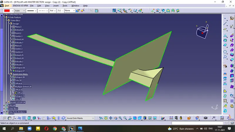
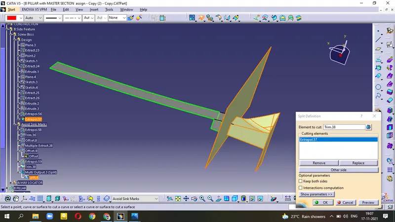
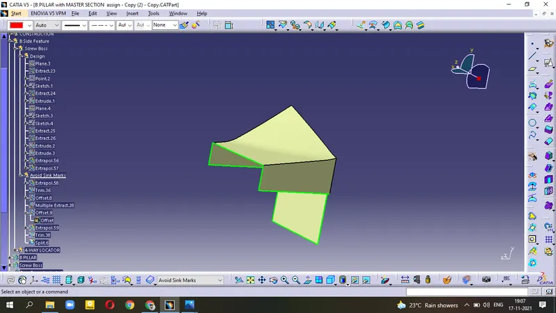
Avoid Sink Mark
- unhide Solid Dog-House
- Split this solid surface in part Design with above surface.
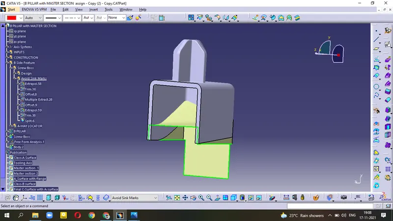
- apply Fillet in Edges
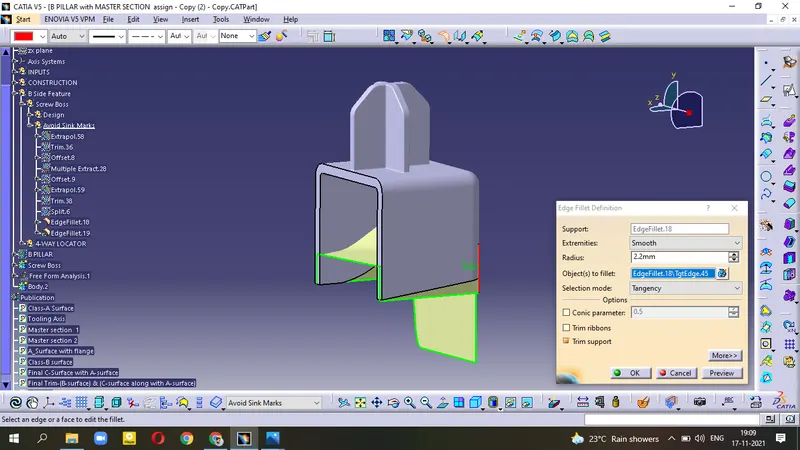
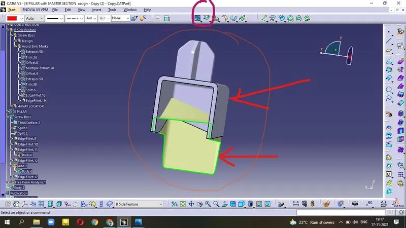
(NOTE - We can't Split a surface with the solid surface in Shape Design, we can split this in Part Design)
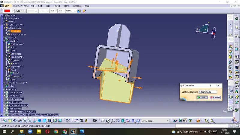
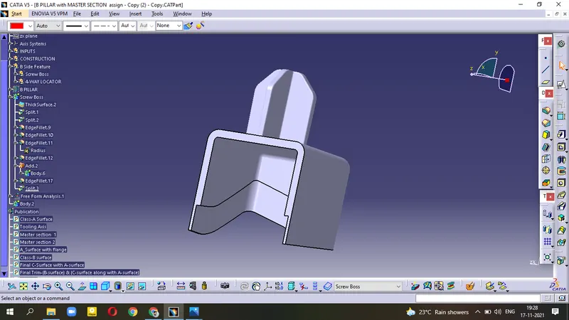
Draft Analysis
- Allign the Compass proprly
- Check Draft Analysis along Tooling Axis and Lifter Axis.
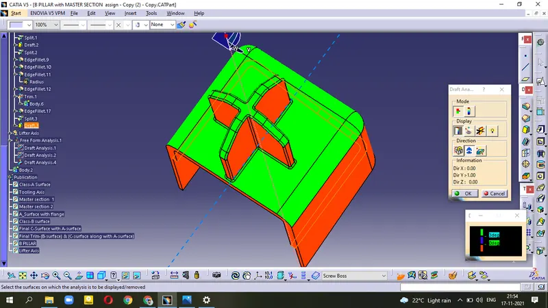
Along Tooling Axis
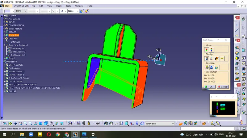
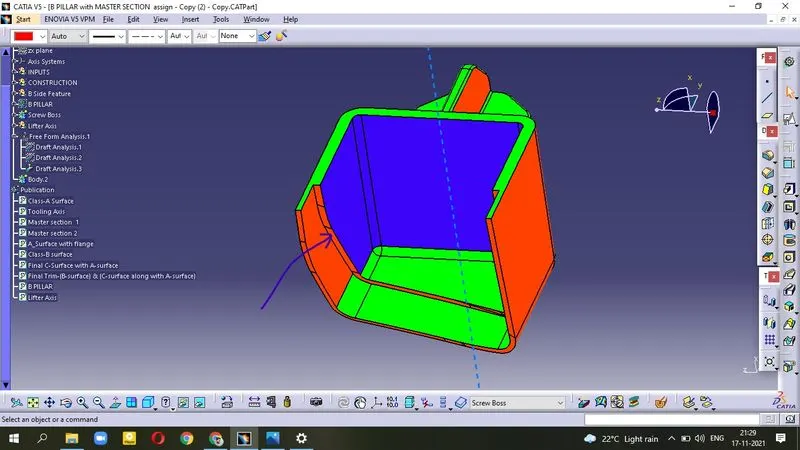
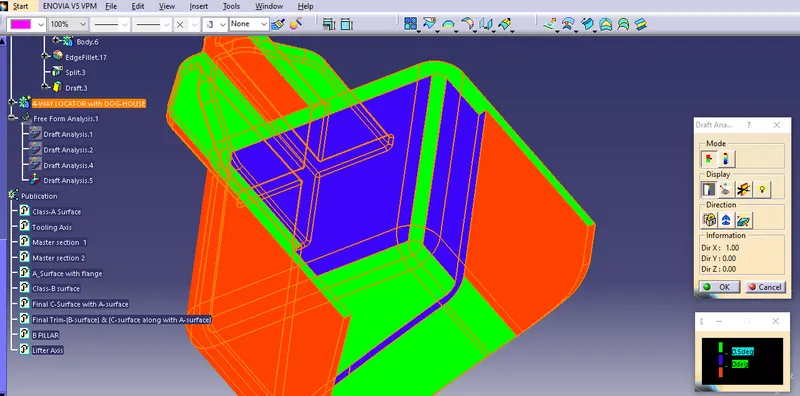
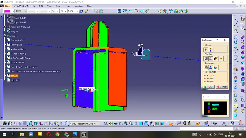
Green faces Cleared with Draft angle =2.9degree, Blue face having Draft = 0.5degree
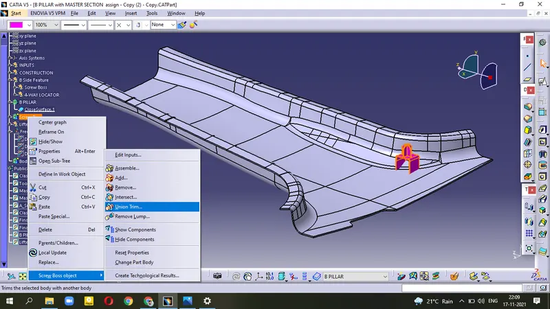
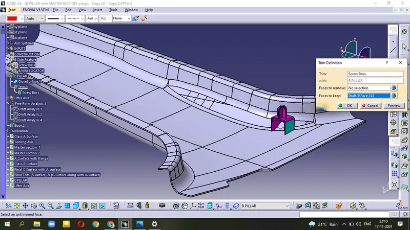
- Dog-House : Insert in new to form Boolean operation,
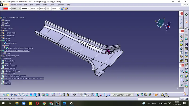
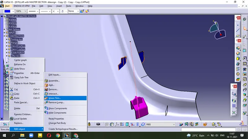
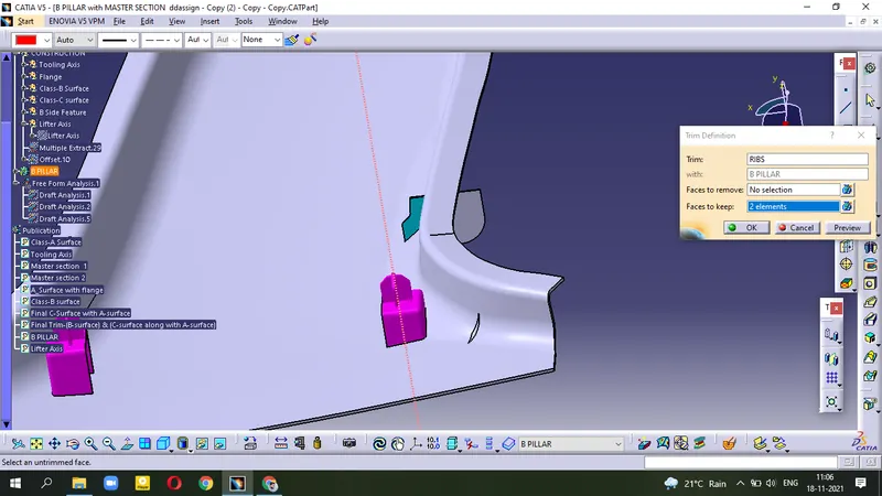
- Union trim with B-PILLAR.
LOCATOR 2
- unhide Mastersection curve, and create a point, a plane
- use Symmetry to mirror this Dog-House in opposite side.
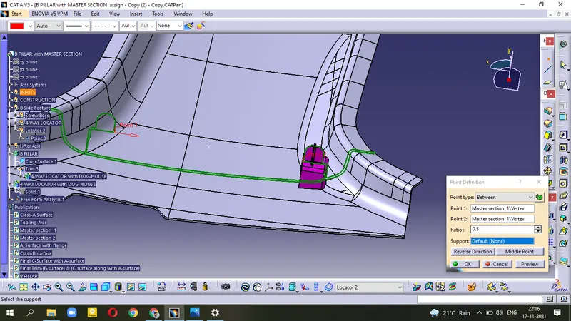
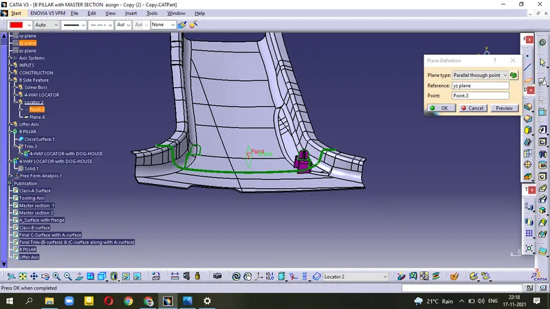
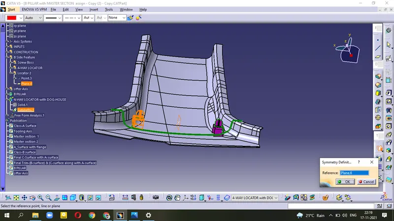
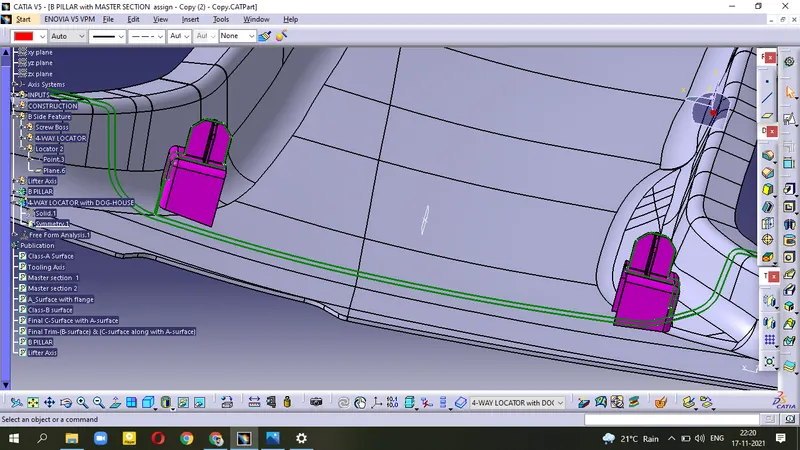
- edit, delete the Split operation to join other side Dog-House properly with B-PILLAR.
(NOTE - After using Union Trim we can delete the split operation because it is now totally attached with B-PILLAR. so deleting these will not affect to our main current body )
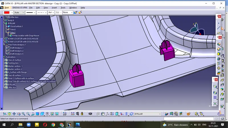
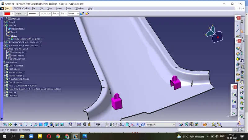
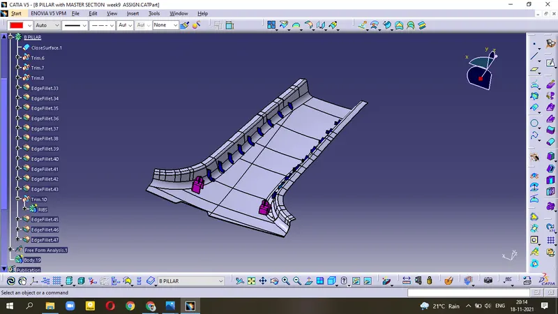
RIBS Creation
- unhide Point, Plane on the Dog-House.
- Create Position Sketch with point, plane
- Extract the Line and use Extrude
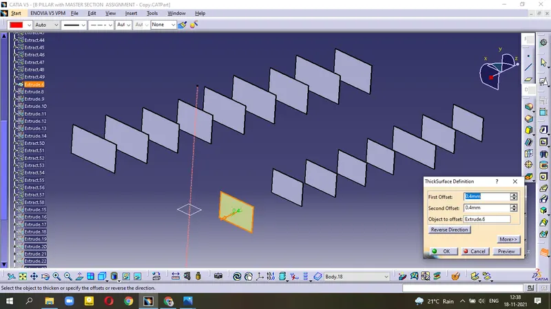
- apply Thickness to the surface
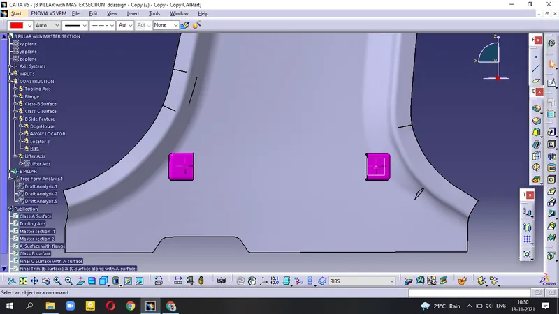
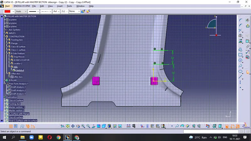
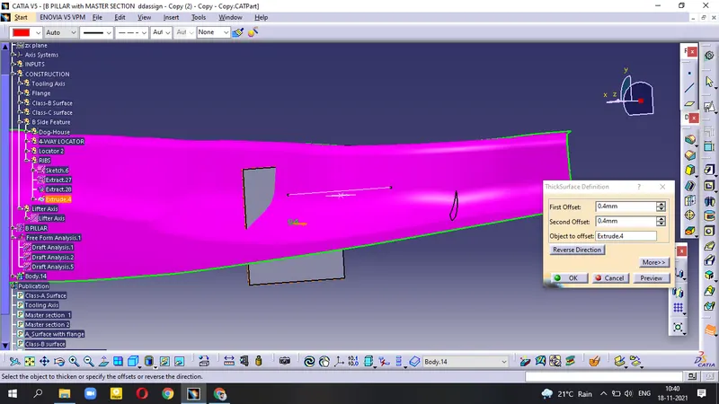
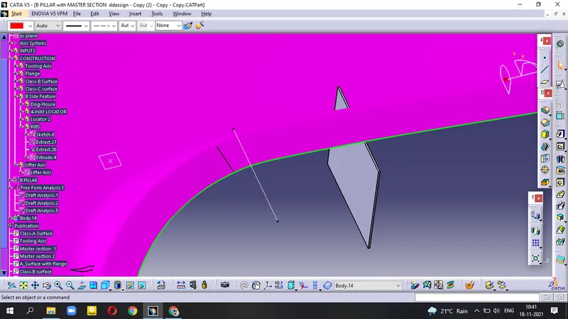
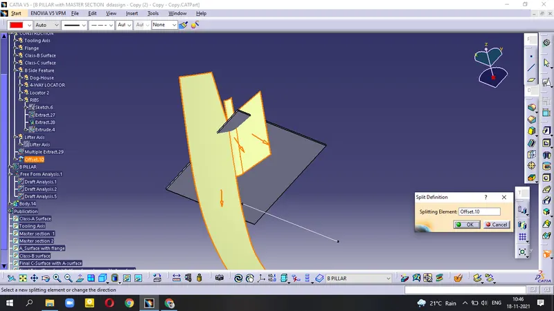
- Use Multiple Extract on the surface of B-surface arround this Rib Thick body
- OFFSET = 10mm of this extracted surface. (because of Design rule- Height should be 5 times than Rib thickness ; t=2mm)
- Use Split operation
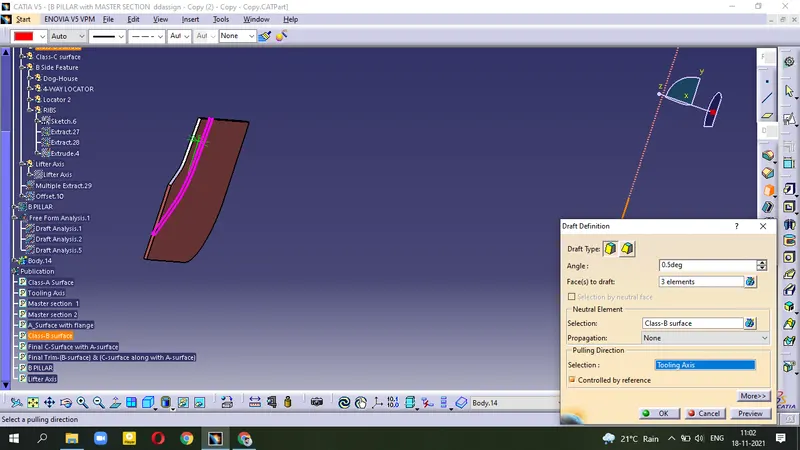
- Use Edge Fillet=0.2mm, Draft angle = 0.5degree
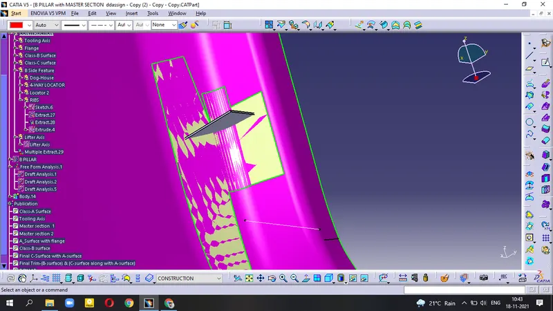
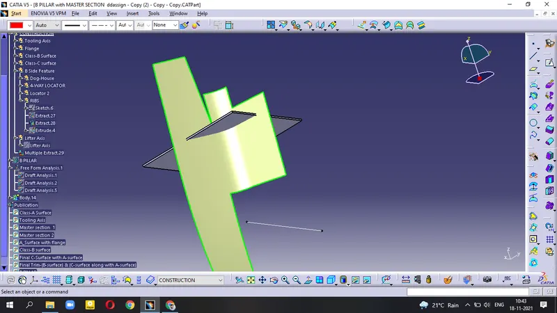
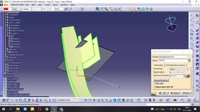
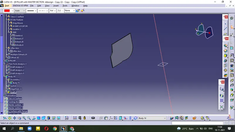
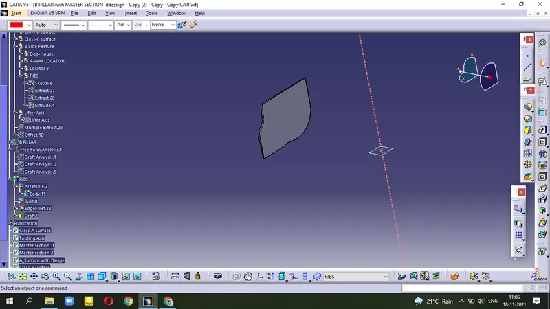
- Insert in New , for boolean operation
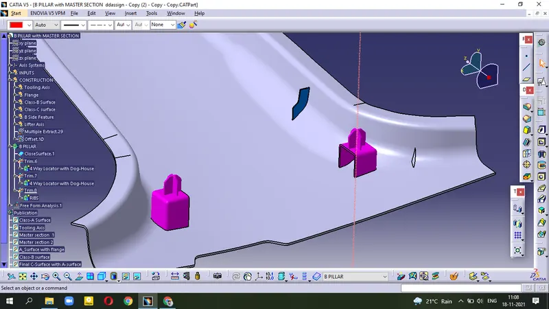
- Union Trim with B-PILLAR
Similarly
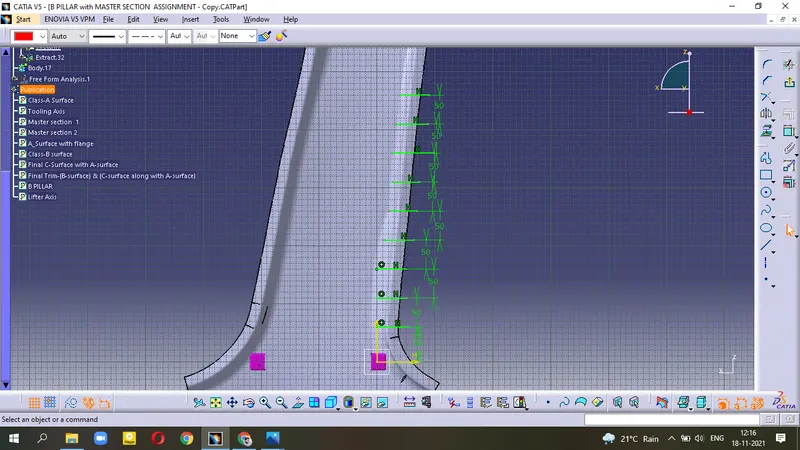
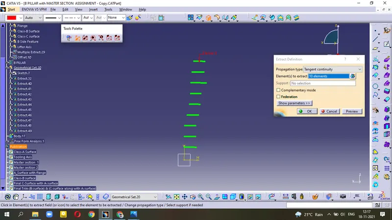
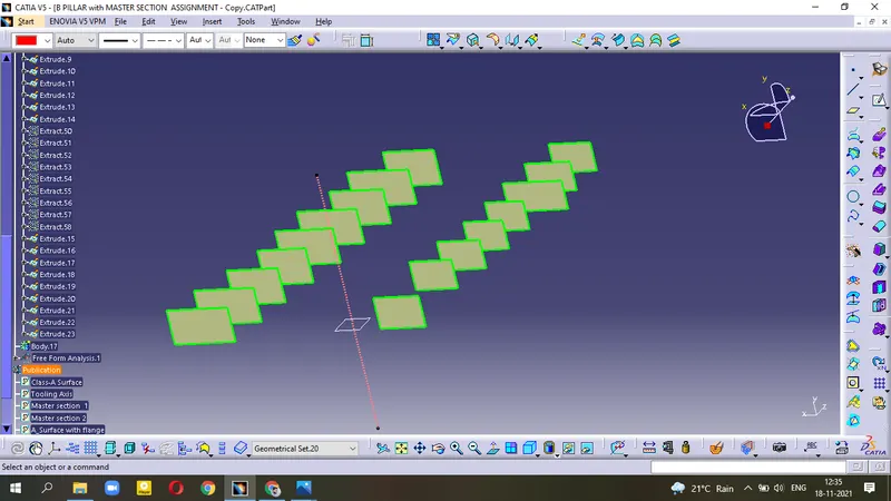
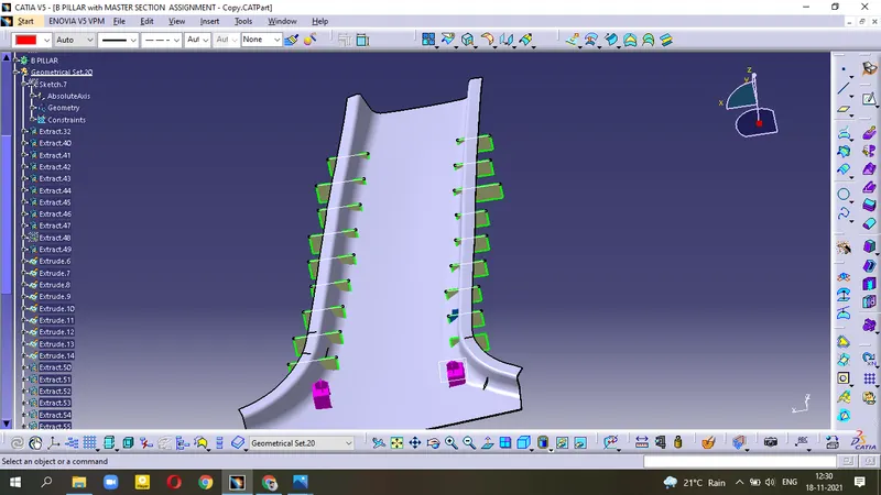
- create more RIBS within B_PILLAR
- Line = 50mm apart - Extract - Extrude - Thick profile - Union Trim = B-PILLAR
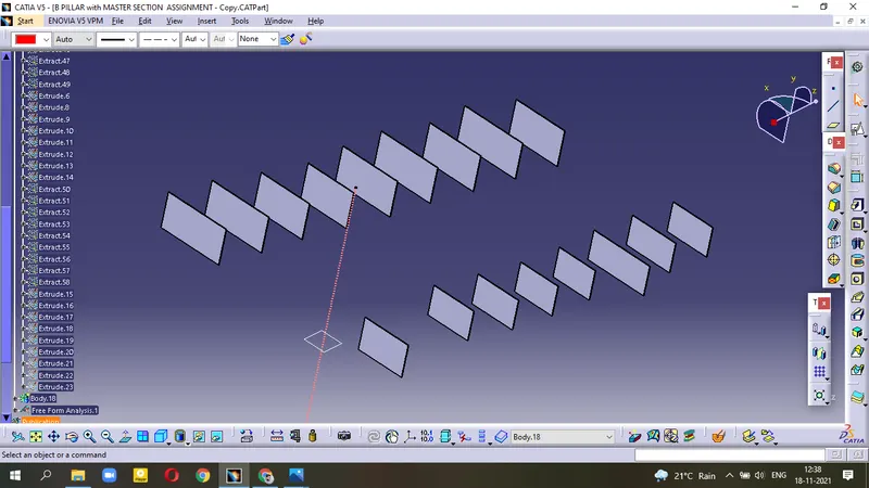
Draft Analysis
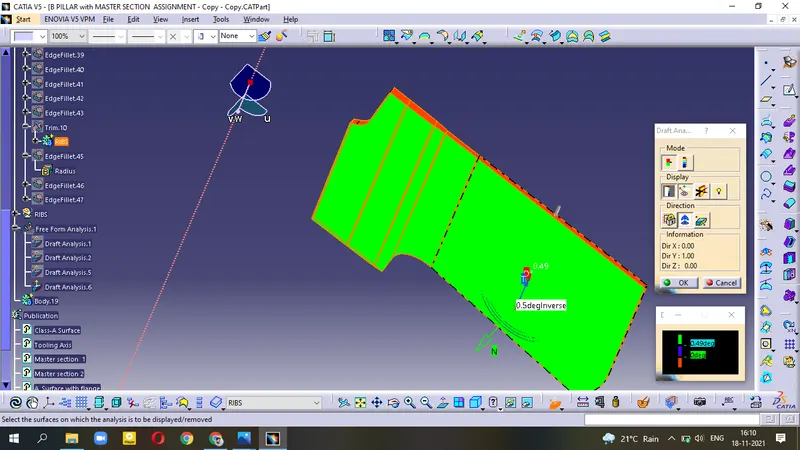
Ribs Draft angle = 0.5mm
- Union Trim with B-PILLAR
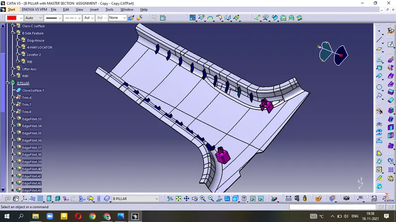
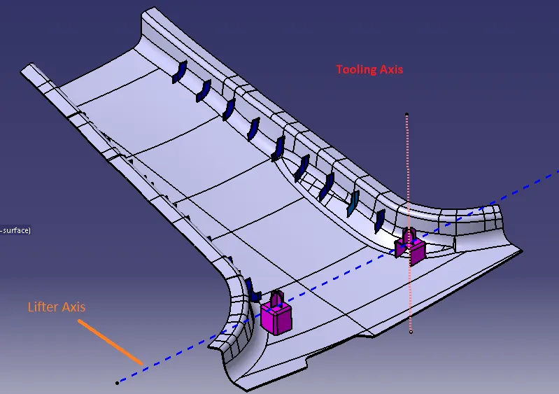
Draft Analysis
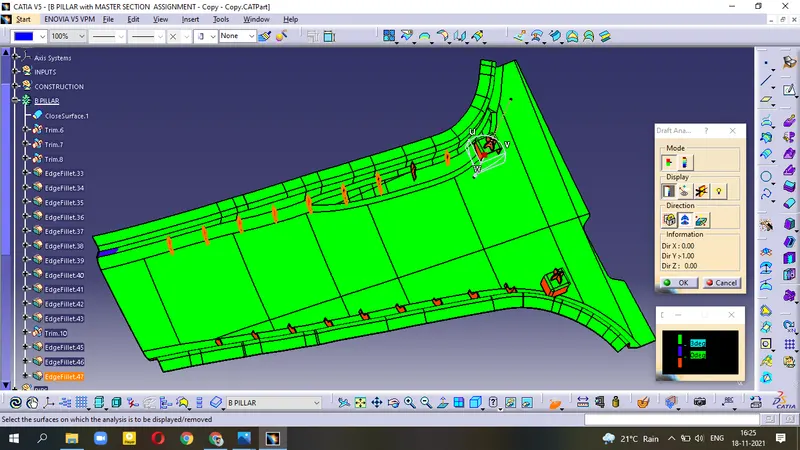
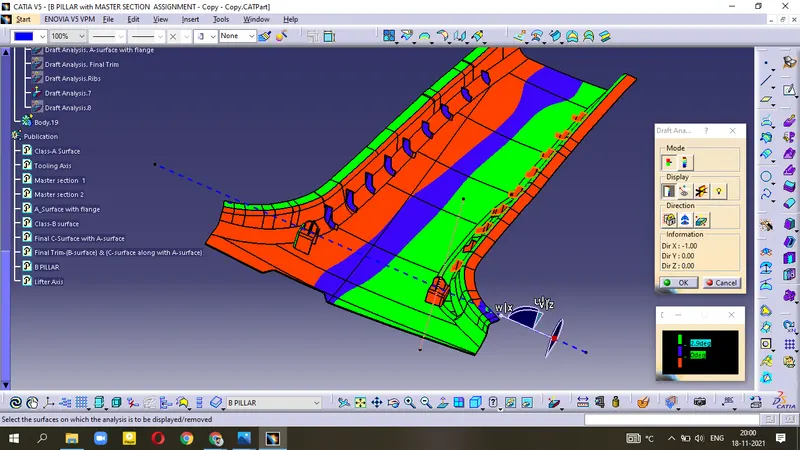
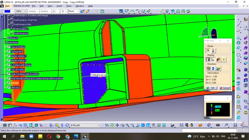
draft angle = 0.5degree
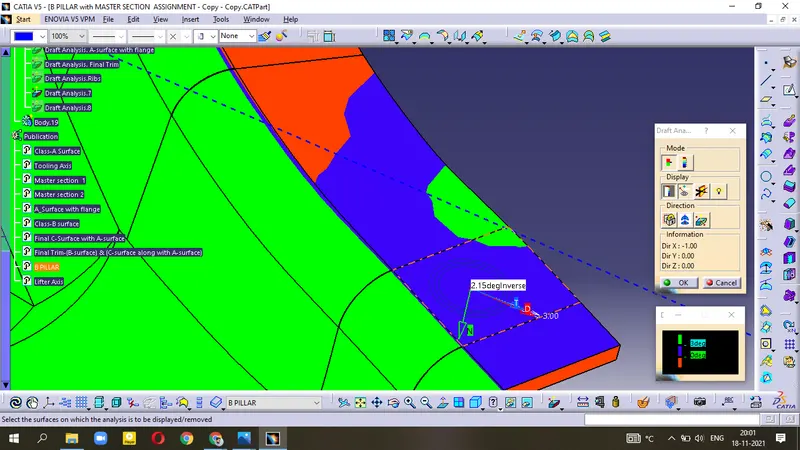
All green faces have Draft = 3degree, Patches have draft = 2.15degree
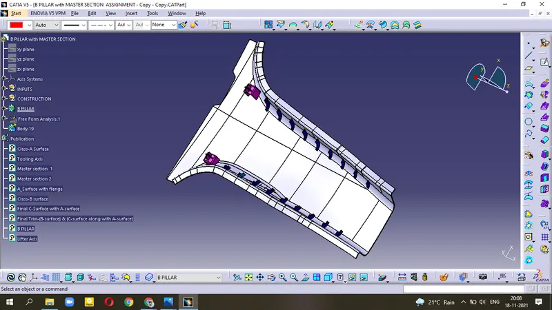
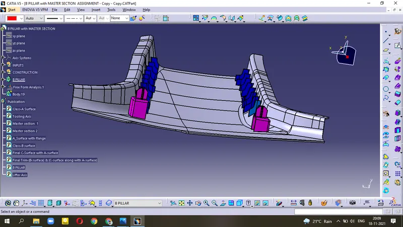
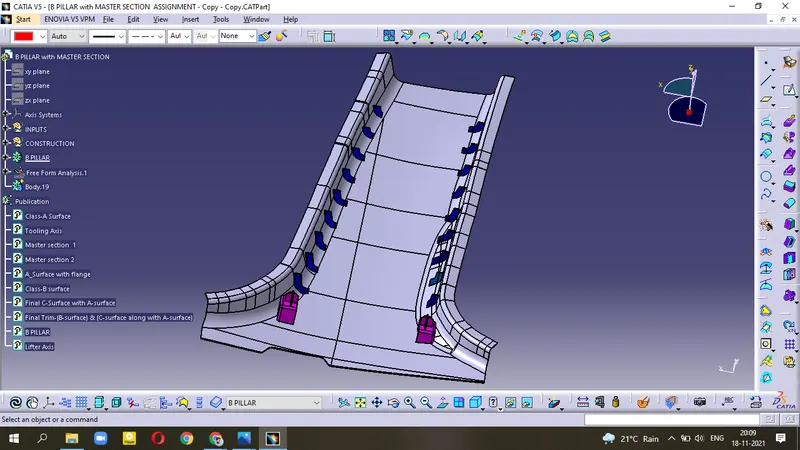
Different view