Week 8 - Challenge 3 - Switch Bezel Design
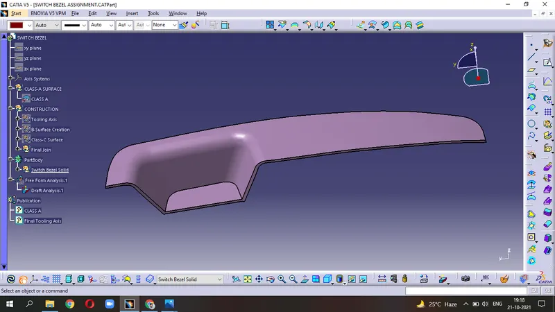
REPORT - Create the Switch Bezel Plastic component through a given Class-A surface :-
Given Class-A surface
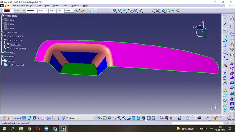
Creation of Tooling Axis :-
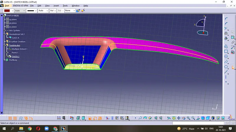
- Since, We apply Intersection method directly when there is four walls present. But from above Class-A surface, there is only 3 walls(Blue). so we can't use intersection directly.
- Use Extract tool to extract the Base surface (yellow) and create the Point in the middle surface.
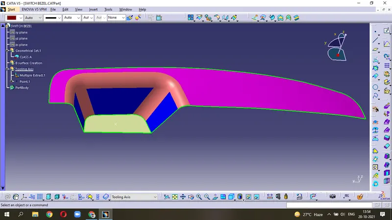
- Create axis on that point to choose appropriate plane axis.
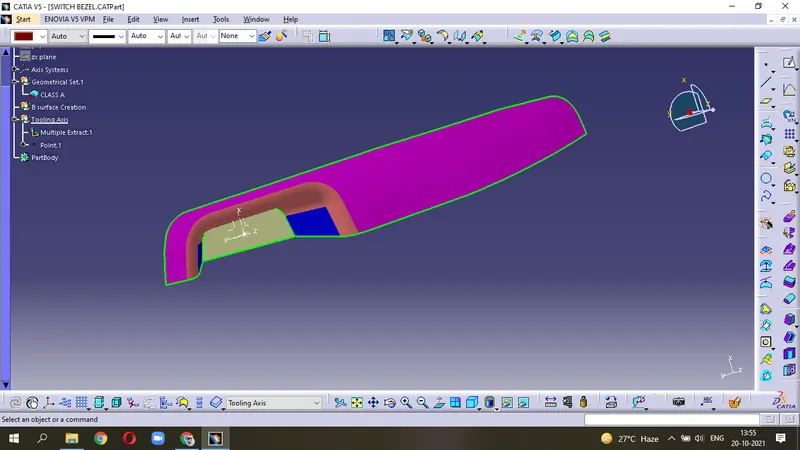
- Goto Positional sketch tool; select the YZ plane and make Intersection on the surafce of Class-A.
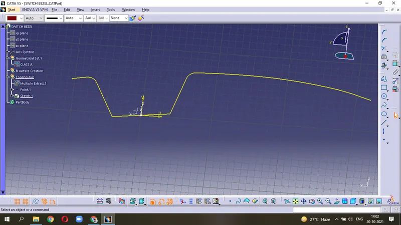
- Create two lines and by using these lines make a Bisecting line which gives the mean line between them. The length of Bisecting line created here is very large so, use trim tool to decrease the length.
- while creating lines, we have to check the Sketch Solving Status .
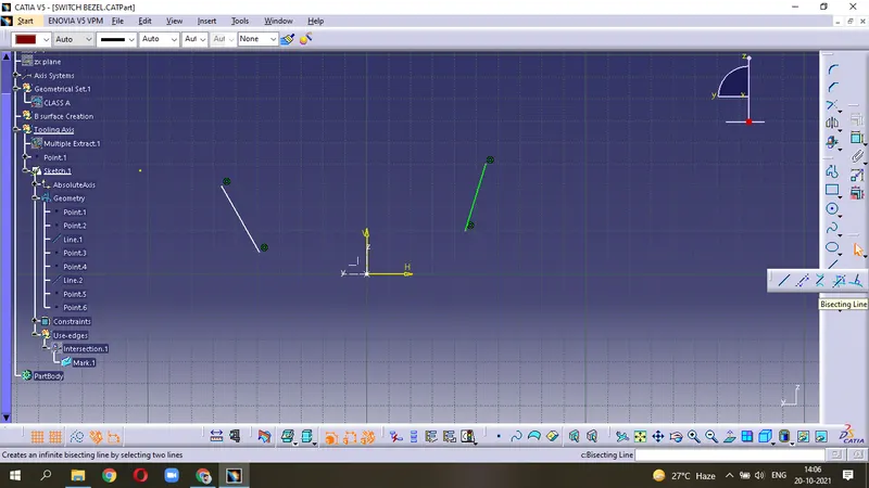
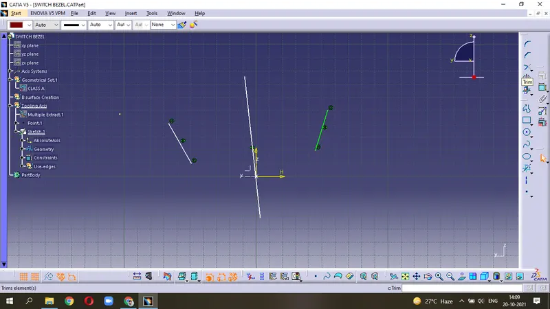
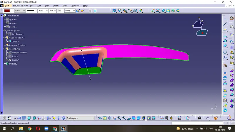
This axis is as Dummy axis which helps us to create our main Tooling Axis .
Similarly,
- Third blue surface; Create Positional sketch in XZ plane.
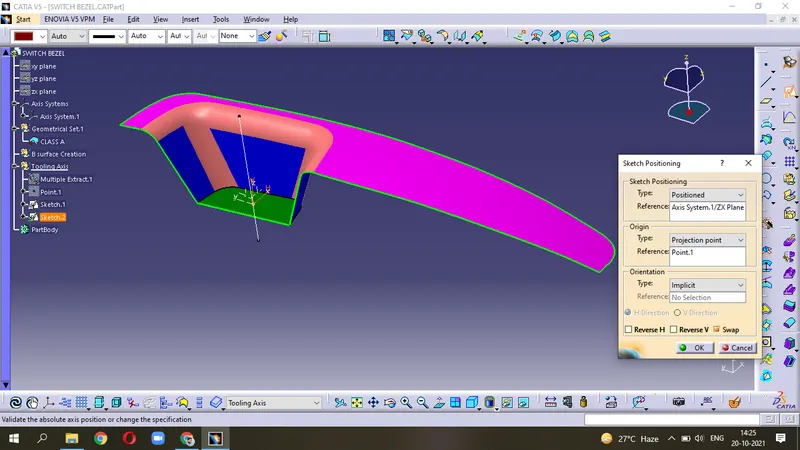
- Intersect with Class-A surface and create the line.
- only one line can be created here & this one should be in exact contact with the intersection line. (if difficulty occurs then use Snap to Point tool)
- Now, we create a line through the point and make the angle= 3degree.
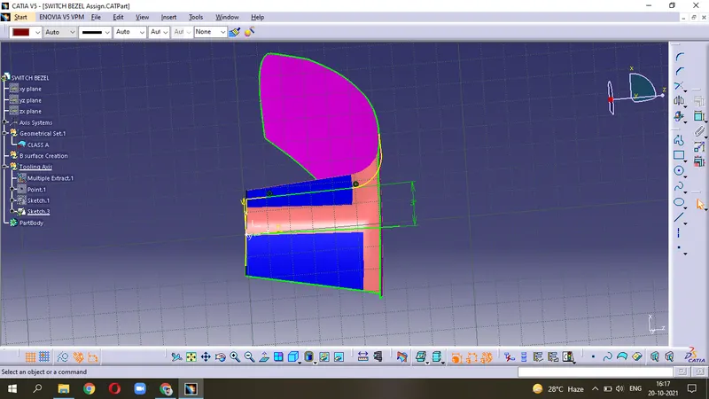
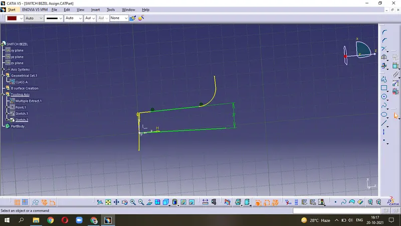
- Use these two lines to make a Bisecting line.
- Now, We have two Dummy axis line.
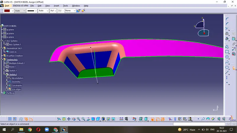
- Bisect these two dummy Axis to get our Final Tooling Axis . It is in Red colour .
- Publish the Final Tooling Axis and Class-A Surface for easy identification .
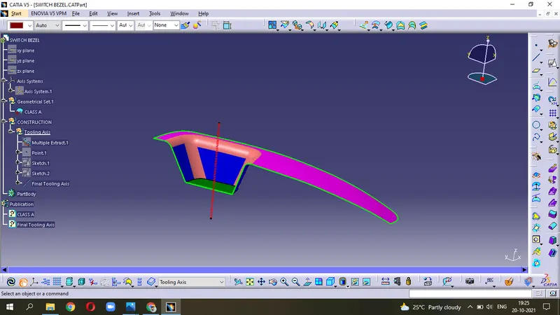
Creation of Class-B Surface :-
(a) Bezel Rest Surface
- Extract Top surface of the Class-A with no propagation
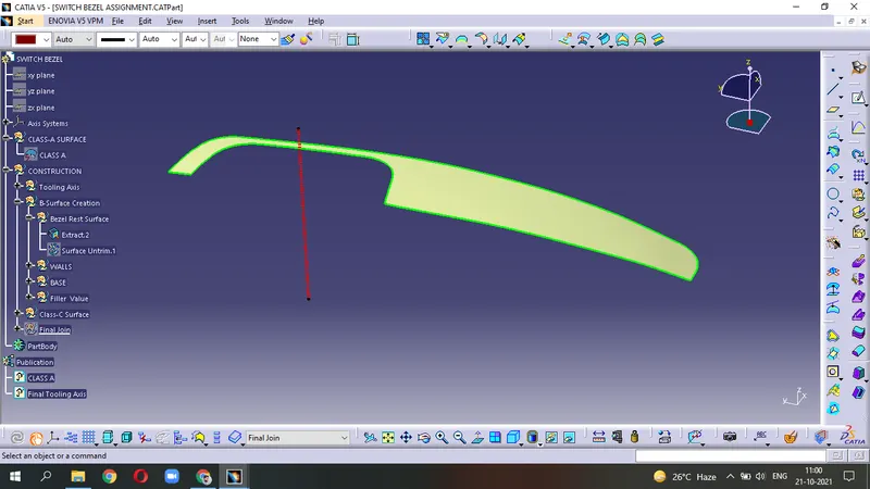
- Untrim the Top surface, It becomes larger .
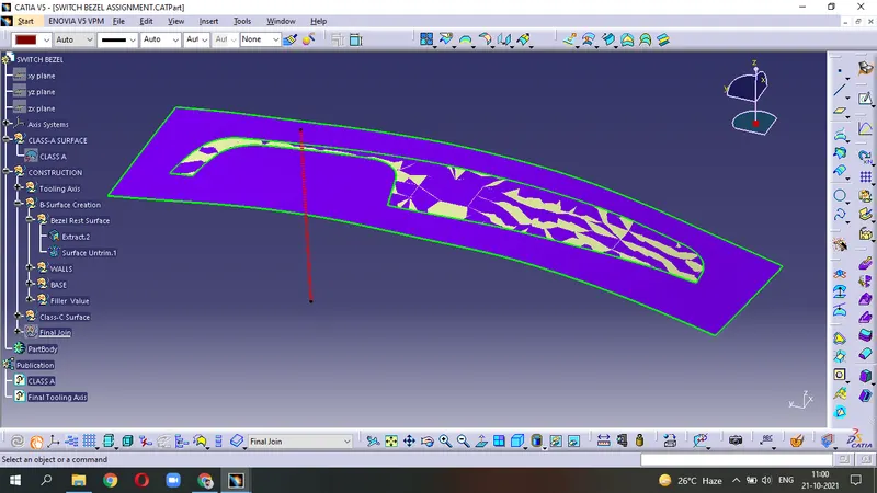
(b) WALLS
- since Fillets are not easily to operate, so we avoid it here .
- Extract three surfaces and then Utrim it .
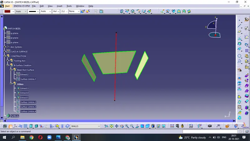
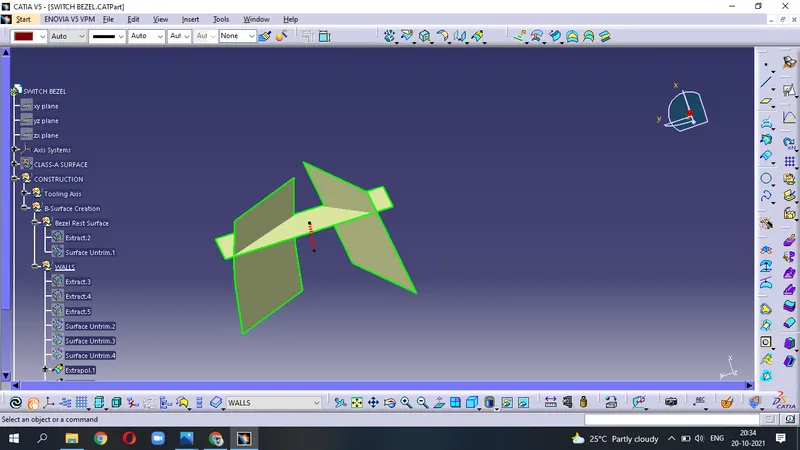
- Extrapolate the surfaces . It becomes larger
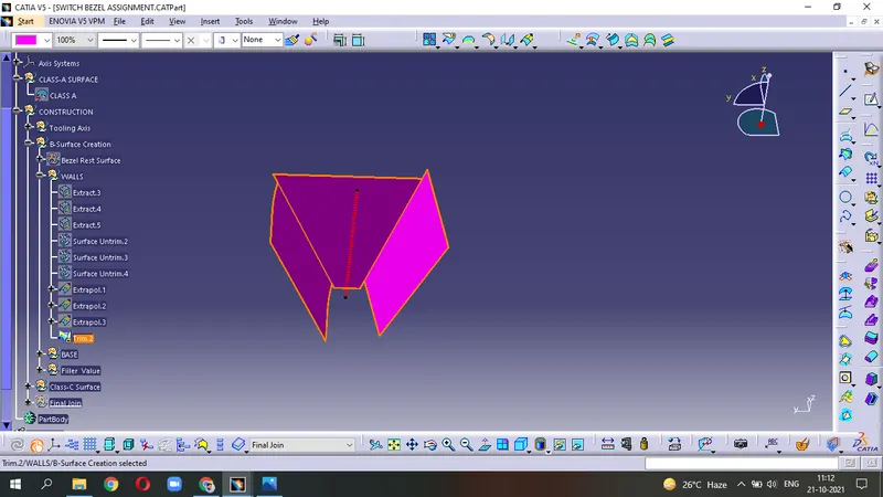
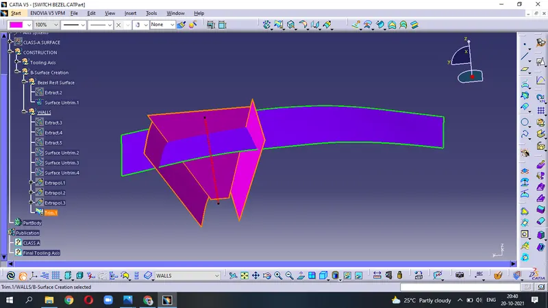
- now, Trim the surfaces .
(c) BASE
- Extract Base surface of Class-A .
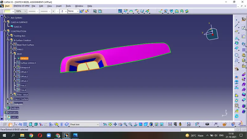
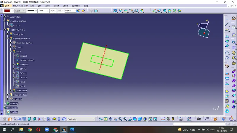
- Untrim the surface then Extrapolate it .
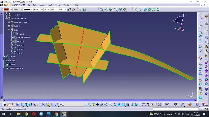
- Now, Offset the WALL trimmed surface, Bezel Surface and BASE surface .
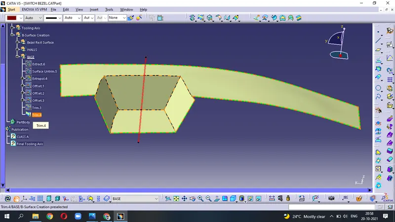
- Trim these surface to get Class-B surface .
- last step of B-surface is to Fillet the edges and also we have to make the Even Wall Thickness to avoid the defects of Flow line after manufacturing .
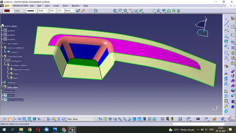
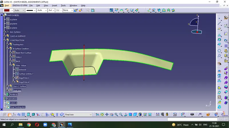
this is our Final B-Surface
B-Surface Tree structure
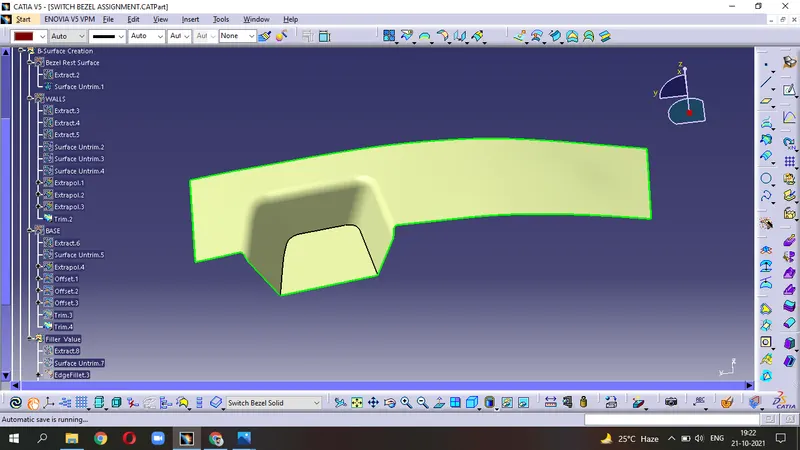
Class-C Surface :-
- Multiple Extract the outer boundary with Tangent Continuity of Class-A surface .
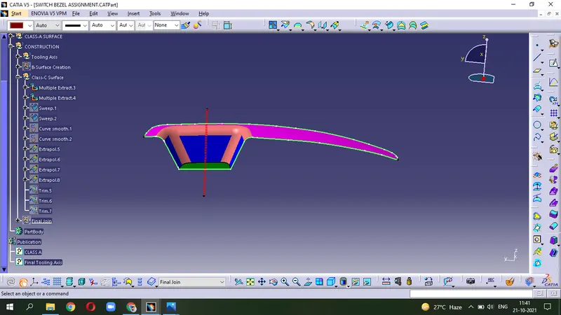
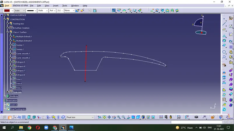
- Sweep both the boundary.
- Remove the patches by applying smooth curve and then replace the Multiple Extract with smooth curve to make surface Smooth .
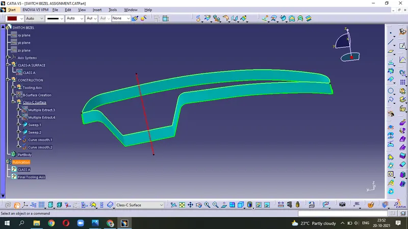
- There is a Gap available between the both surface .
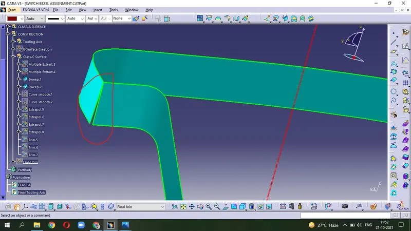
- Apply the Extrapol at 3 mm extension then Trim the surface to get our proper surface .
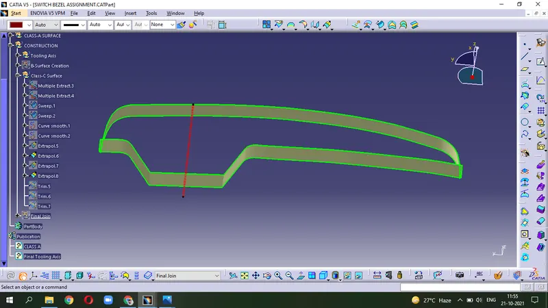
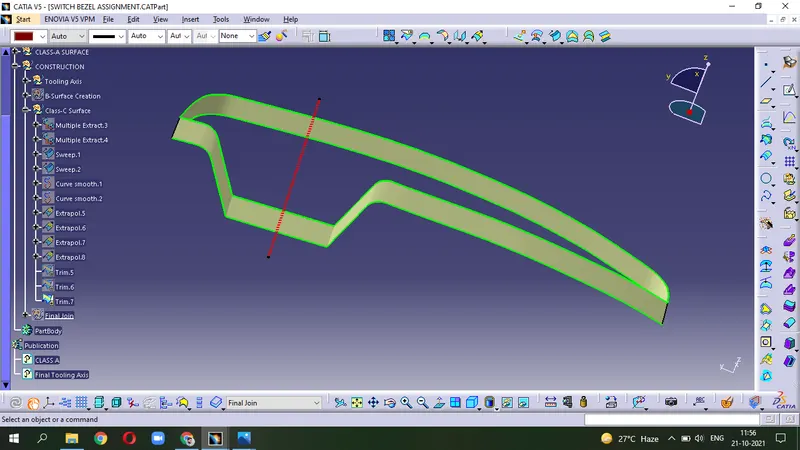
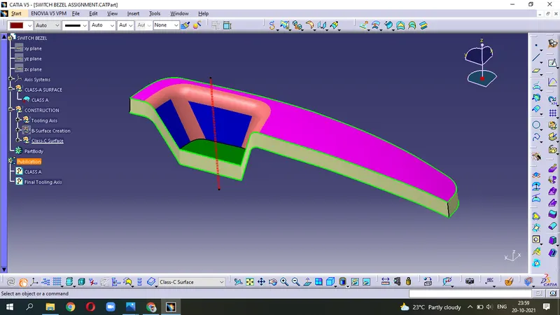
This one is Class-C Surface
C-Surface Tree Structure
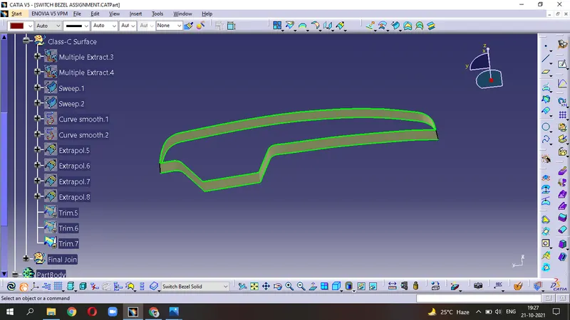
FINAL JOIN :-
- JOIN the Class-A surface and Class-C surface . But we got some discontinuity here.
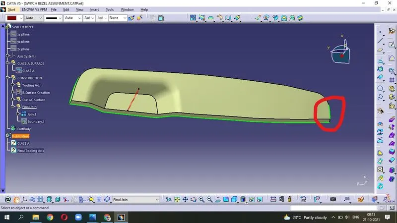
- Rectify this discontinuity by increasing the suface of class-A at very small quantity (ie, 0.05mm) ; and then apply Trim operation .
- (Boundary - Extrapolate - Trim)
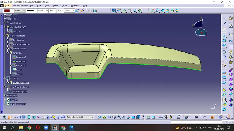
- Trim this surface with our Class-B surface and apply Smooth edges .
- We get the Final Join surface .
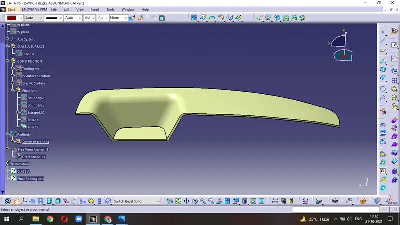
Solid Switch Bezel surface -
- Apply Close Surface into our Final join surface . It gives the Solid surface .
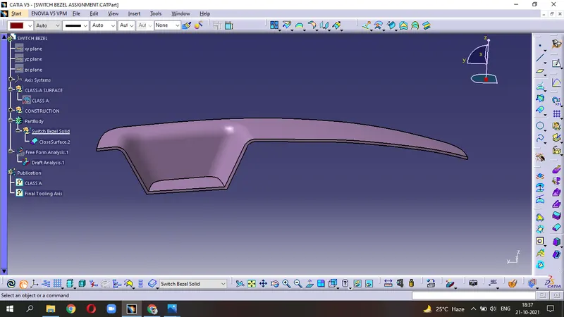
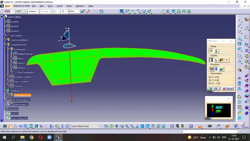
Draft Analysis :-
- Initiate draft Analysis , click on customize view parameter .
- Allign the axis with our main Tooling Axis by using Compass command .
( Note - while clicking on surface, we got a problem ie; whole surface not appears in green colour. It is because of less draft angle = 3degree provided on the Line created while making the second dummy tooling axis. So, we have to increase this draft angle. eg= 5degree )
- after rectification , we get our Final surface which is in green colour .
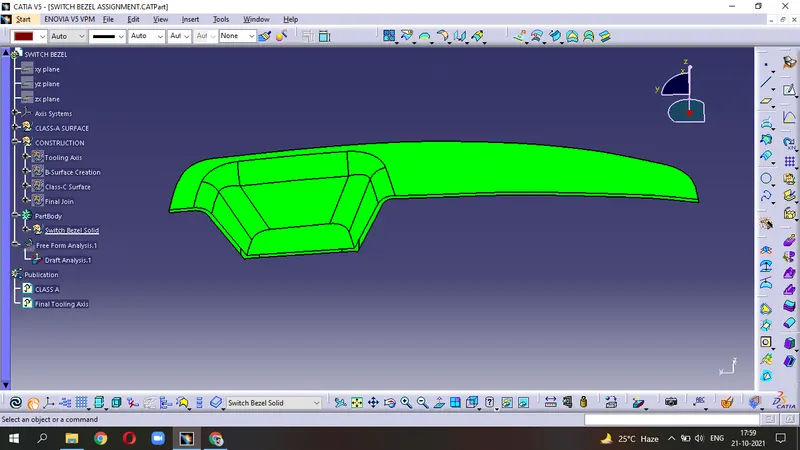
Different View :-
Front view
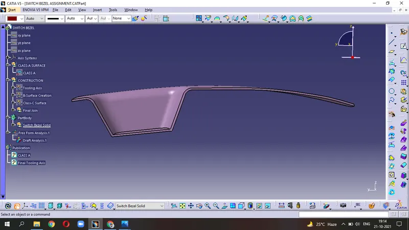
Side view
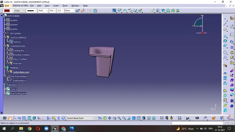
Top view
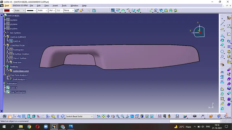
Bottom View
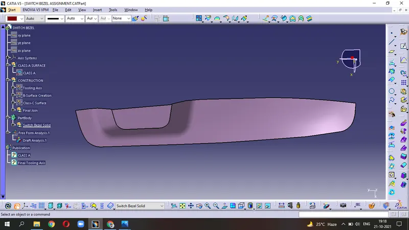
Isometric view