Week 9 - Project - Master Section Development
B-PILLAR MASTER SECTION DEVELOPMENT
OBJECTIVE
- To check the boundary of class A and surface patch.
- To develop class B surface of B-pillar.
- To develop class C surface of B-pillar.
- To develop flanges using master section.
- To develop screw boss, doghouse and locators using master section.
- To develop ribs on class B.
- To develop tooling axis using master section.
- To perform draft analysis.
INTRODUCTION
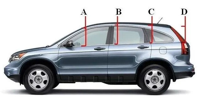
The pillars in cars are supporting structures. They stand vertically and provide good stability and support. Generally a two door sedan has three pillars A, B and C. The shape of pillars resembles alphabets. In this project B-pillar is designed using the master section. The B-pillar provides latch for front door and hinges for rear door. There are some engineering features included in B-pillar for assembly purposes and strength. In this project B-pillar is developed from the given class A surface. The master section is studied to decode the engineering features profile and their dimensional data. Then the B-pillar is developed with locators, screw boss, dog house and ribs as per the design rules. Before start designing the B-pillar the main tooling axis and lifer axis has to be developed using master section.
GIVEN INPUTS
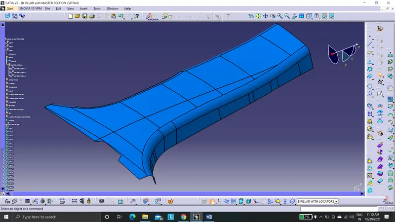
CLASS A
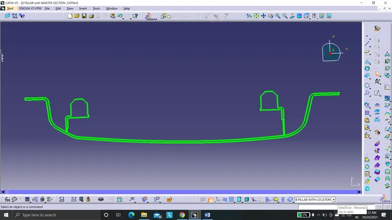
MASTER SECTIONS
1.
2.
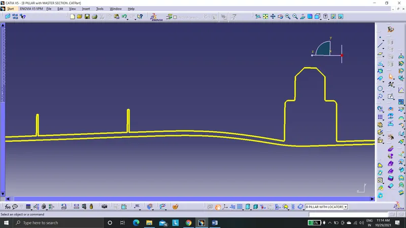
3.
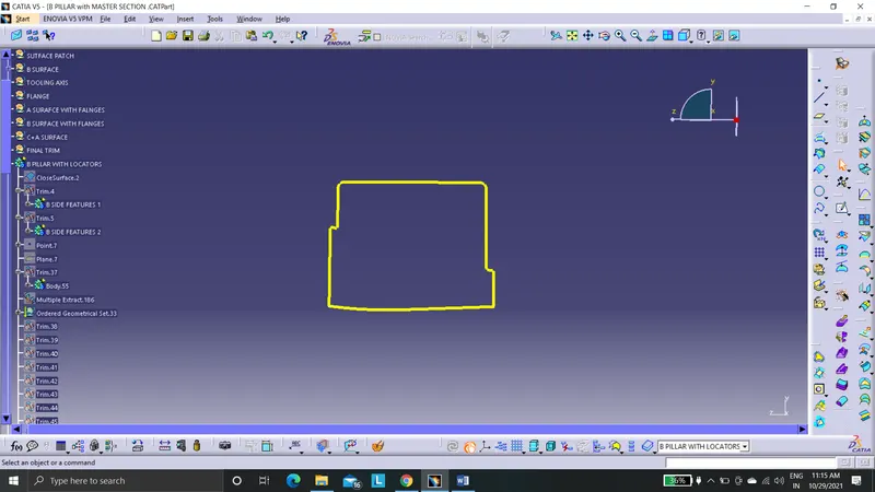
DESIGN FLOW
The design flow is illustrated using tree structure of commands in cad.
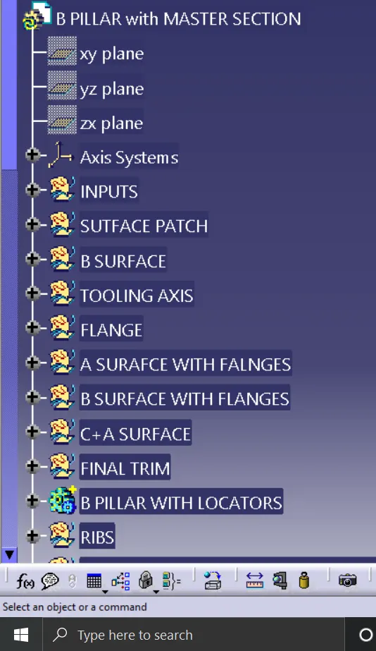
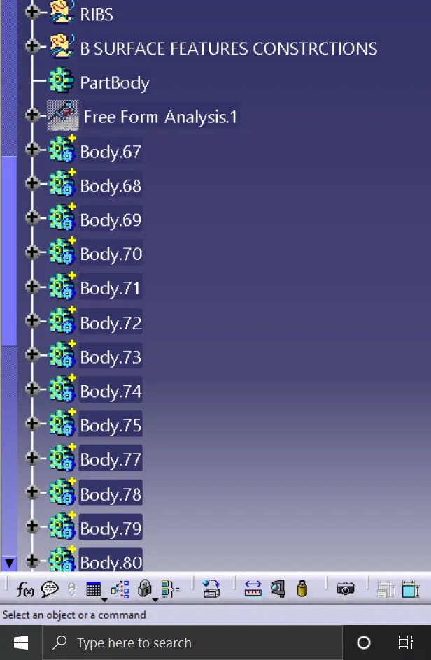
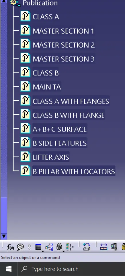
CLASS A BOUNDARY CHECK
The given class A is checked for continuous boundary. There are some discontinuity due to which the surface offset will result in failure of surfaces.
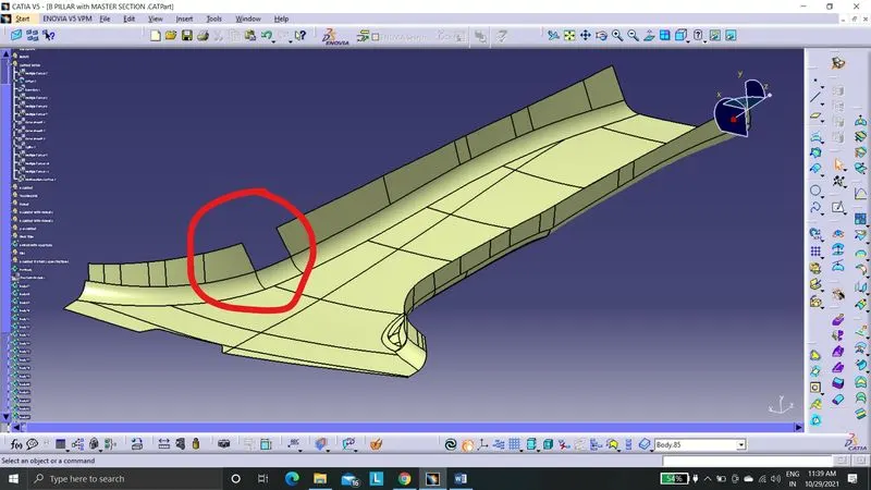
This marked region is failed after surface offset for 2mm. This has to be rectified to develop the class B surface.
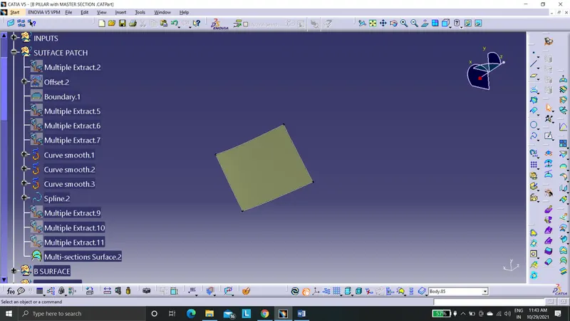
This is the patch up surface for class B.
CLASS B SURFACE
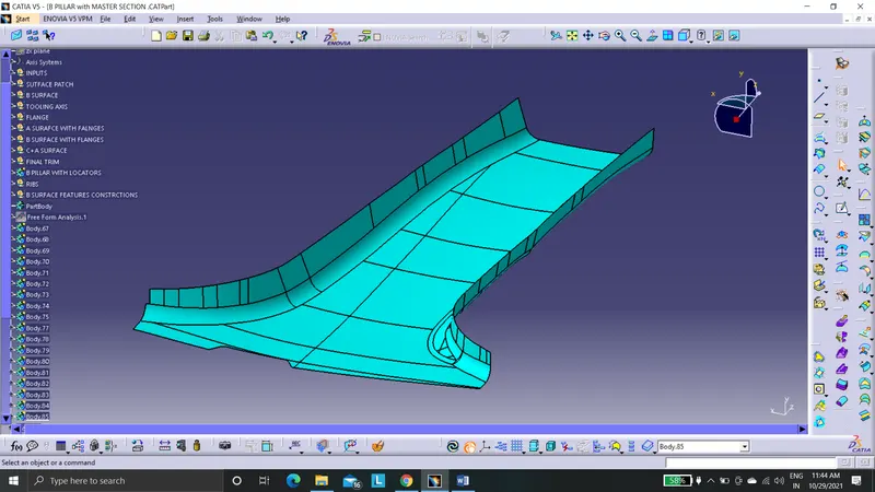
The patch up surface is joined with the class B surface using join command. This give a flawless clas B surface output.
TOOLING AXIS
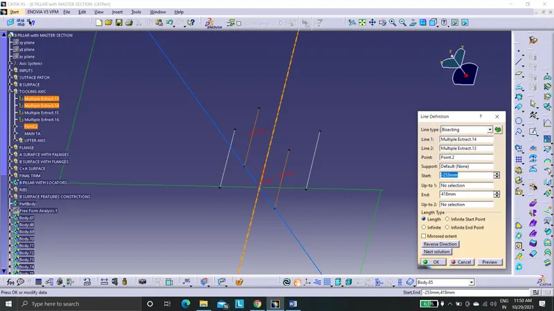
The main tooling axis and lifter tooling axis are developed from the master section. The side surface lines were extracted and a bisecting line is created in tooling direction.
MAIN TOOLING AXIS
LIFTER AXIS
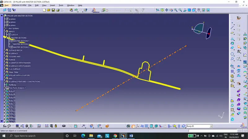
FLANGES
The flanges are there in master section. So we need to create flanges on both side of class A.
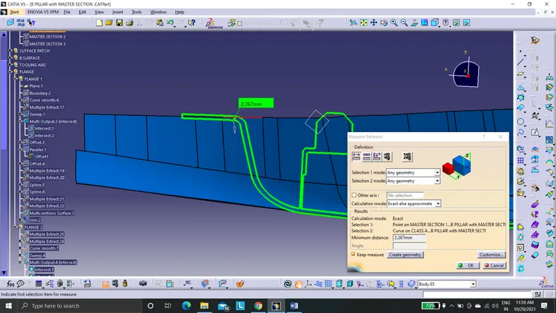
This shows the flanges are approximately 2mm below the given class A edge as inferred from the master section. Therefore flanges 1&2 are created in class A and then it is offset 2mm downside and then trimmed.
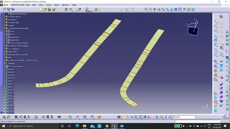
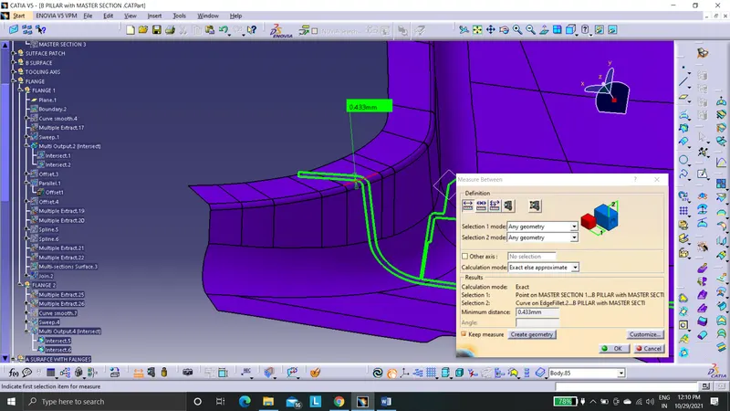
Now the master section flanges are matching with class A.
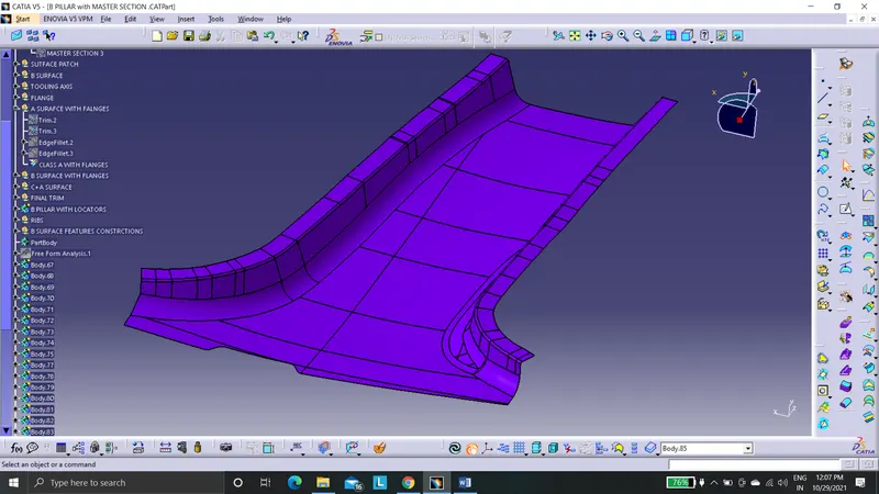
After trimmiing the class A is created with flanges on both sides as per master section.
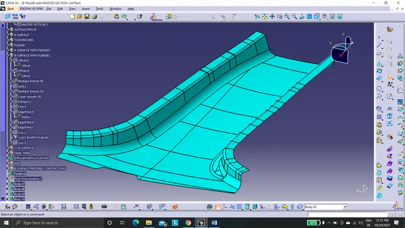
Now in the same way the flanges are trimmed with the class B surface by having an offset of 2mm.
CLASS C SURFACE
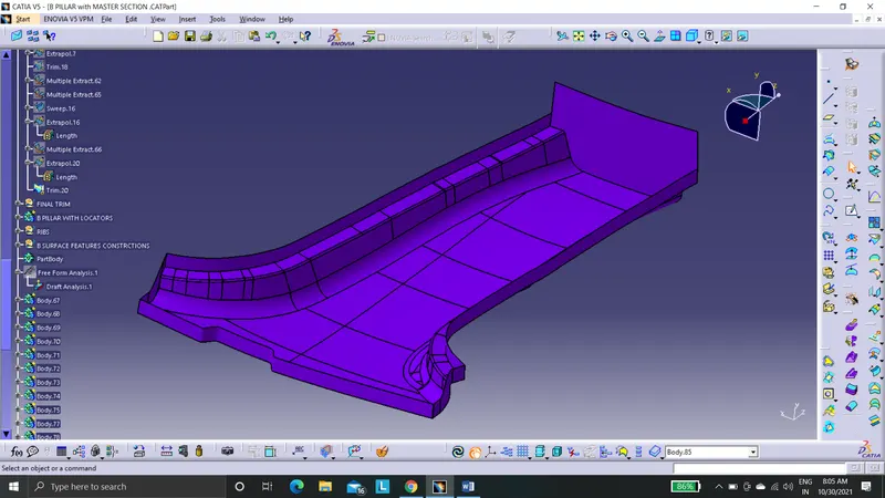
The class C surface is the connecting surface of A and B. Here the boundary of class A is extracted and then it is swept along main tooling axis. Some boundaries will fail while sweep. We can rectify it by extrapolate it. After extending our boundary into surface on both sides of class A we can trim it to form a combined class A and class C.
FINAL TRIMS
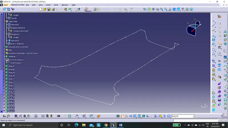
In which the complete surfaces were formed. We have already completed the class A and class C. now we have to combine those two surface with the class B surface. But initially the class B surface doesn’t intersect with class C.
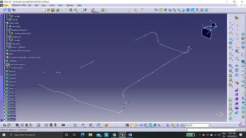
We can see some gaps between class B and class C. So extrapolating it will result in good compatibility for trimming the surfaces together.
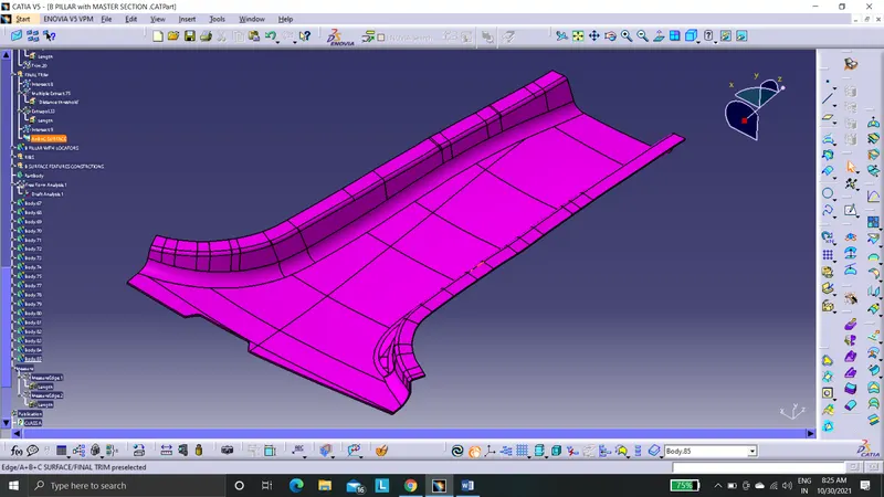
This shows the surfaces were completely intersecting each others. Now we can trim the surfaces which are protruding out of class B surface.
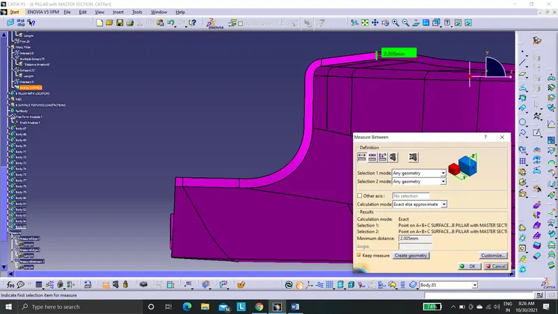
Here we can see the class A and class b surface were seperated at 2mm. Therefore complete class A,B and C surface were created and joined together. Also a closed surface can result in a solid part.
B SIDE FEATURES
In which the engineering features like ribs, dog house and locators were created.
DOG HOUSE
DESIGN RULES
1. THICKNESS (W)
The dog house thickness at the junction with the class B surface should be 0.4 times the main wall thickness or less than that. This slight change in cross section assist in mold filling ability.
W = 0.4 * t mm
2. FILLET RADIUS
Optimal fillet radius is 0.25mm. By smoothening the corners we can reduce presure drop and stress concentration problems.
3. HEIGHT
The height of the contraction in dog house can be 3 to 6mm from B surface. The minimum height of dog house should be 6mm. Less than this height may reduce the strength.
4. WIDTH
The width of the dog house should have a minimal value of 12mm.
For steel width/height ratio is 3:1, prefered ratio is 2:1
5. DRAFT
The minimum draft for boss walls is +/-1.5 degrees.
DOG HOUSE DESIGN
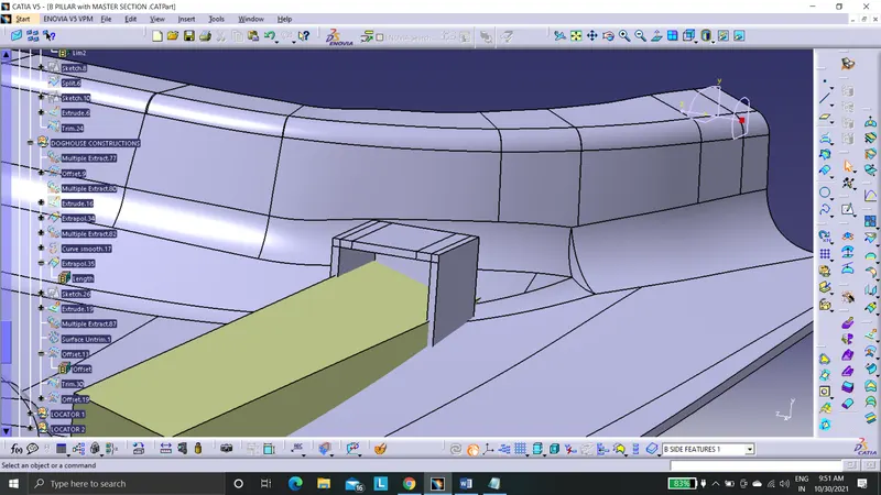
- Sketch the profile as per the master section
- Do surface extrude on it. The minimum specified height is 6mm. So we need to extrude greater than 6mm and also s per the distance in master section.
- Likewise sketch and extrude the limiting surfaces on both sides.
- Use trim command.
- Inset a new body.
- Thicken it.
From design rule,
The thickness at junction of B surface and dog house should be 0.4*t.
Therefore
Thickness at junction = 0.4 * t
= 0.4 * 2.0
= 0.8mm
We can take dog house thickness as 2mm.
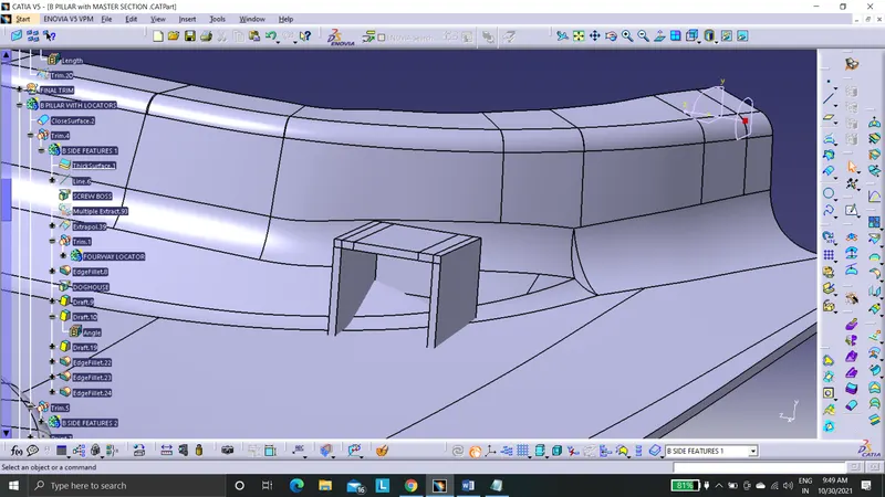
- Create dog house profile and extrude it.
- Trim the solid body.
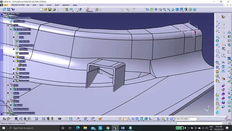
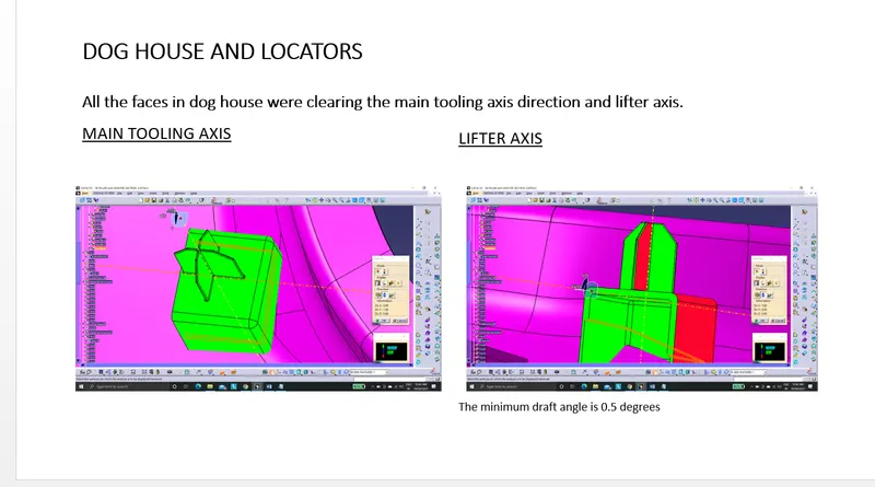
- Draft is given of about 1.5 degrees along lifter axis.
From design rule,
The minimum drat angle for boss is +/- 1.5 degrees.
- All the edges are given 0.25mm maximum fillet radius.
LOCATORS
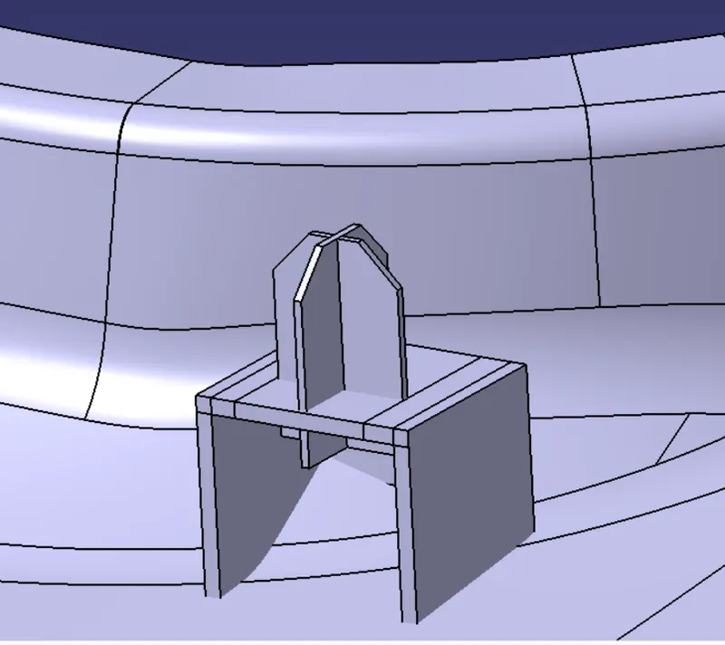
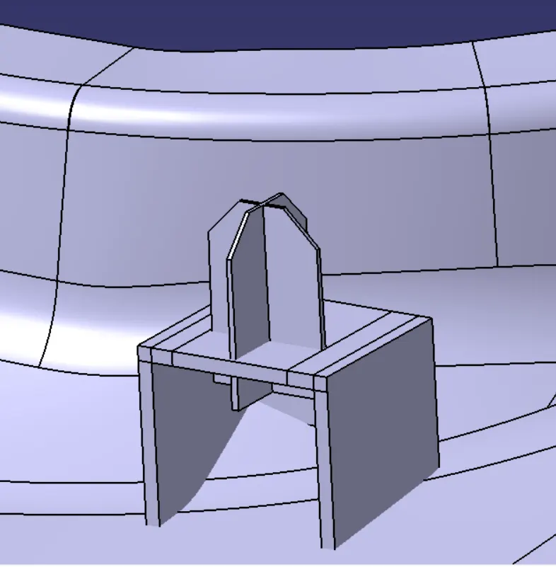
Locators are basically used to restrict movement of mating part and helps in alighning. Locators are like datum. The 3-2-1 principle is used, in which the first datum which we choose arrest 3 degrees of freedom and the second datum arrest 2 degrees of freedom whereas the third arrest last degrees of freedom. By this way all 6 degrees of freedom arrested.\
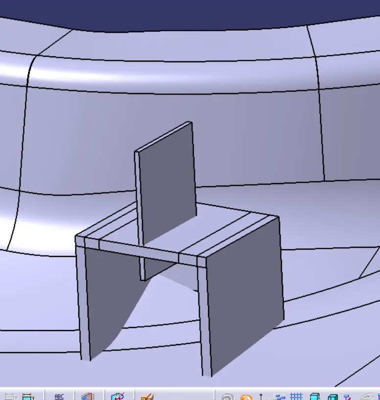
Datum 1 will be a four way locator.
Datum 2 will be a four way locator.
As per the rib design guidelines the four way locator is designed with thickness of 0.8mm. It is given a draft angle of 0.5 degrees. A 3*45 degrees chamfer is given. It is given with a optimal fillet radius of 0.25mm.
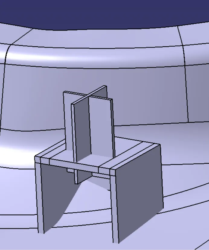
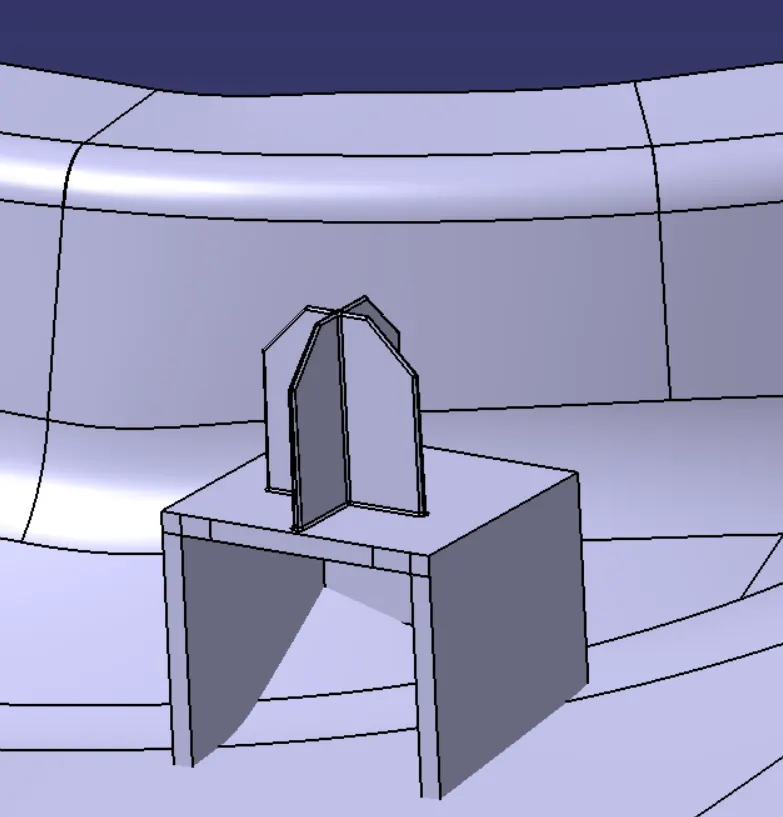
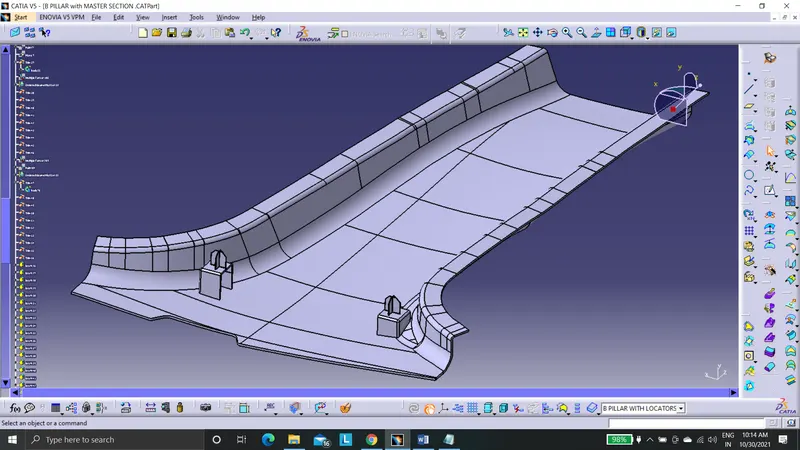
Now we can just copy and symmetry it on the other side for dog house 2 and locator 2 as per the master section.
RIBS DESIGN
Rib is a design feature that helps in strengthening the plastic components. Generally to increase stiffness and strength the component’s thickness is increased. By doing it might end up in sinking, warping, and other defects etc. so instead of increasing the thickness we can add some attachment features to compensate those strength loss. This method much economical. Ribs also facilitates for locating and arresting components in assembly, provides alignment, etc.
RIB DESIGN RULES
1. THICKNESS (W)
Rib thickness at base should be 0.4 or 0.5 times the wall thickness. The minimum tip thickness of rib is 0.75mm. Very thin rib results in poor mold filling ability.
W = 0.4 * t mm
2. FILLET RADIUS
Optimal fillet radius is 0.25mm.
3. HEIGHT
Rib height should be 5 times the wall thickness.
4. ROOT THICKNESS
The root thickness has to be greater than or equal to wall thickness.
4. LOCATION
Ribs can be spaced with each other based on height/width ratio.
3:1 for steel
2:1 is preferred all times.
6. DRAFT
The minimum draft for ribs is 0.5 degrees.
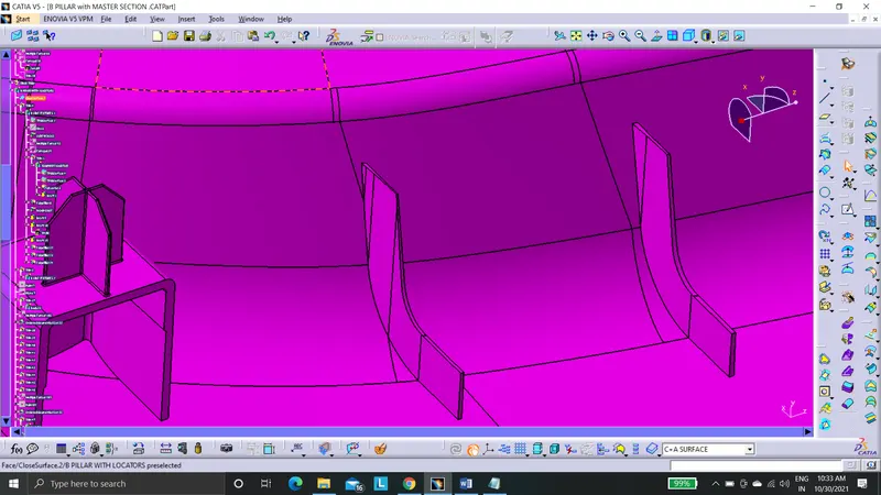
RIB DESIGN
1. Extract the surface on which the rib is to be designed.
2. Draw a line and extrude it to create a surface.
3. Inset a new body
4. Thicken the surface by 1mm.
From design rule,
W = 0.4 * t
= 0.4 * 2
= 0.8mm
6. Change the extruded height to 10mm
From design rule,
H = 5 * t
= 5 * 2
= 10mm
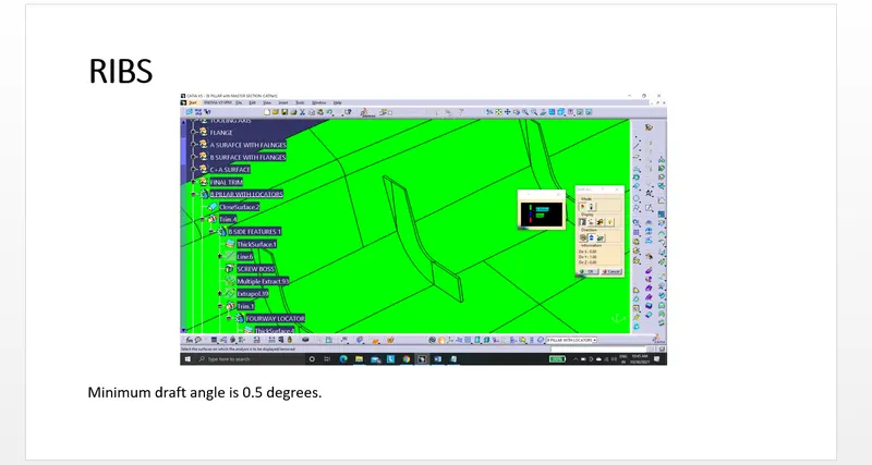
7. Draft is given of about 0.5 degrees.
From design rule,
The minimum drat angle for ribs is +/- 0.5 degrees.
8. All the edges are given 0.25mm maximum fillet radius.
9. Now creating another rib spaced at 50mm.
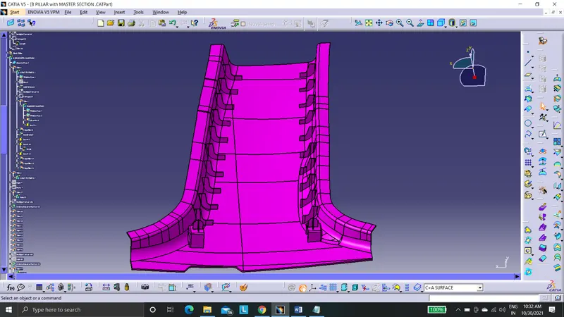
The ribs are copied and translated using point to point method
Therefore the surfaces are designed as per the master section.
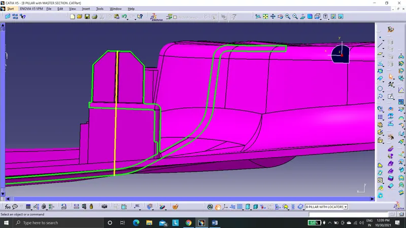
MODELS
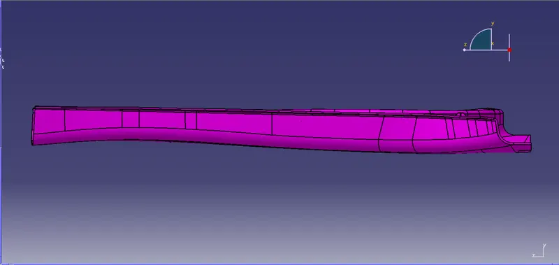
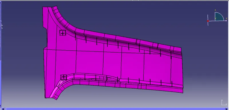
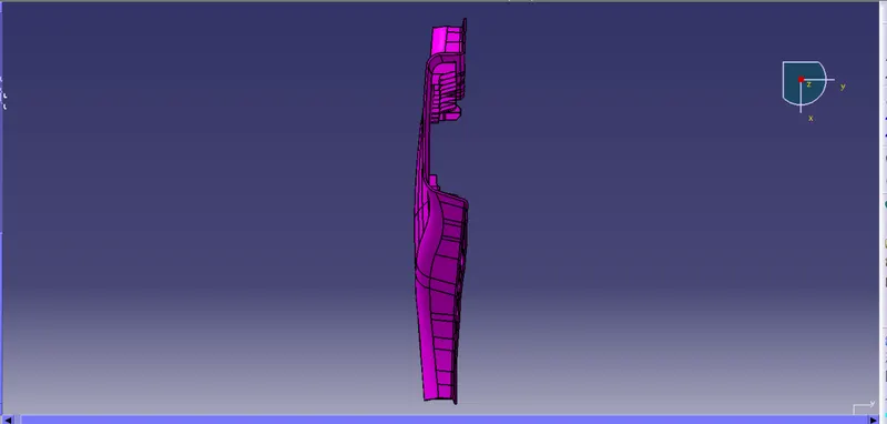
DRAFT ANALYSIS
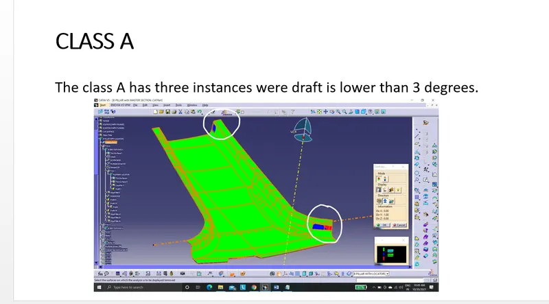
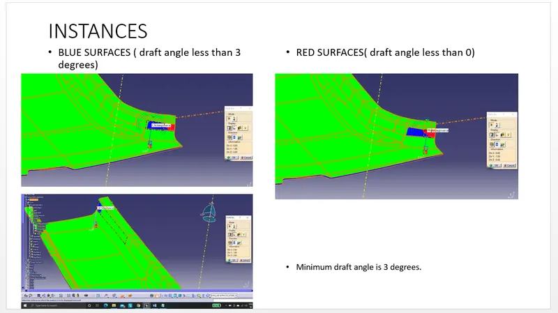
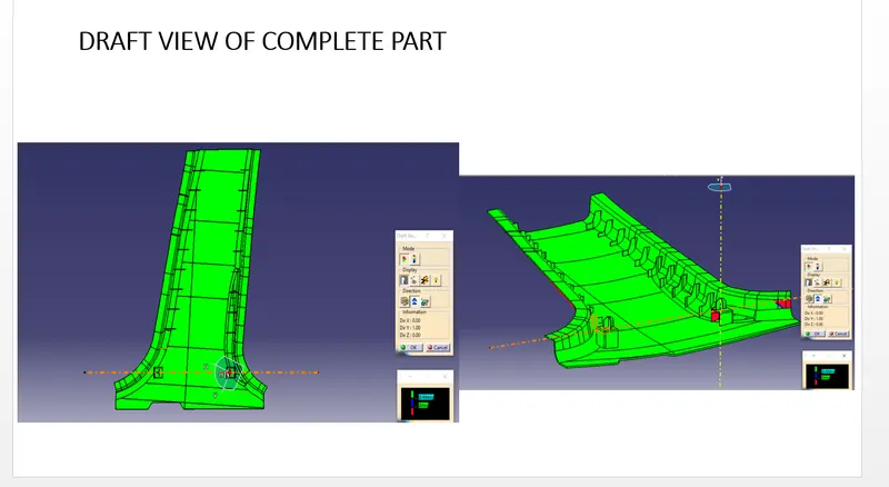
Draft analysis of class A is done with main tooling axis. The limiting draft angle for the class A is 3 degrees. So the green surfaces are clearing in tooling direction. The blue surfaces indicate draft angle less than 3 degrees but greater than 0. Generally it means there is some draft. But the red surfaces are having draft in negative. This will create problem while moulding.
CONCLUSION
Therefore the B-pillar is designed using master section. The complete draft analysis of B-pillar also done.