Advanced Sheet Metal Design Using NX Cad Challenge_1_Casing Design
SHEET METAL DESIGN OF CASING
OBJECTIVES
- To design casing in NX sheet metal.
- To draft the casing.
INTRODUCTION
In this design the casing is designed with the help of basic sheet metal features. It is designed using Siemens NX12.
DEFINING SHEET METAL
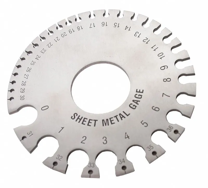
Metallic sheets ranging in thickness value from 0.15mm to 6.35mm were undoubtedly considered as sheet metal. If thickness is lower than the value 0.15mm then it is called foil. If thickness value higher than 6mm than it is called plates. It is measured using the guage, the greater the guage number thinner the sheet metal.
SHEET METAL OPERATIONS
1. SHEARING
2. BLANKING
3.PUNCHING
4.BENDING
5. TRIMMING
6. PARTING
7. SLITTING
8. LANCING
9. NOTCHING
10. PERFORATING
11. NIBBLING
12. EMBOSSING
13. SHAVING
14. DINKING
15. COINING
16. DEEP DRAWING
17. STRETCH FORMING
18. ROLL FORMING
In this casing design mostly bending, cutout and drawing operations are performed.
BENDING
In this process force is applied on the sheet metal and causes them to bend at adesired angle. This operation is performed by the press brake machine. The amount of bend angle depends on depth of bend and punch force given.
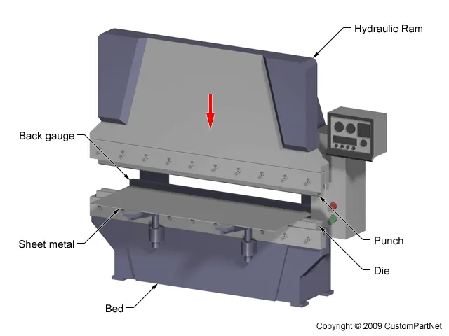
Three main types of bending are
- U-type
- V-type
- Edge bending
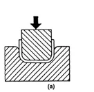
U-type bending
The punch and die both are u shaped and commonly result in u bending.
V-type bending
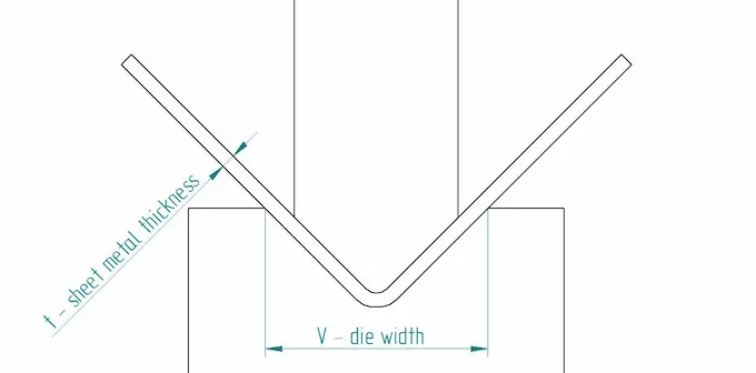
The punch and die are v- shaped. It has three sub groups they were air bending, bottoming and coining.
|
Method/thickness(mm) |
0.5-2.6 |
2.7-8.0 |
8.1-10.0 |
Above 10 |
|
Bottoming(v width) |
6t |
8t |
10t |
12t |
|
Air bending (v width) 12.5t |
|
Coining (v width) 5t |
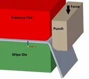
wipe bending
sheet held with wipe die against pressure pad.
Bending force chart
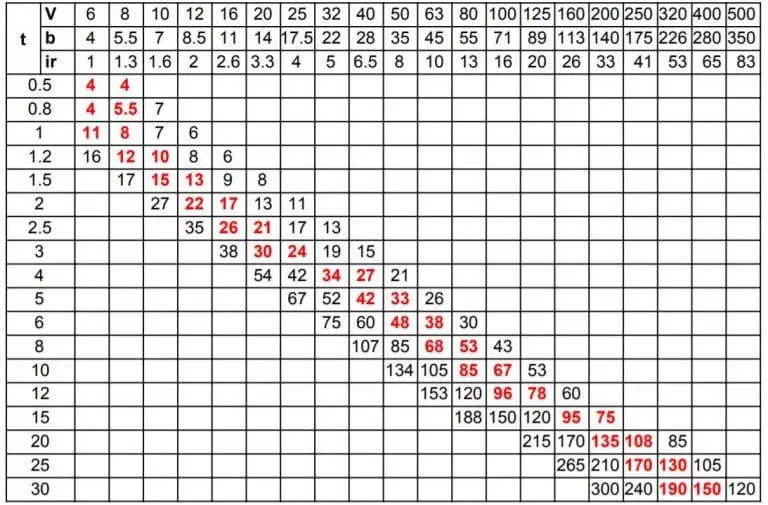
This chart is suitable for construction steel. If wanted to look for aluminium just divide those values by 2. Then for stainless steel multiply the value by 2.
DIMENSION GUIDE
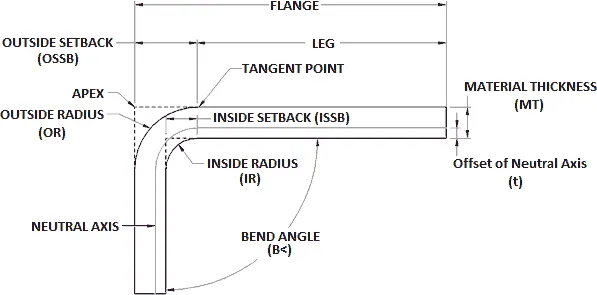
Minimum bend radius - It is recommended that minimum inner bend radius should be at least 1 times material thickness.
Minimum flange length – I can be conveniently note from the bending force chart before tooling. Generally flange lenght must be atleast 4 times the thickness.
Minimum Bend height - H=2t + r
Bend relief – reactangular relief, tear relief and notch relief.
Bend relief prevent the material from tearing.
Bend angle – It has +/- 1 degree tolerence alomg all bends.
Bend allowance – The length of the neutral axis between the bend lines or the arc length of the bend. The bend allowance added to the flange lengths is equal to the total flat length.
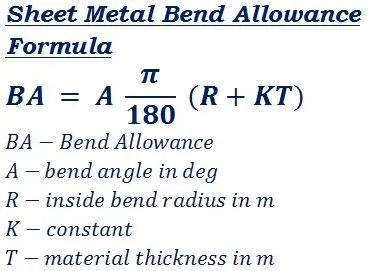
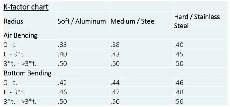
K factor
The K-factor is used to calculate flat patterns because it is related to how much material is stretched during bending.

PROCESS FLOW
Sketch – origin centered rectangle-length=60mm, width=50mm
preferences-sheet metal-global parameters=1mm
Tab=1mm thickness
Normal cutout-sketch-left edge coincident rectangle-5mm wide, 40mm long
Bend -sketch-two symmetrical horizontal line 10mm from the upper left corner-bend angle=90 degree
Flange-selecting inner edges in top, outer egdes in bottom
Break corner-method-blend,radius=1mm
unbend-selecting main face as stationary face and one of its adjecent face as bend face
Feature-Hole-select points created in the flanges at midpoint, type-screw clearence,
screw size=M2,fit=H13
Dimple-sketch 5mm length each half side centered at (0,0,0)
Studio spline-select all the 16 corners
Move curve-select spline,Motion -angle,Angle=45 degree
Dimple-1mm depth,side walls- materials inside,rounding field=1mm
sketch-xy plane-5mm dia,8mm each from corners
Bead-select sketch,depth=1mm,radius=1mm
Rebend-select faces in reverse order
Flat pattern-select central sheet face and validate,visible in model views
Drafting- A4 size sheet,view-select flat pattern,sca
TOOLS AND FEATURES USED ON SHEETMETAL TO DESIGN CASING
- Sketch
- Tab
- Cutout
- Bend
- Flange
- Break corner
- Unbend
- Hole
- Studio spline
- Move curve
- Dimple
- Bead
- Re bend
- Drafting
- Base view
TOOL AND FEATURE DESCRIPTION
- SKETCH
It is a 2d representation of a 3d part. It includes entities like line, rectangle, spline, circle, etc. It is a predetermined drawing with dimensions and relations.
- TAB
It is the base part for any sheet metal design. Flanges can be made only from the tab edges.
- CUTOUT
This command is to remove the desired shape of material. Removal sketch can be drawn on the sheet metal face, wherever required.
- BEND
It is to bend the tab/flange by creating the line sketch. The bend can be like U, v or channel shape.
- FLANGE
It is created with one or more edges at specified location. The minimum flange length must be atleast four times the thickness of the sheet metal. Bend radius is equal to the sheet metal thickness.
- BREAK CORNER
This command gives a smooth finish over the corners of the sheet metal part.
- UNBEND
It makes the part unbend, that is all the features done are made flat. This is useful while sketching on the corners and bend areas.
- HOLE
This feature is to put a hole on the part. There were screw type hole with specified scre size and fit.
- STUDIO SPLINE
It results in a set of splines after selecting the points for its path. It is used for making splines along the sketch.
- MOVE CURVE
It moves or rotates your curve.
- DIMPLE
It rises a drawn sketch from the base plate. This command doesn’t save material instead it maintains the rigidity.
- BEAD
It lifts material along contour sketch.
- REBEND
This command puts back all the bends already created also along with new features included while in unbent state.
- FLAT PATTERN
It is done before drafting. It gives a flattened version of the sheet metal part.
- DRAFTING
This command is to have 2D drawing of the sheet metal part created.
- BASE VIEW
It specifies the location, orientation, view and scale of the part for drafting.
CASING IMAGES
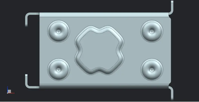
FRONT VIEW
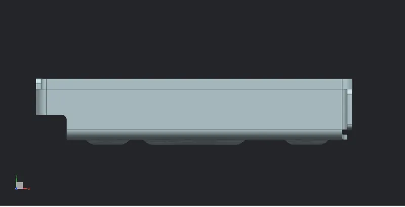
SIDE VIEW

TOP VIEW
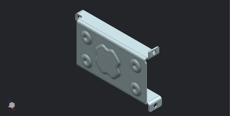
ISOMETRIC VIEW
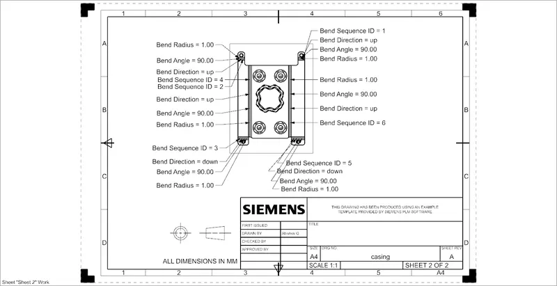
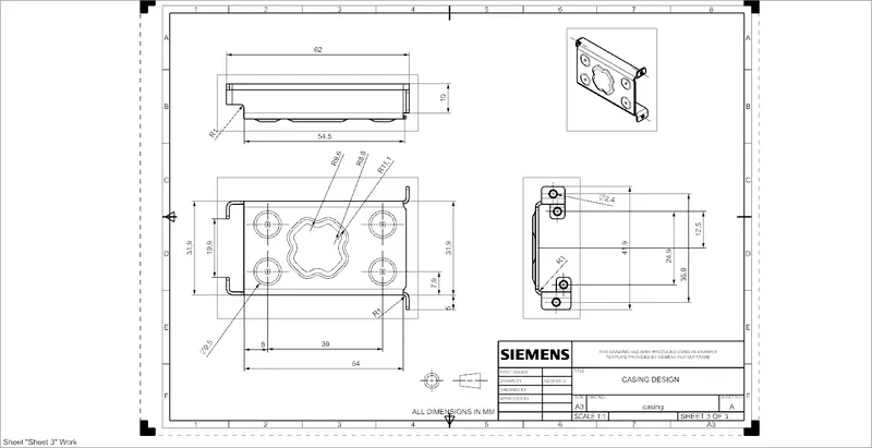
DRAFTING
Creating a new draft on A4 size sheet of flat pattern#1.
CONCLUSION
The casing sheet metal part is created using NX12 software.