Advanced Sheet Metal Design Using NX Cad Challenge_2_Box Assembly
SHEET METAL DESIGN OF BOX ASSEMBLY
OBJECTIVES
- To design box assembly in NX sheet metal.
- To draft the box assembly in A4 sheet.
INTRODUCTION
In this design the box assembly is designed with the help of basic sheet metal features. It is designed using Siemens NX12.
HEMMING
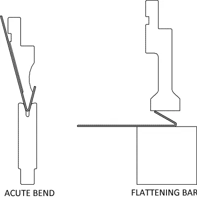
Hems are folds at the end of a part to create a rounded edge. Hemming is a forming operation in which the edges of the sheet are folded or folded over another part in order to achieve a tight fit. Normally hemming operations are used to connect parts together, to improve the appearance of a part and to reinforce part edges. Hemming is used in assembly as a secondary operation after deep drawing, trimming and flanging operations to join two sheet metal parts (outer and inner) together.
There are two types of hemmed edges
1. closed hem
2. open hem
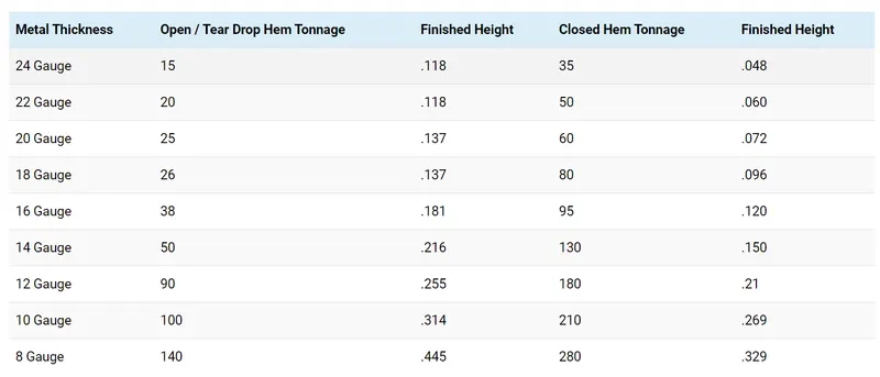
Closed hems are completely flush while open hems have an air pocket in the bend. The major difference is that the tonnage required for a closed hem is much greater than that for an open hem.

1. For tear drop hems, the inside diameter should be equal to the material thickness.
2. For open hem the bend will lose its roundness when the inside diameter is greater than the sheet metal thickness.
3. For bends, the minimum distance between the inside edge of the bend and the outside of the hem should be 5 times material thickness plus bend radius plus hem radius.
TONNAGE CHART FOR HEMMING
DIMPLE
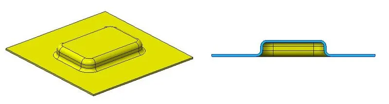
This is a feature that gives a shallow depth of a required shape of sketch. It is manufactured by drawing the sheet metal which comes under forming operation. During this operation, stretching is the main deformation mode resulting in high tension. Thereby the metal is subject to excessive thinning or fracturing. Consequently the depth of embossments like these have reastrictions. It is recommended that the maximum depth of dimpling can be less than or equal to three times the thickness.
PROCESS FLOW
TAB - 200*150,1mm thickness
FLANGE - 2no’s in 200mm edge, 2no’s in the closing side
CLOSED CORNER - on the adjacent sides of the flanges.
FLANGE – 6.5mm in the closing side of box with bend radius 0.5mm.
HEM – open ended hem with bend radius 0.5mm.
MIRROR – mirror the sheet metal part about its mid plane.
UNITE – convert this two parts into single part.
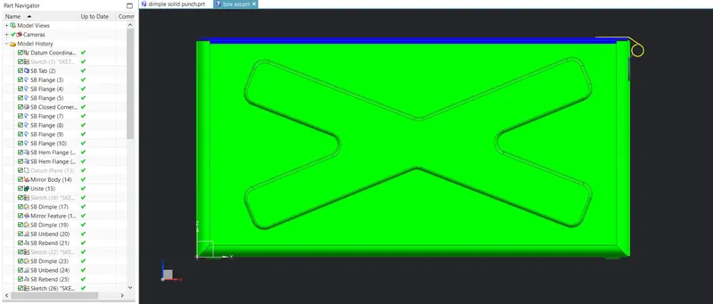
DIMPLE – raise the x shaped figure for depth of 2mm.
MIRROR – mirror the dimple created.
DIMPLE – raise the rectangular sketch for the depth of 2mm.
UNBEND AND REBEND
BEAD – circular bead – radius 2mm, depth 2mm.
MIRROR FEATURE
HEM – closed hem of bend outside.
TAB – lid for the box of thickness 2mm.
FLANGE – closing flange on the top lid.
TAB - rectangular tab of thickness 1mm.
BREAK CORNER – radius 10mm.
FLANGE - straight and inclined flange.
HEM – open loop of 325 degrees.
UNBEND
NORMAL CUTOUT
REBEND
MIRROR BODY
TAB – rectangular tab of 1mm thickness.
BREAK CORNER – radius 10mm.
FLANGE – 13mm length, 40 degrees.
HEM – open loop 325 degrees.
NORMAL CUTOUT
APPEARENCES
DRAFTING
TOOLS AND FEATURES USED ON SHEETMETAL TO DESIGN BOX ASSEMBLY
- Sketch
- Tab
- Normal Cutout
- Closed corner
- Flange
- Break corner
- Unbend
- Unite
- Hem
- Dimple
- Bead
- Re bend
- Flat pattern
- Drafting
- Base view
TOOL AND FEATURE DESCRIPTION
- SKETCH
It is a 2d representation of a 3d part. It includes entities like line, rectangle, spline, circle, etc. It is a predetermined drawing with dimensions and relations.
- TAB
It is the base part for any sheet metal design. Flanges can be made only from the tab edges.
- NORMAL CUTOUT
This command is to remove the desired shape of material. Removal sketch can be drawn on the sheet metal face, wherever required.
- CLOSED CORNER
It is used to close the edges of the flanges created.
- FLANGE
It is created with one or more edges at specified location. The minimum flange length must be atleast four times the thickness of the sheet metal. Bend radius is equal to the sheet metal thickness.
- BREAK CORNER
This command gives a smooth finish over the corners of the sheet metal part.
- UNBEND
It makes the part unbend, that is all the features done are made flat. This is useful while sketching on the corners and bend areas.
- UNITE
This feature is to combine two sheet metal parts into a single body.
- HEM
It is used for joining two sheet metal parts by folding the edges over each other.
- DIMPLE
It rises a drawn sketch from the base plate. This command doesn’t save material instead it maintains the rigidity.
- BEAD
It lifts material along contour sketch.
- REBEND
This command puts back all the bends already created also along with new features included while in unbent state.
- FLAT PATTERN
It is done before drafting. It gives a flattened version of the sheet metal part.
- DRAFTING
This command is to have 2D drawing of the sheet metal part created.
- BASE VIEW
It specifies the location, orientation, view and scale of the part for drafting.
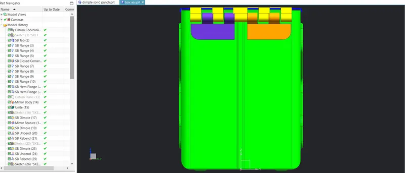
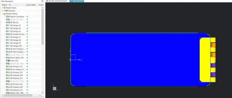
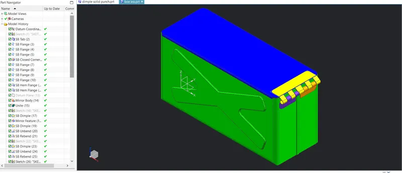
BOX ASSEMBLY IMAGES
FRONT VIEW
SIDE VIEW
TOP VIEW
ISOMETRIC VIEW
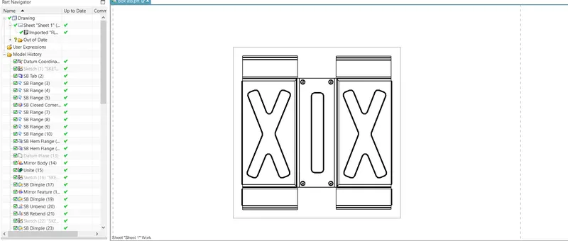
DRAFTING
Creating a new draft on A4 size sheet of flat pattern#1.
CONCLUSION
The box assembly sheet metal part is created using NX12 software.