Photo Realistic Rendering
MODELLING OF AMERICAN CHOPPER IN SOLIDWORKS
ABSTRACT
Modelling of American chopper in solidworks.
An elegant retro chopper is modeled using the solidworks software. A rough sketch is created in the ideation process. The chopper is created by modelling the individual solid parts, these solid parts are designed with perfectly predetermined sketch. After making the required solid parts, chopper is made by assembling these solid parts. During the assembly stage it is required to know way parts mate each other while in running condition. Decals, cameras, scenes and lights are added to the assembled chopper. To give a sturdy, glossy, speedy look or whatever the look interested in are made through the photoview360 and in the rendering stage. After rendering the chopper looks as much as realistic on road.
SOFTWARE USED
The parts are modelled in the solidworks and then it is rendered in photoview360 and solidworks visualize. Solidworks is a 3d modelling software and it also has add-ins like photview360 and solidworks visualize. The 3d parts are modeled form its 2d sketch.
OBJECTIVES
- To create the required individual parts for chopper
- To assemble all the individual parts
- To add decals , scenes, lights, cameras
- To render the chopper in photoview360 and in solidworks visualize
PROCESS FLOW
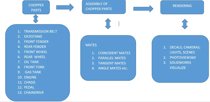
DEVELOPMENT OF INDIVIDUAL PARTS IN SOLIDWORKS
SKETCH ENTITIES AND TOOLS USED TO CREATE ALL THESE PARTS
- sketch
- offset
- extrude boss
- extrude cut
- fillet
- sketch fillet
- loft
- dome
- split
- trim
- revolve
- dynamic mirror
- blocks
- pattern
- combine
- shell
- chamfer
- revolve cut
- planes
- move/copy bodies
- projected curve
- sweep
- convert entities
- composite curve
- sweep surface
- loft surface
- fill surface
- surface trim
- surface knit
- sweep cut
BRIEF OF TOOLS
1. SKETCH
It is a 2d representation of a 3d part. It includes entities like line, rectangle, spline, circle, etc. It is a predetermined drawing with dimensions and relations.
- OFFSET
Offset uses selected edges, faces, splines, arcs at specified distance. It saves time by simply reproducing the sketch that we need.
- EXTRUDE BOSS
A selected closed sketch is extruded to the specified distance which in turn a solid is created.
- EXTRUDE CUT
A selected closed sketch on a 3d part is deleted or cut from the 3d part for a specified distance or upto next surface etc.
- FILLET
This is a type of surface continuities which is called G1 continuity. It is also called tangent continuity. It makes the selected faces or surfaces to be tangentially continuous.
- SKETCH FILLET
It is the fillet given in the 2d sketch itself and making the sketch continuous over the corners.
- LOFT
It generates surface by creating section profiles in different planes.
- DOME
Dome is a feature applied to any coplanar or non-coplanar faces which caps them with elliptical or circular profile.
- SPLIT
After projecting a sketch on a curved face or surface the split tool uses the sketch as trim tool and makes the part to be split. We can removed the selected parts.
- TRIM
The unwanted projections or sketch entities in 2d sketch are deleted by using this tool.
- REVOLVE boss/cut
A created sketch can be revolved around an axis to produce a 3d part. Mostly this is useful for producing symmetrical parts. It adds/removes the sketch.
- DYNAMIC MIRROR
It is used to mirror the sketch entities about the sketch previously created or about any axis.
- BLOCKS
We can create a 2d sketch and then make block for future use of that sketch in another sketch where it is related.
- PATTERN
There are linear pattern and circular pattern. It is used to increase the number of instances of the sketch/bodies that have created in a specified direction, Which makes the process much easier.
- COMBINE
This tool combines all the surfaces /bodies/faces into a one single body. All the bodies can be selected as a single body, useful while adding appearances/materials.
- SHELL
It is used when turning a solid body into a shell body with the specified shell thickness. It is for creating parts like thin cylinders.
- CHAMFER
It converts the squared edges into a sloped edges.
- PLANES
This is a very useful tool to add a new plane in a specified direction which is handful for creating sketches in complex faces.
- MOVE/COPY BODIES
This is used to distance the selected bodies or to copy them.
- PROJECTED CURVE
This is a curve suspended in 3d world and it is created using 2d sketches from different combination of views like front and top view, top and side view, etc.
- SWEEP
The 2d sketch it swept along the curve and makes it a 3d part for example lie piping, tubing etc.
- CONVERT ENTITIES
It is used when we need a direct sketch from a previous one or its projection on the current plane of sketch.
- COMPOSITE CURVE
This tool combines two or more curves which is obtained from a projected curve.
- SWEEP SURFACE
A surface is created along desired direction from as section curve.
- LOFT SURFACE
A surface created by multiple selected edges with tangency.
- FILLS URFACE
A surface created by selecting the edges which are closed and the curvature has to be adjusted to have a smooth finish.
- SURFACE TRIM
It is to cut away the materials from the surfaces.
- KNIT SURFACE
It is more like stitching the clothes. The surfaces are stitched together by adjusting the gaps between them. They can be selected all as a one surface.
- SWEEP CUT
It removes the material from the 3d part in the direction of the specified curve.
- TRANSMISSION BELT
Functions as power transmission.
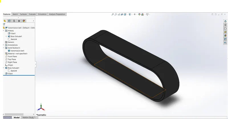
Features used
- sketch
- offset
- fillet
- extrude
- appearances
2. KICK STAND
The chopper in leaning on the kickstand on road.
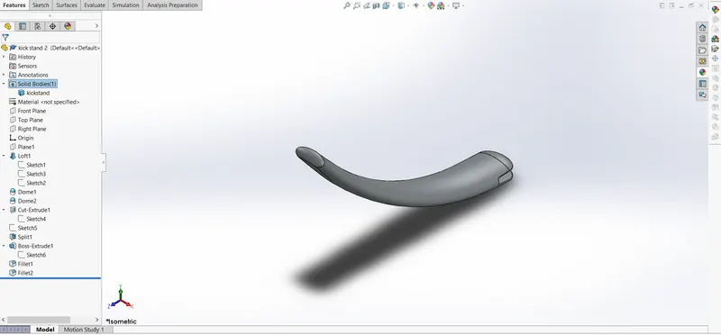
Features used
- sketch
- loft
- dome
- extrude boss&cut
- fillet
- split
3. FRONT FENDER
They reduce the grime sprayed on the chopper and grit dirts. This element is static it doesn’t make any relative motion between them.

Features used
- sketch
- offset
- trim
- revolve
- mirror
- split
- appearances
- REAR FENDER
This is as same as the front fender.
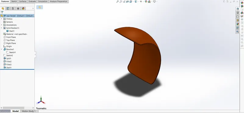
Features used
- sketch
- offset
- trim
- revolve
- mirror
- appearances
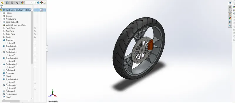
5. FRONT WHEEL
This is an alloy wheel mounted with caliper and the brake disc.
Features used
- sketch
- revolve
- trim
- sketch fillet
- boss extrude
- revolve cut
- linear pattern
- chamfer
- extrude cut
- circular pattern
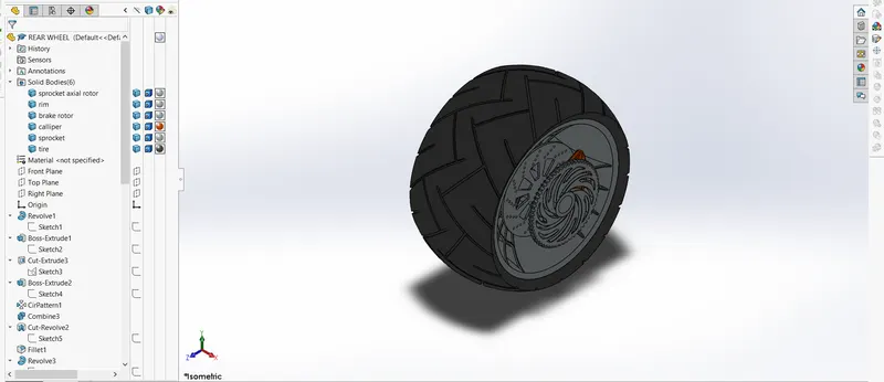
6. REAR WHEEL
Rear wheel is slightly wider than front wheel it also attached with chain sprocket.
Features used
- sketch
- revolve
- trim
- sketch fillet
- boss extrude
- revolve cut
- linear pattern
- chamfer
- extrude cut
- circular pattern
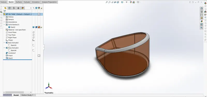
7. OIL TANK
The required fluids for the chopper is placed in oil tank, it is given a transparent look for its shell type nature.
Features used
- sketch
- extrude boss
- fillet
- shell
- combine
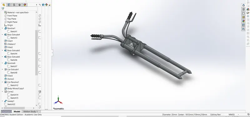
8.FRONT FORK
The main steering handle bar with 70 degree constraint is created.
Features used
- sketch
- extrude
- trim
- revolve
- split
- move/copy bodies
- dome
- mirror
- combine
- projected curve
- sweep
9. GAS TANK
This serves as a fuel tank and also a seat for the rider.
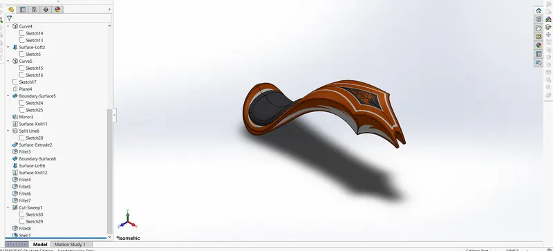
Features used
- trim
- projected curve
- sweep curve
- loft surface
- fills surface
- surface trim
- surface knit
- Sweep cut
- Fillet
10.ENGINE
The power house of the chopper is built with exhaust manifolds.
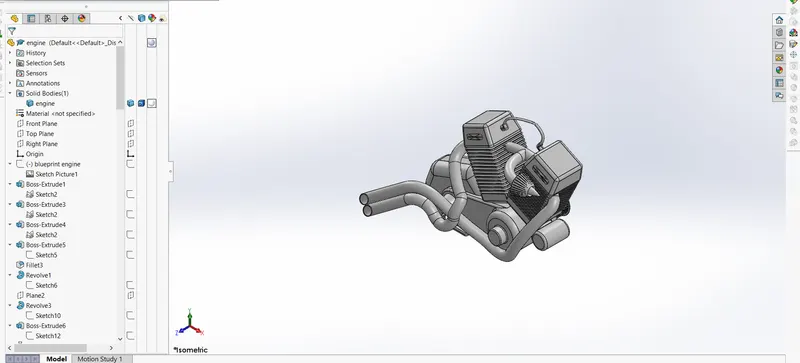
Features used
- Sketch
- Trim
- Revolve
- Extrude boss
- Extrude cut
- Offset
- Dome
- Fillet
- Projected curve
- Composite curve
- Sweep
- Mirror
- Circular pattern
- Split
11. PEDAL
It is positioned on the chasis.
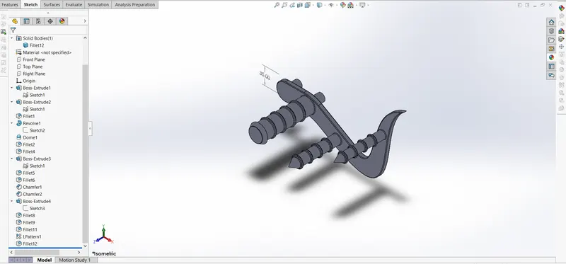
Features used
- Sketch
- Extrude
- Fillet
- Linear pattern
- Dome
- Chamfer
12.CHASIS
This is the main skeleton of the chopper where all the parts have been positioned and constrained.
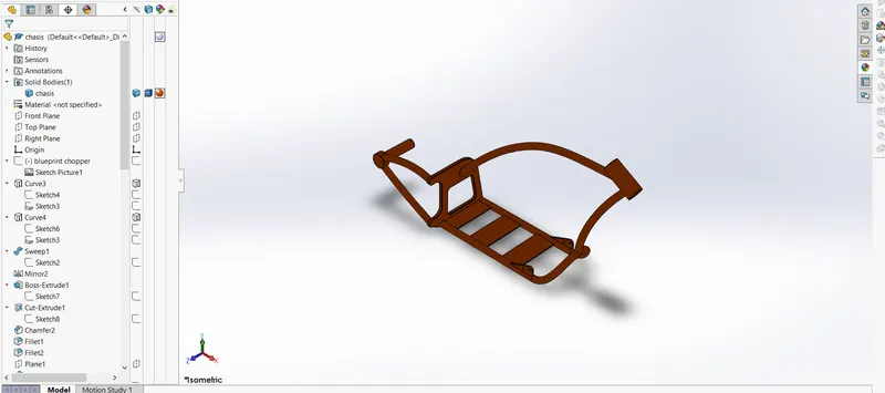
Features used
- Sketch
- Offset
- Convert entities
- Projected curve
- Trim
- Sweep
- Split
- Revolve
- Extrude cut
- Fillet
- Combine
13. CHAINDRIVE
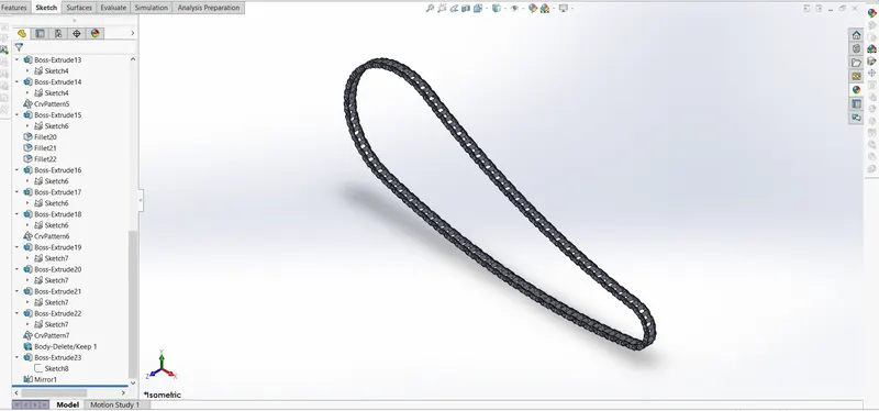
Features used
- sketch
- fillet
- trim
- blocks
- extrude
- pattern
- appearances
ASSEMBLY OF CHOPPER PARTS
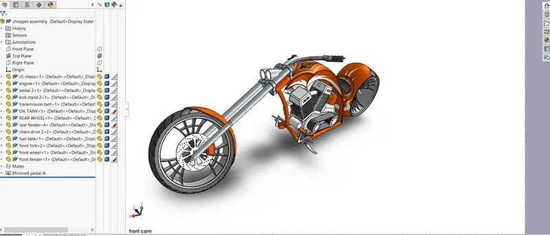
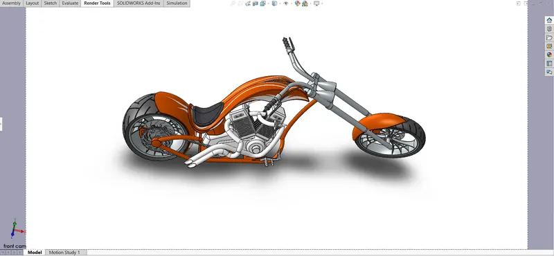
In which the assembly is completed by inserting all the individual parts one after another and also constraining them is required. The parts are mated with one another by executing a relation in between them. All required relations are performed to make the assembly fixed.
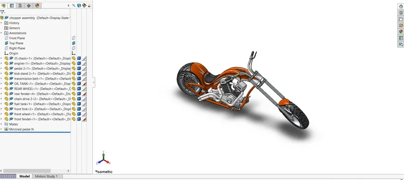
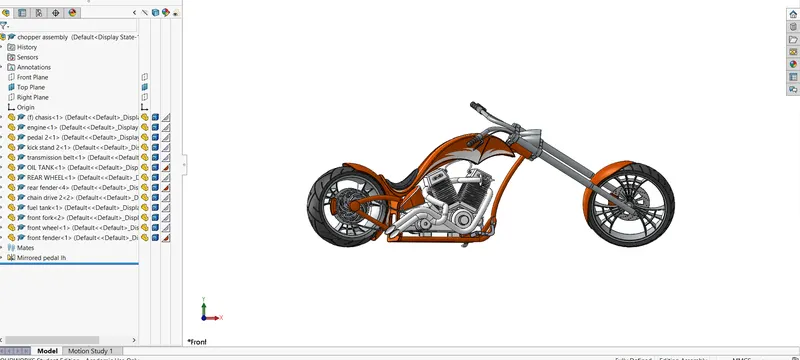
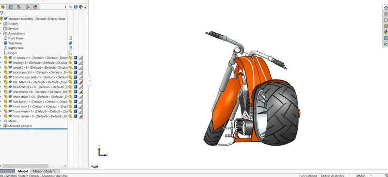
Features used
- Inserting components
- Mates
Mates
Mates are so important while assembly, it decides the relative position of the interlinked parts with one another. There are several mates like parallel, coincident, tangent etc. These mates makes the assembly constraint.
RENDERING
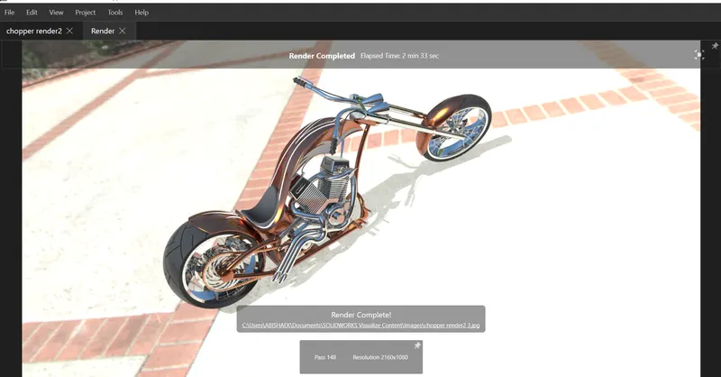
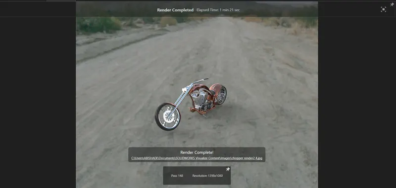
Rendering is mainly done to have realistic perspective of the developed product, which makes the customer much easier to grasp the intent of the design without knowing its technical detailing, it also makes the product so pleasant with its high in-depth quality of imaging.
This can be done by the following ways
- Photoview360
- Solidworks visualize
- PHOTOVIEW360
It is an add-inn in soliworks software which is helpful in rendering the chopper in solidworks itself. There is preview and final renders available
- SOLIDWORKS VISUALIZE
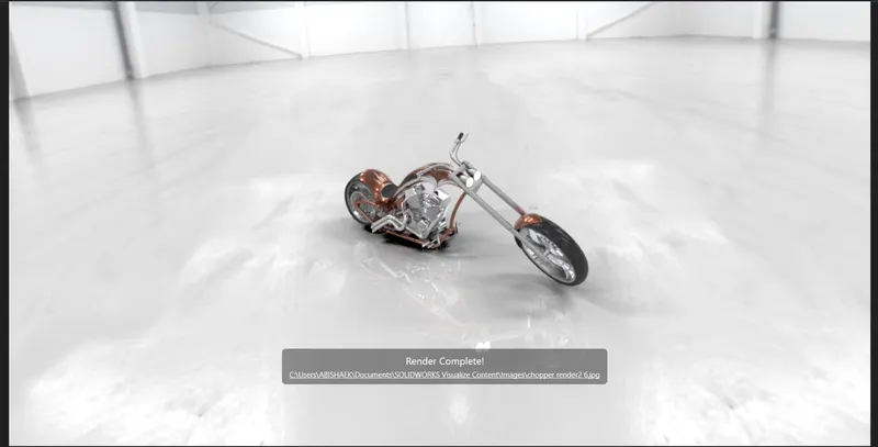
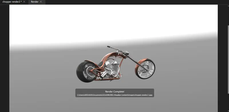
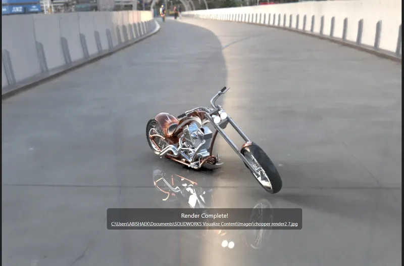
This results in high quality imaging, background can be changed according to the mood board. This gives a highly realistic render results with the apt background scenes and lightings.
CONCLUSION
Therefore the chopper in assembled from its individual parts and it is rendered to have those desired mood board looks.