Advanced Sheet Metal Design Using NX Cad Challenge_5_Odd Shaped Enclosure
DESIGNING ODD SHAPED ENCLOSURE
OBJECTIVE
- To create a solid body
- To convert sheet metal from solid
INTRODUCTION
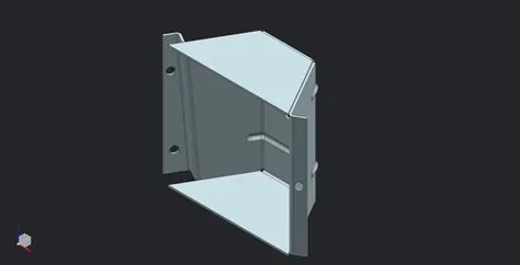
A very complex shapes or weird shapes cannot b sheet metaled directly. It can be done by modeling a solid body and then performing the sheet metal from solid command to convert the solid body into a sheet metal. Aftermath of converting into sheet metal the necessary feature operations can be done.
DESIGN METHODOLOGY
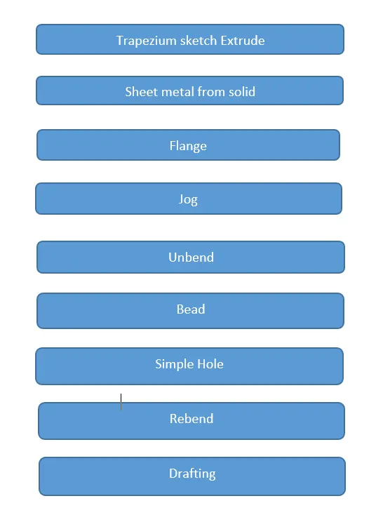
TOOLS AND FEATURES USED ON SHEETMETAL TO DESIGN ODD ENCLOSURE
- Sketch
- Extrude
- Flange
- Unbend
- Hole
- Bead
- Re bend
- Drafting
- Base view
TOOL AND FEATURE DESCRIPTION
- SKETCH
It is a 2d representation of a 3d part. It includes entities like line, rectangle, spline, circle, etc. It is a predetermined drawing with dimensions and relations.
- EXTRUDE
The sketch is extruded to some distance and results into a solid body.
- FLANGE
It is created with one or more edges at specified location. The minimum flange length must be at least four times the thickness of the sheet metal. Bend radius is equal to the sheet metal thickness.
- UNBEND
It makes the part unbend, that is all the features done are made flat. This is useful while sketching on the corners and bend areas.
- BEAD
It lifts material along the sketch. it strenghthen the product also increases the flex.
- REBEND
This command puts back all the bends already created also along with new features included while in unbent state.
- DRAFTING
This command is to have 2D drawing of the sheet metal part created.
- BASE VIEW
It specifies the location, orientation, view and scale of the part for drafting.
STANDARD VIEWS
FRONT VIEW
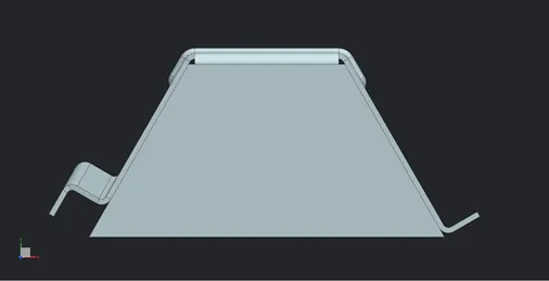
TOP VIEW
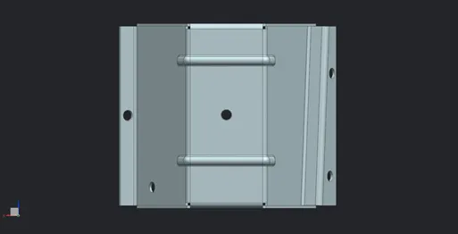
SIDE VIEW
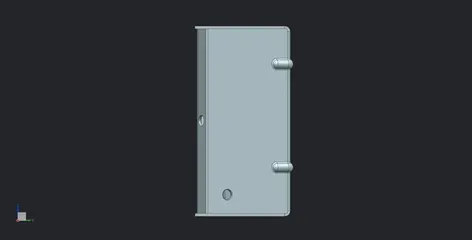
ISOMETRIC VIEW
DRAFTING
- Sheet – A3
Scale – 1:2
Flat pattern#1
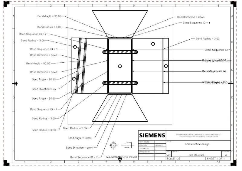
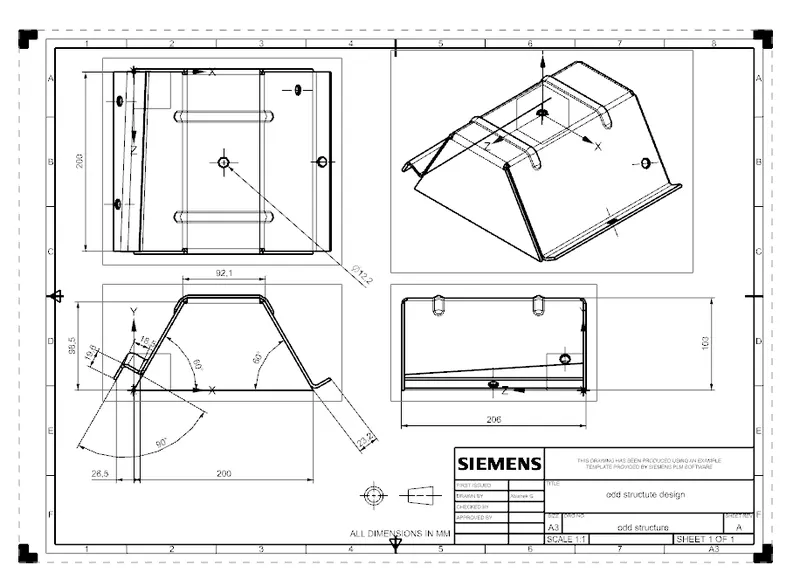
2. Sheet – A3
Scale - 1:2
Standard views with template
Conclusion
Hence the enclosure design is successfully created.