Week 9 - Project - Master Section Development
PART I: Creating tooling axis
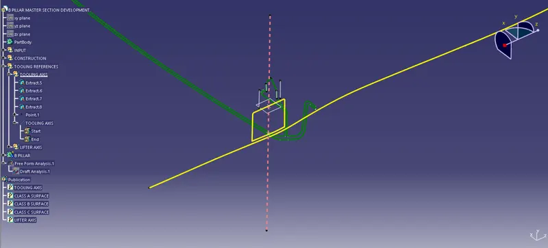
PART II: Construction
1) Class A surface with flange
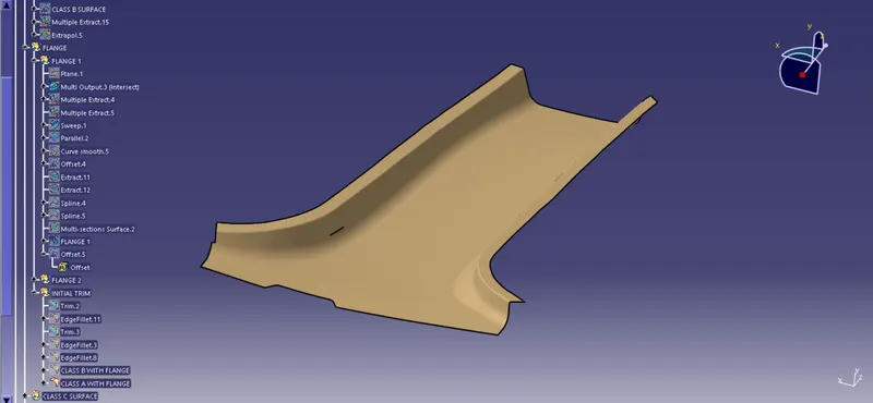
2) B Surface
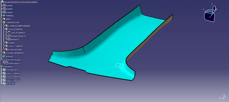
B surface with flange
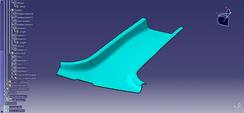
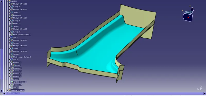
3) C Surface
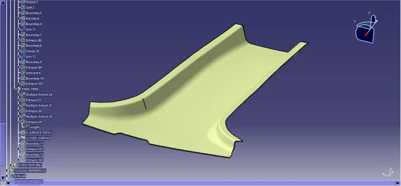
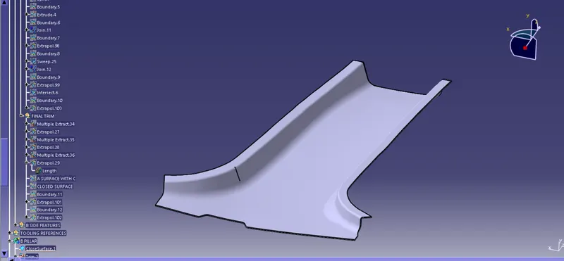
4) Closed surface
5) Doghouse and four way locator
Sketches
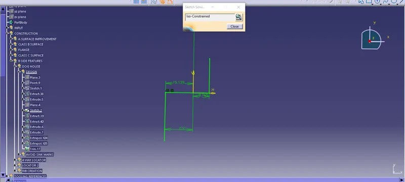
Doghouse
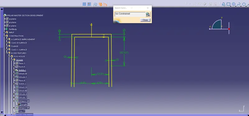
Extracting surfaces
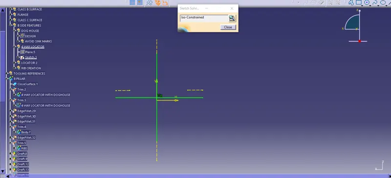
Four way locator
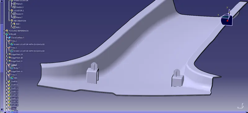
Doghouse and four way locator
6) Creating lifter axis
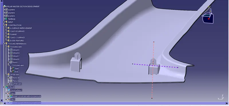
7) Ribs
Sketches
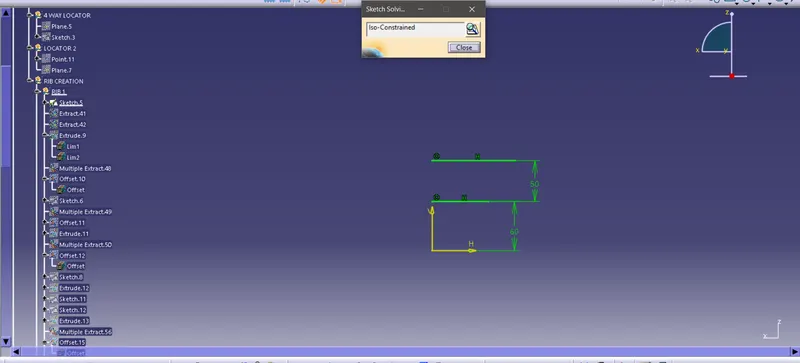
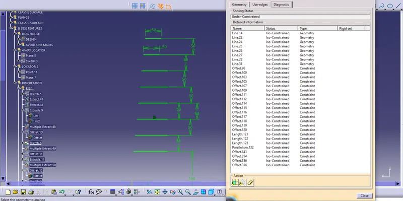
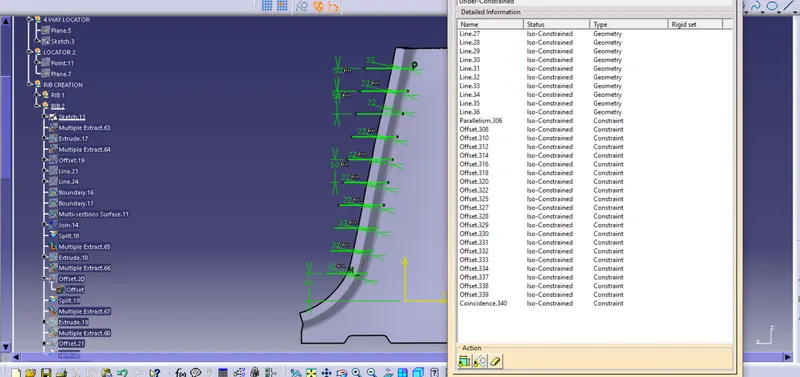
Ribs on B Pillar
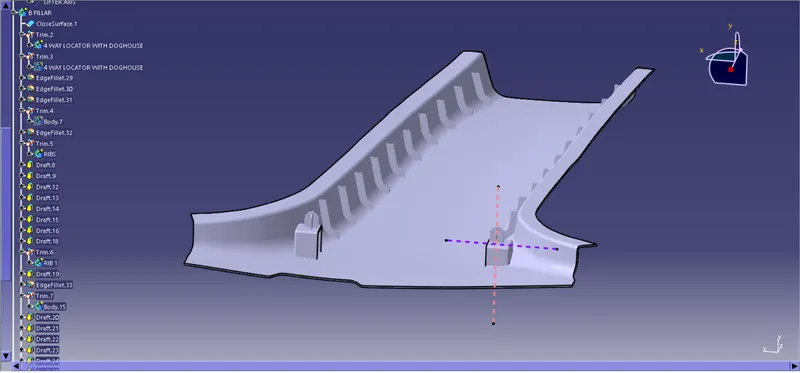
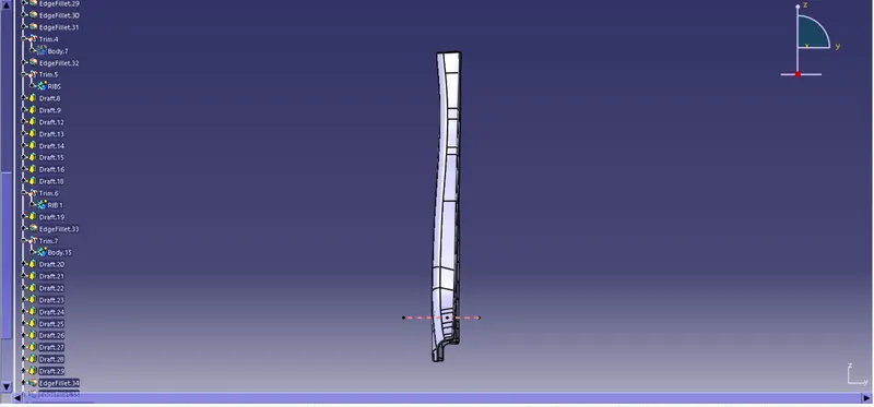
B Pillar Views
1. Isometric View
2. Front View
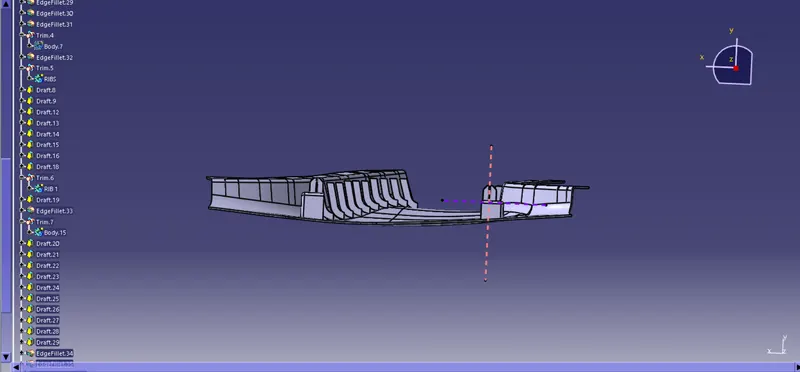
3. Top View
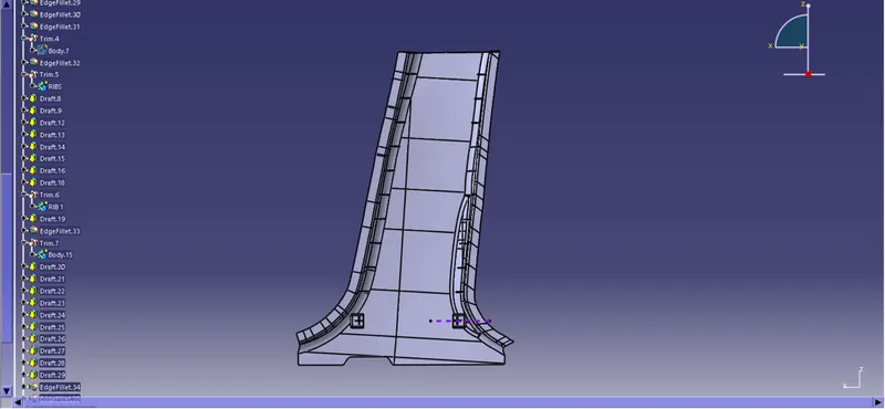
4. Side View
PART III: Draft Analysis
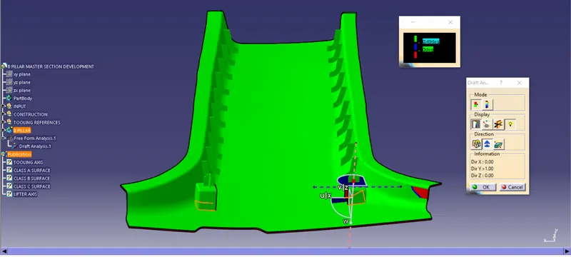
1) A Surface draft analysis
1. Isometric View
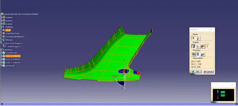
2. Front View
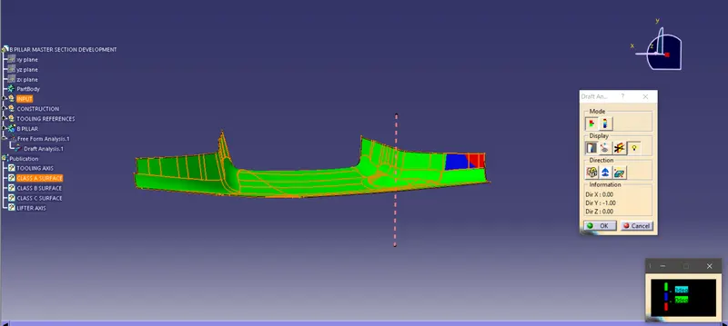
3. Top View
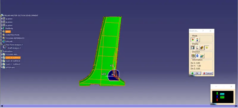
4. Side View
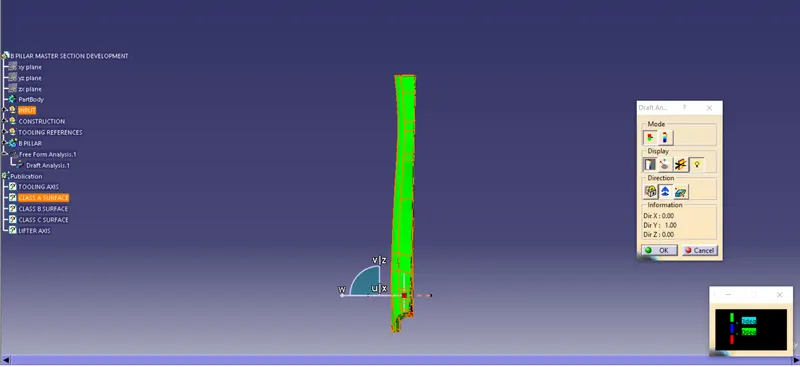
Surfaces that has got errors
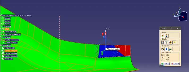
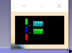
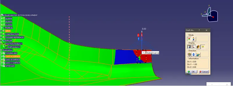
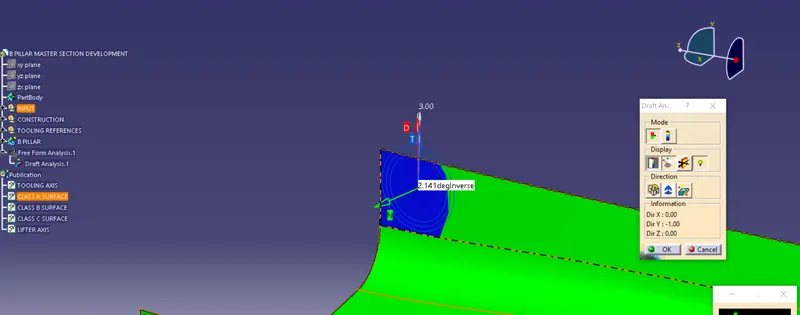
- The green color represents angle of surface with respect to tooling axis being greater than 3 degrees.
- The blue color represents angle between 0 and 2 degrees.
- The red color represnts angle lesser than 0 degrees. It represnets errorneous draft angle that needs to be corrected.
2) B Pillar solid body
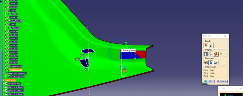
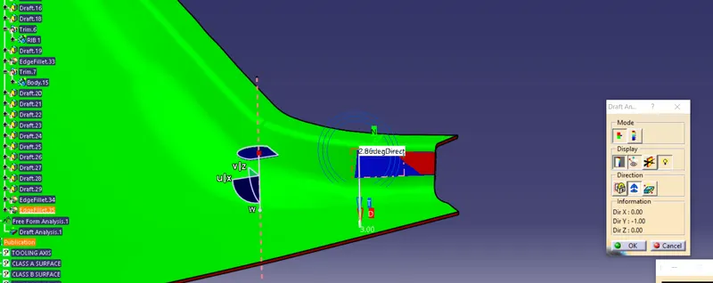
The maximum draft angle is 2.8 degree and minimus is -1.48
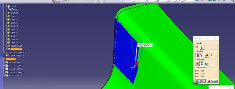
The maximum draft angle is 2.8 degree
The draft anlysis of class C surfaces is as follow:

It follows 3 degree draft on all the surfaces as shown above
3) Doghouse and four way locator
Draft analysis of Screw Boss 1
- With respect to main tooling axis
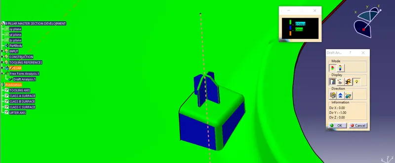
The minimum angle is 0.5 degree over blue faces and 3 degrees on the other faces.
- With respect to lifter axis
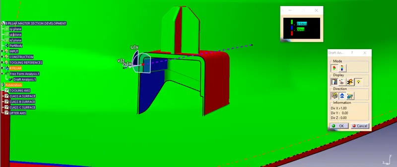
The minimum angle is 0.5 degree over blue faces and 3 degrees on the other faces.
Draft analysis of Screw Boss 2
- With respect to main tooling axis
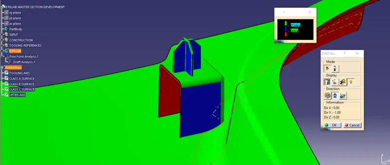
The minimum angle is 0.5 degree over blue faces and 3 degrees on the other faces.
- With respect to lifter axis
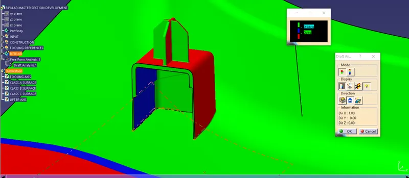
The minimum angle is 0.5 degree over blue faces and 3 degrees on the other faces.
Draft analysis of Ribs