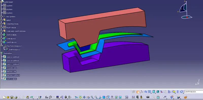
Week 8 - Challenge 5 - Core & Cavity Design
PART I: Performing draft analysis on Switch Bezel component
1. Isometric View
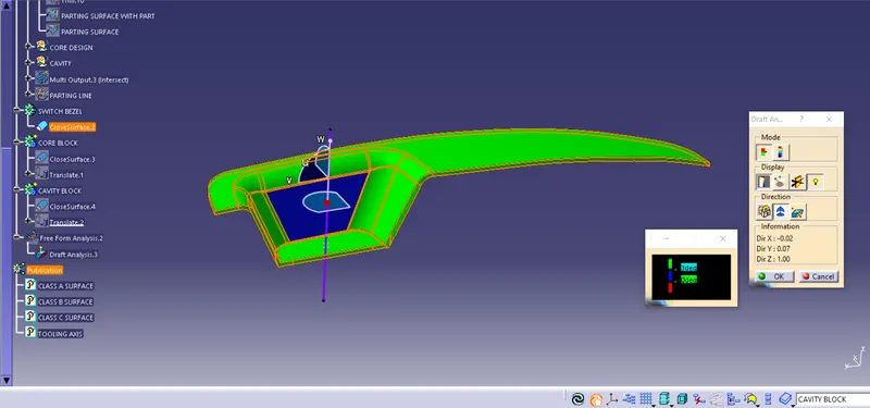
2. Front View
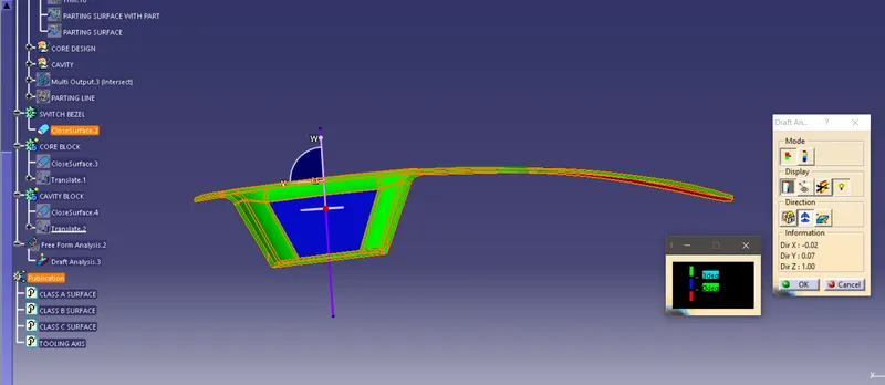
3. Top View
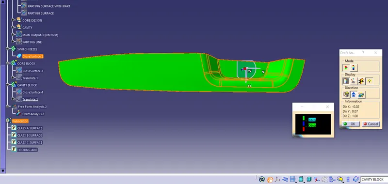
4. Side View
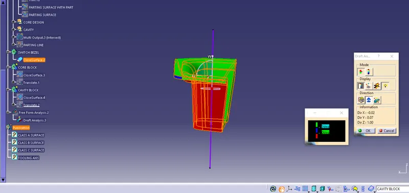
Draft Analysis Report:
Report:
- The green color represents angle of surface with respect to tooling axis being greater than 3 degrees.
- The blue color represents angle between 0 and 3 degrees.
- The red color represnts angle lesser than 0 degrees. It represnets errorneous draft angle that needs to be corrected.
PART II: Creation of Core and Cavity Blocks
Creation of Core Block:
1. A Parting surface with a component in it was created.
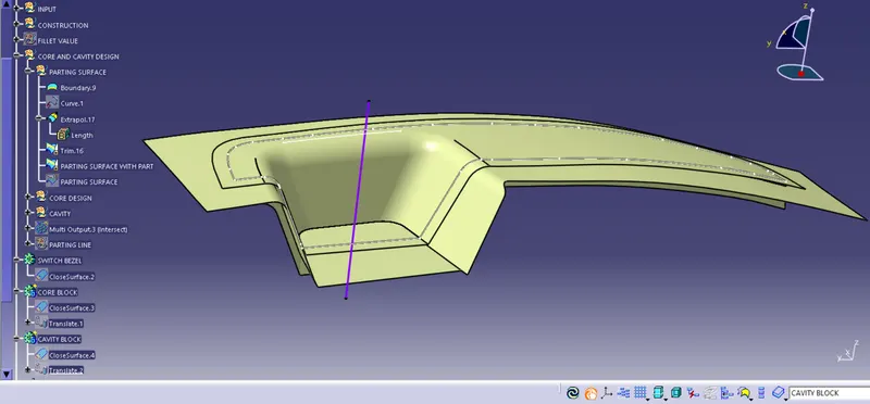
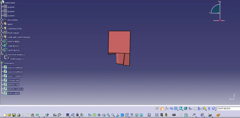
2. The parting surface was trimmed with an extrude (with reference anlge of tooling axis) of a rectangle that enclosed the component design that resulted in creation of core block
1. Isometric View
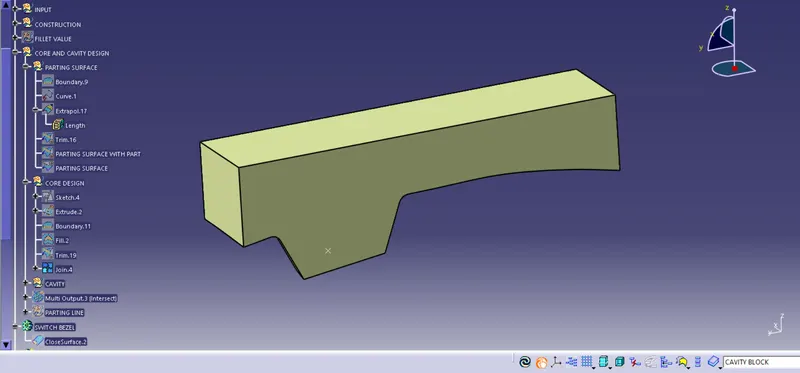
2. Front View
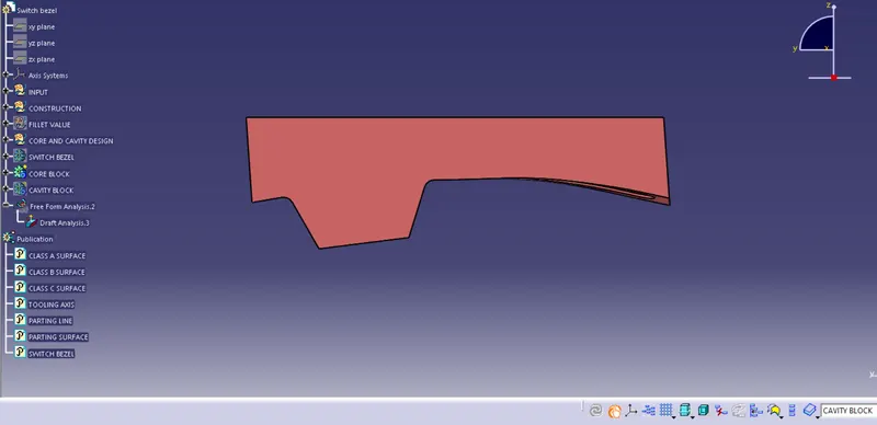
3. Top View
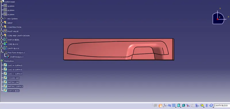
4. Side View
Creation of cavity block
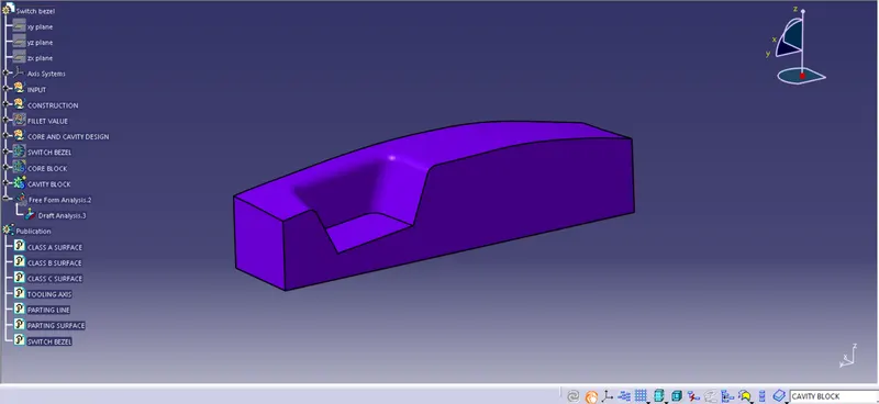
The CLASS B surface was trimmed with an extrude of rectangle along the tooling axis.
1. Isometric View
2. Front View
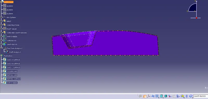
3. Top View
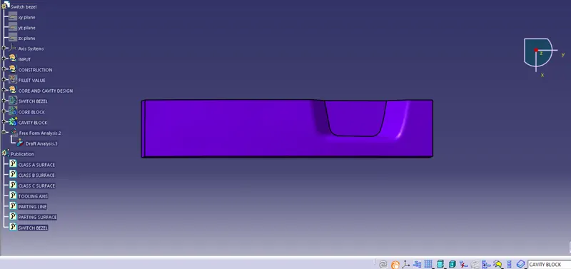
4. Side View
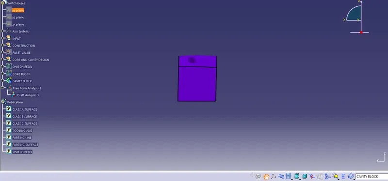
Core and cavity design with componenet and parting surface: