Week 8 - Challenge 3 - Switch Bezel Design
PART I: Creation of tooling axis
Tooling axis is created to determine the direction of mold opening and closing. Draft around the different faces is provided along tooling axis.
1. Creating tooling lines along Y direction
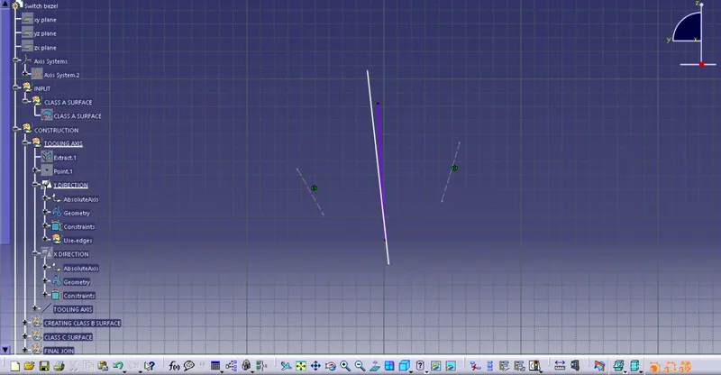
2. Creating tooling line along X direction.
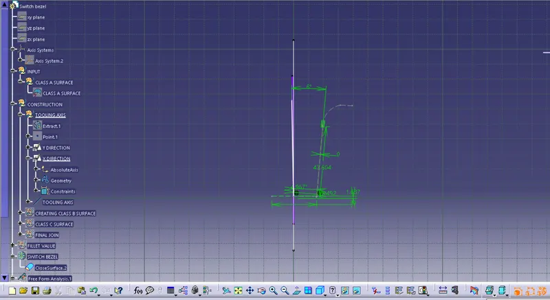
3. Creating tooling axis with respect to tooling lines along X and Y direction by using 'bisecting' option from 'line' toolbar.
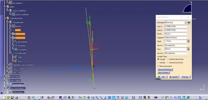
PART II: PERFROMING DRAFT ANALYSIS
Draft analysis: Draft is an angle provided on the faces of a component with respect to the tooling axis. Providing draft ensures easy removal of component from the mold cavity. Draft analysis help us determine draft of every faces/surface of a component with respect to the tooling axis.
Draft analysis is as follow:
1. We have to check continuity of the surface.
2. We find tooling direction with the help of tooling axis.
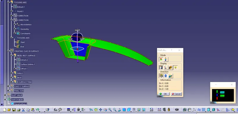
3. By using 'draft analysis' tool we put compass on the tooling axis, and get the results of draft analysis.
Draft analysis on CLASS A SURFACE:
1) Isometric View
2. Front View:
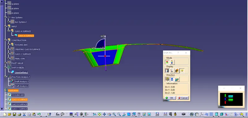
3. Top View
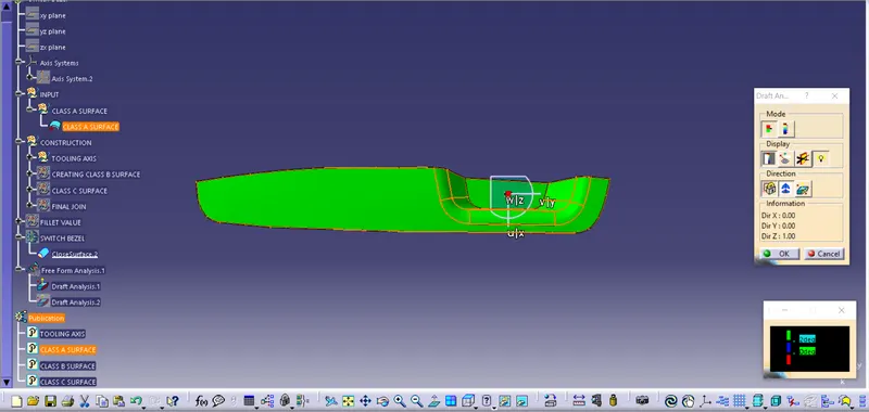
3. Side View
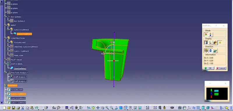
Report:
- The green color represents angle of surface with respect to tooling axis being greater than 2 degrees.
- The blue color represents angle between 0 and 2 degrees.
- The red color represnts angle lesser than 0 degrees. It represnets errorneous draft angle that needs to be corrected.
PART III: CREATING CLASS B AND C SURFACE:
1. Creating CLASS B SURFACE:
- It is created from CLASS A SURFACE.
- Surfaces from CLASS A are extracted.
- The same surfaces are untrimmed.
- These surfaces are extrpolated
- The extrapoated surface is offset by the given values.
1) Creating BEZEL REST surface from class A Surface:
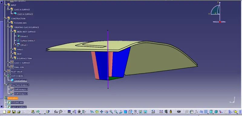
2) Creating WALLS from CLASS A
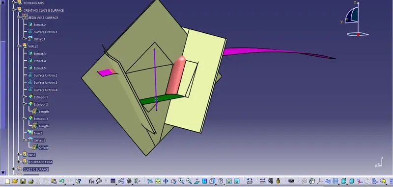
3. Creating BASE offeset from CLASS A
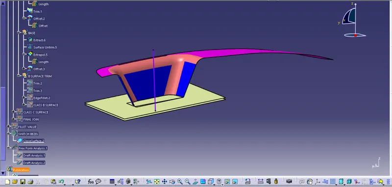
4. Creating a final trimmed part that is CLASS B SURFACE with the help of offeseted surfaces.
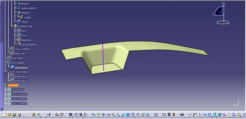
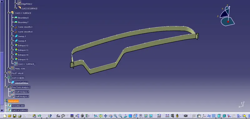
2. Creating CLASS C SURFACE:
- Creating boundaries from CLASS A surface.
- Performing sweep operations at 3 degrees along the tooling axis from those boundaries.
- Connecting the swept part with the help of trim. The final trim is CLASS C SURFACE
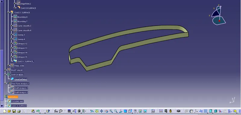
3. Creating a final surface:
By joining CLASS A, B, and C SURFACES, a final surface is created with the help of 'join' tool.
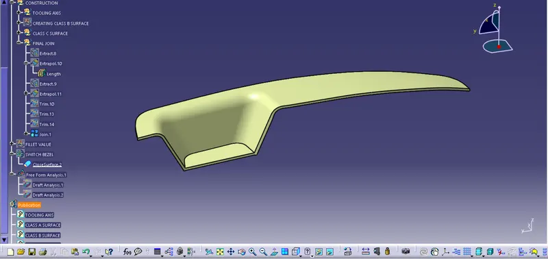
4. Creating a closed surface of the plastic component.
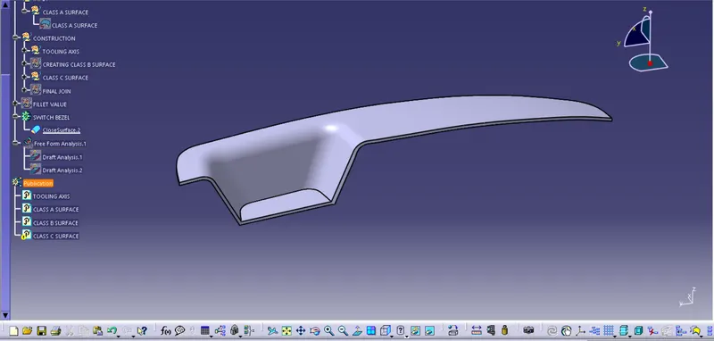
PERFORMING DRAFT ANALYSIS ON CLOSED SURFACE:
1. Isomtric View
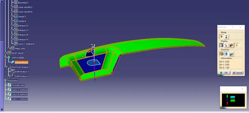
2. Front View
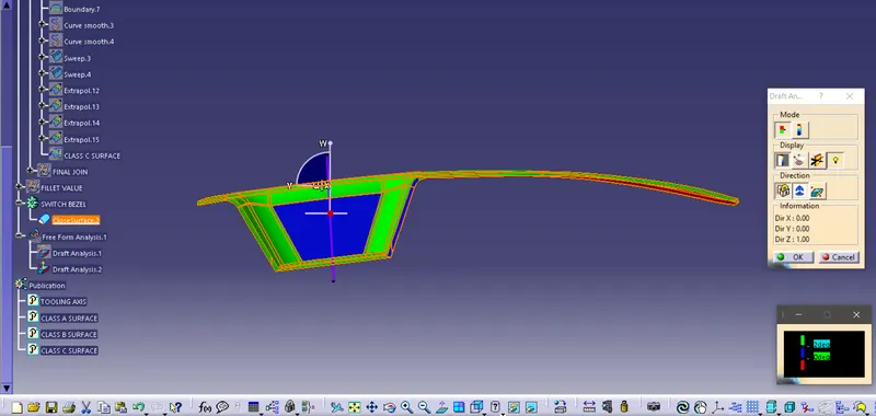
3. Top View
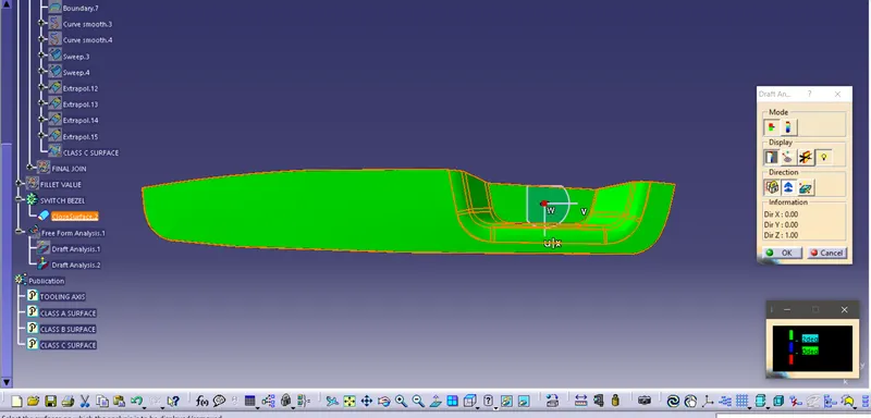
4. Side View
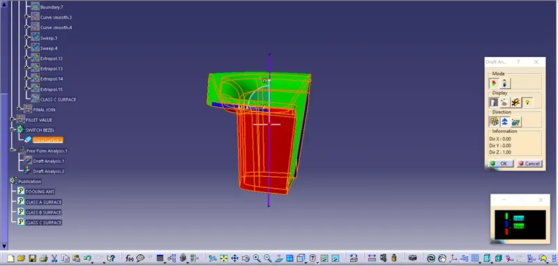
Report:
- The green color represents angle of surface with respect to tooling axis being greater than 2 degrees.
- The blue color represents angle between 0 and 2 degrees.
- The red color represnts angle lesser than 0 degrees. It represnets errorneous draft angle that needs to be corrected.