Design of B-Pillar Trim Panel
Problem Statement: Create a closed body of B Trim following the given master section along with engineering features using surface commands.
Introduction:
B Pillar
B Pillar is the most complex component or structure of the vehicle body. This is because the front door attaches to the B pillar and the rear door hinges to the B pillar. The B Pillar is welded to the top panel of the car and to the floor panel of the car. Hence B-Pillar provides structural support to the roof.
A surface:
A surface is the styling surface that is visible to the consumer and gives an aesthetic look for the model designed. Surfaces which is having curvature continuity is also called Class A Surface. Engineering features are not added to this surface.
B Surface:
Class B Surface is the invisible surface that includes all the engineering features such as dog house, locators, ribs, flanges, etc. This surface is the direct offset of the Class A surface which gives thickness to the component.
C Surface:
This surface is the combination of the Class A and Class B surfaces.
Tooling Axis:
It is the direction in which the component is removed from the mold cavity.
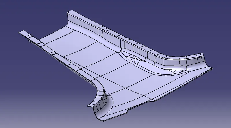
Given Class A surface:
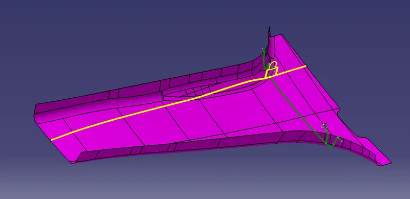
The given class A surface is checked for discontinuity and corrected.
Improved Class A surface
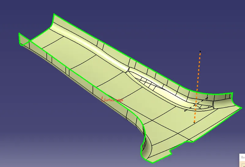
A Surface with flange following the given master section:
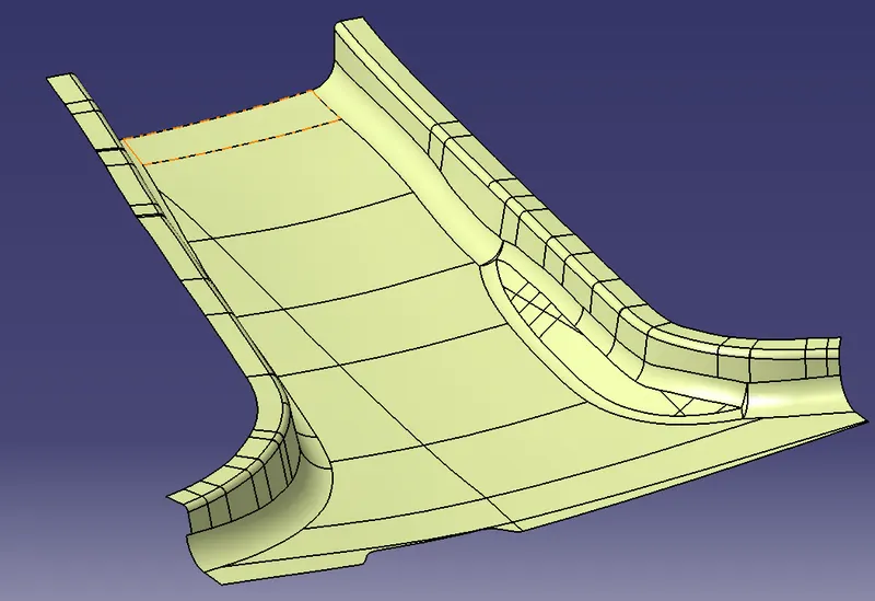
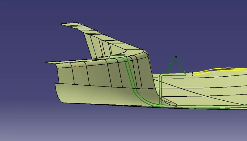
Class B Surface creation:
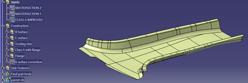
Class B surface is offset for 2mm which is obtained from the design master section.
Class C surface creation:
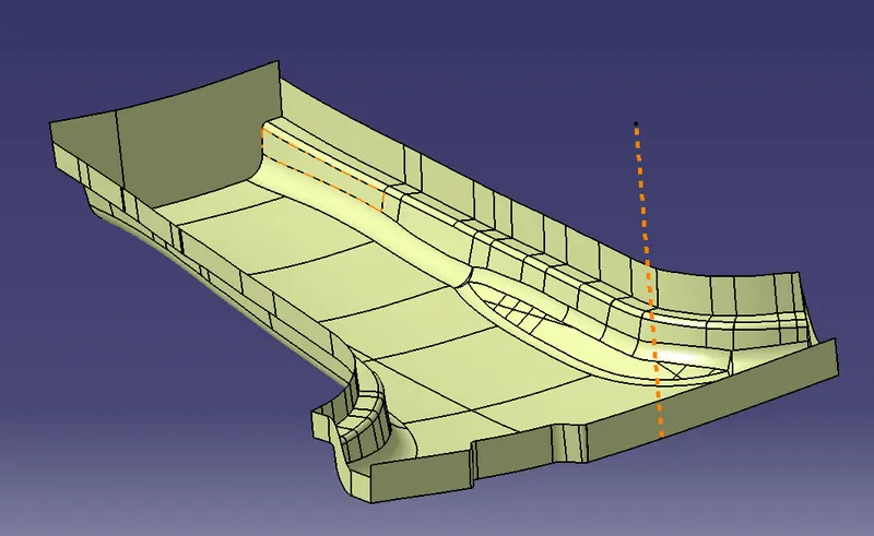
Class C surface is created with a nominal draft direction of 3 degrees with the tooling direction.
Closed Surface:
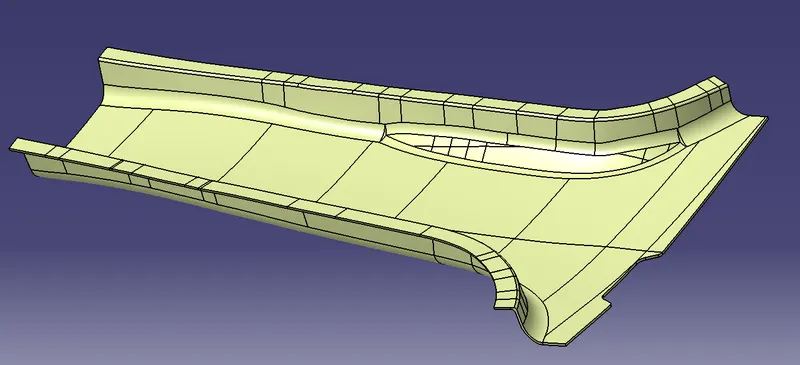
Check to ensure that there is no opening in the closed surface using boundary command
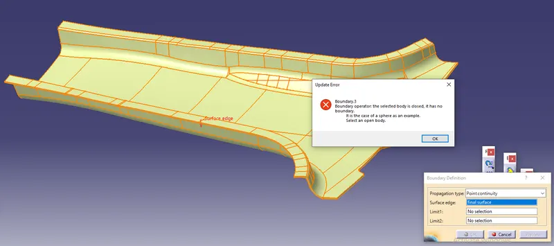
As it displays an error saying this command is applicable for open boundaries, it can be confirmed that the created model using the surface workbench is closed.
The closed body is created using the command closed body in the part workbench
Engineering Features
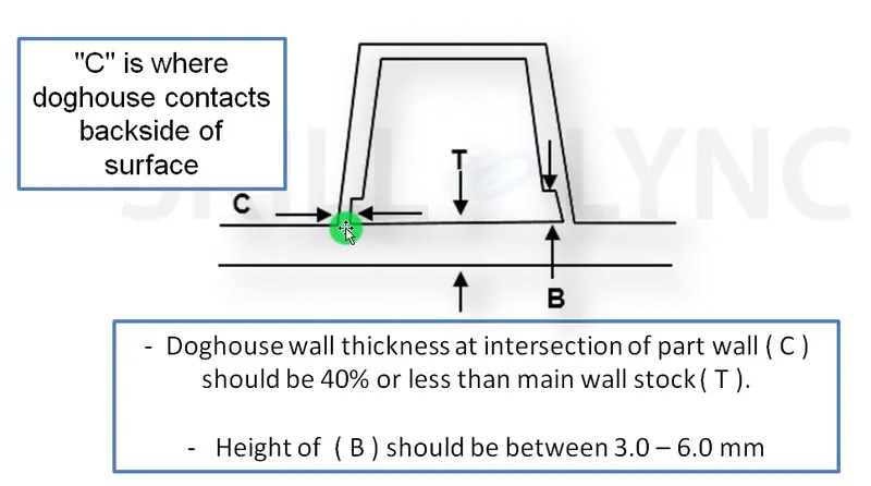
Dog House design rules
1. A minimum draft angle of 0.5 degrees should be given to the faces of the dog houses.
2. Dog house wall thickness at the intersection of the part wall should be 40% or less than the main wall thickness.
3. Side core axis should be created in order to clear the draft direction of the internal faces of the dog house.
Ribs Design Rules:
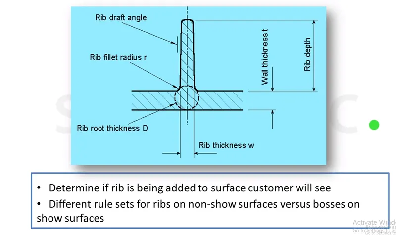
Rib draft angle: 0.5 degree
Rib fillet radius : 0.5 mm
Length of the rib tip: 0.75mm
4 Way locators
1. 4-way locators are designed with a thickness of 0.4 times the part thickness.
2. Fillet radius of 0.5 mm is given to avoid sharp edges.
Sketches for the Dog House
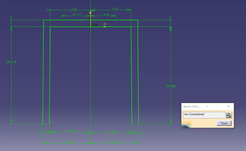
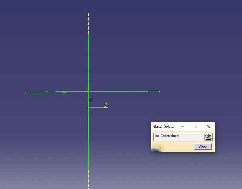
It can be seen the form sketch solving status that the created sketch is fully constrained. This sketch is created using the master section given.
Sketches for the 4-way locator:
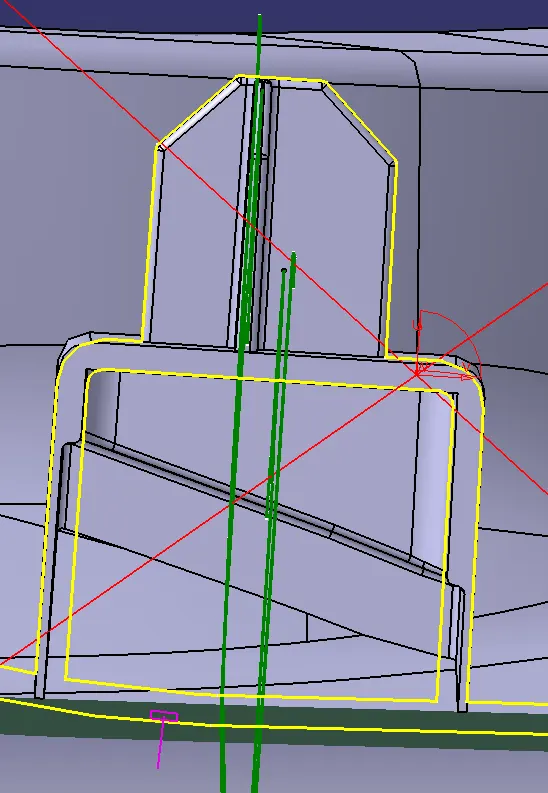
Dog House with 4 way locator:
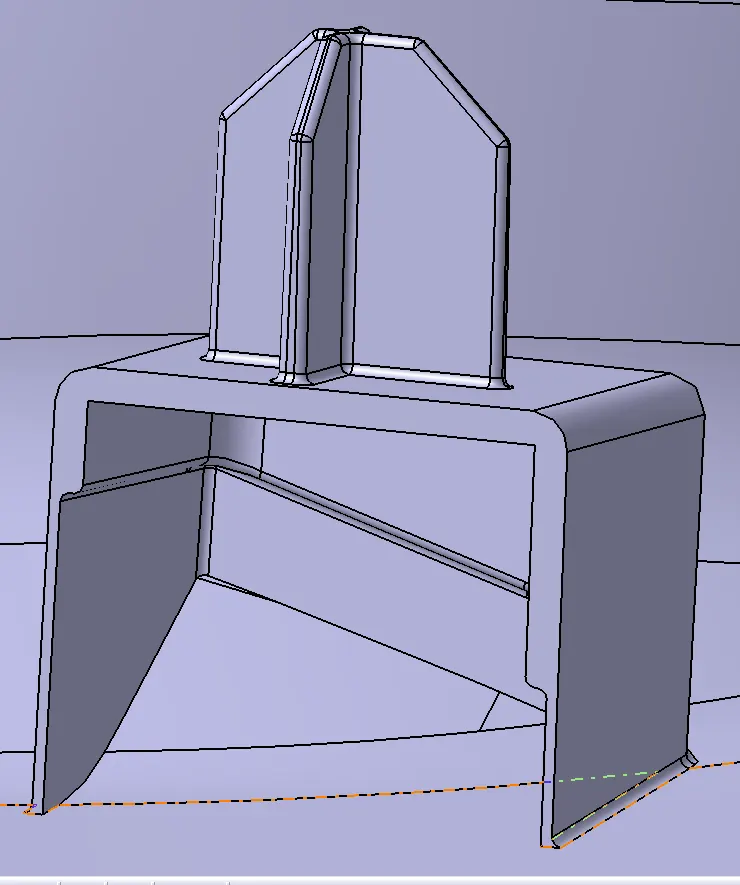
Dog House following Master Section:
Draft Analysis:
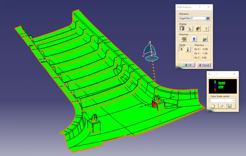
Draft Analysis is performed to check the drafted component is easily removed after the manufacturing process. It is performed based on the color ranges on identifying elements based on the deviation of the draft face with respect to the tooling axis.
Draft Analysis for A surface with nominal 3-degree draft angle:
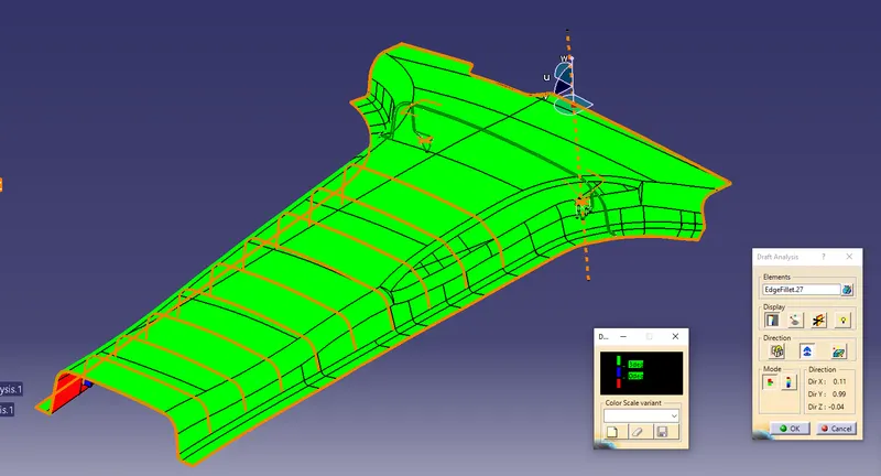
Draft Analysis for B surface with a nominal draft of 3 degrees.
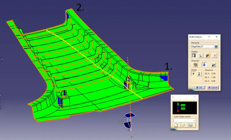
Problem Area 1: Problem Area 2:
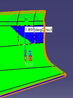
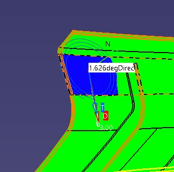
Dog House draft analysis along Main tooling Axis with 0.5 degrees draft angle
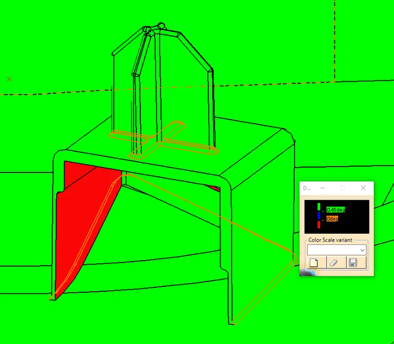
Dog House draft analysis with Side Core Axis with 0.5 degrees draft angle
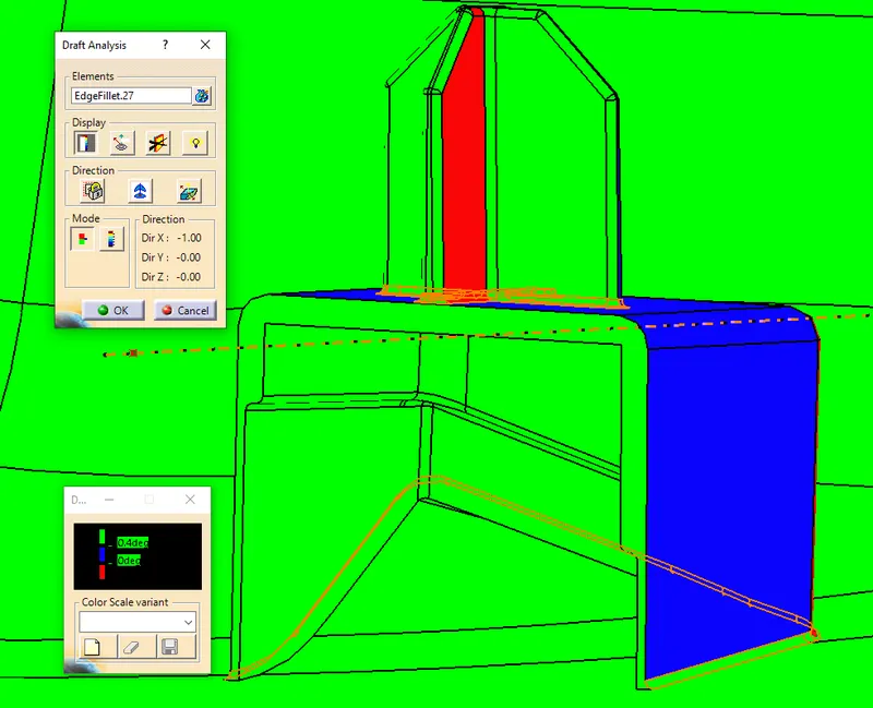
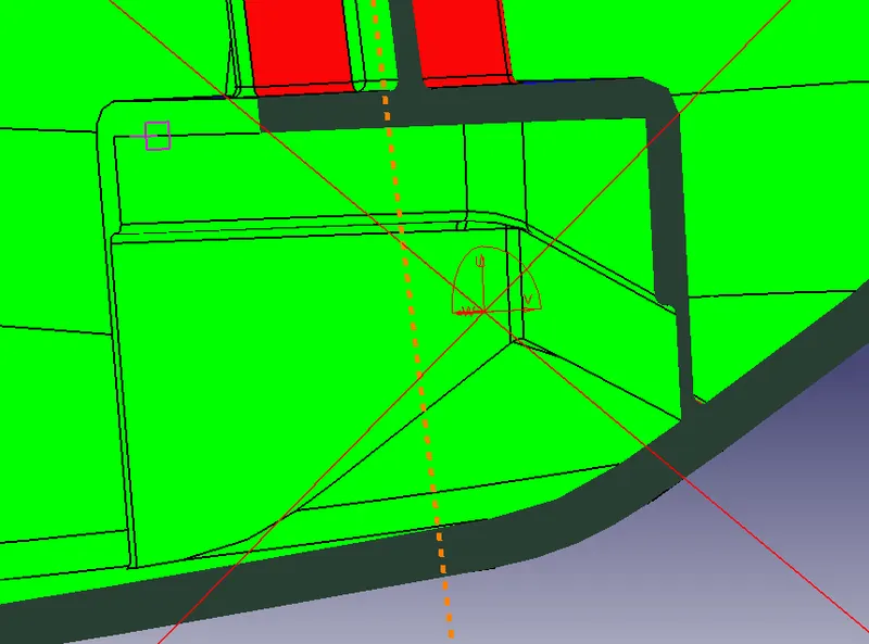
Dynamic Section View of the dog house
Draft analysis for the ribs with 0.5 degrees draft angle:
Final Component with attachment features:
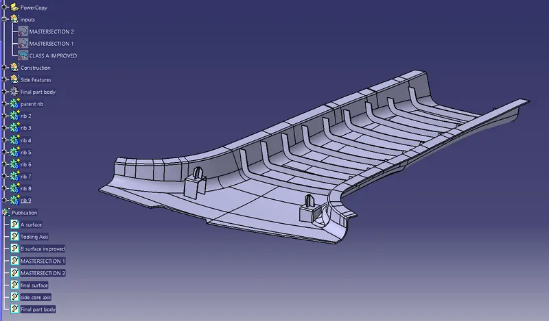
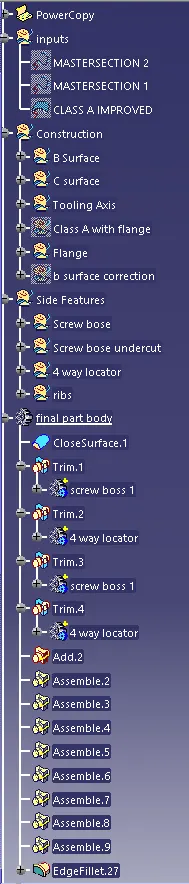
Tree Structure:
Conclusion:
1. The B Pillar trim is created using a generative shape design workbench.
2. The model is designed with the nominal draft angle of 3 degrees for the component and 0.5 degrees for the engineering features.
3. The Closed body of the model is created using close body command in part design workbench.
4. The engineering features in the model are designed following the design rules.