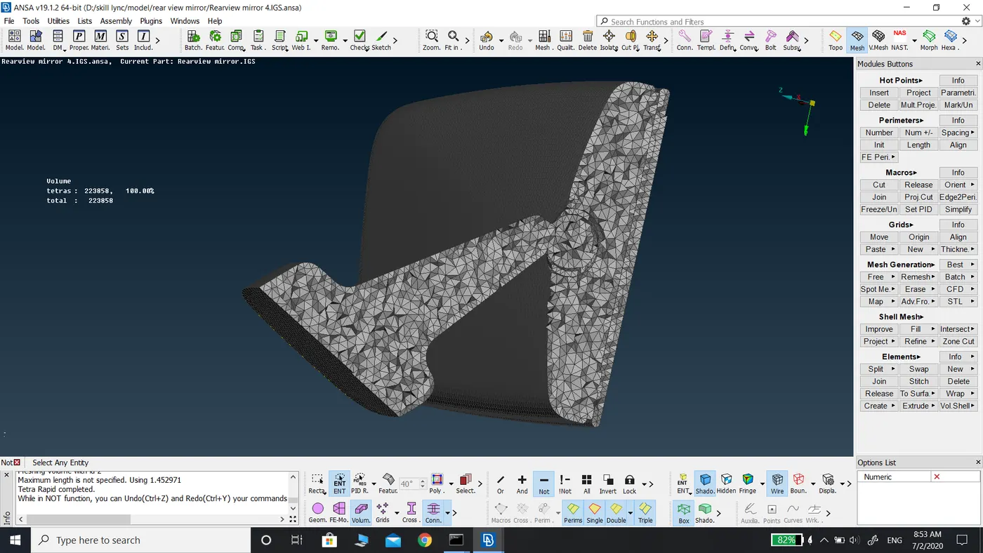
Volumetric meshing for Rear View Mirror
Report on Meshing of Rear View Mirror using Volumetric mesh
Aim: To check for the geometrical errors and mesh with the given element quality criteria. Use Tetra elements to model the component and there should not be kinks and dips on the surface of the component.
The mesh quality criteria as follows:
|
S.NO |
Quality Criteria |
Value |
|
1. |
Target/Average Length |
1 |
|
2. |
Minimum Length |
0.5 |
|
3. |
Maximum Length |
2 |
|
4. |
TetColapse |
0.2 |
Procedure:
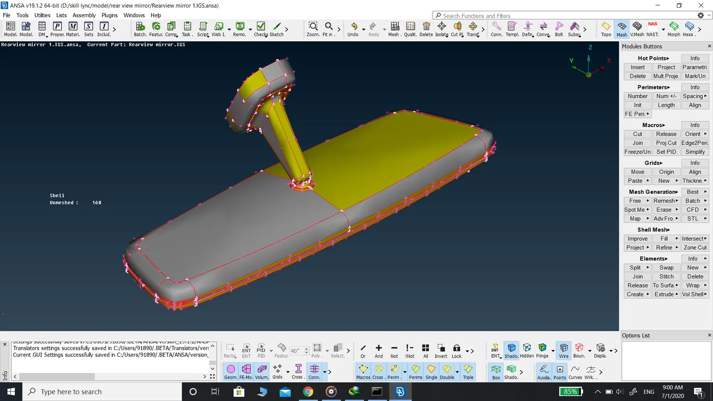
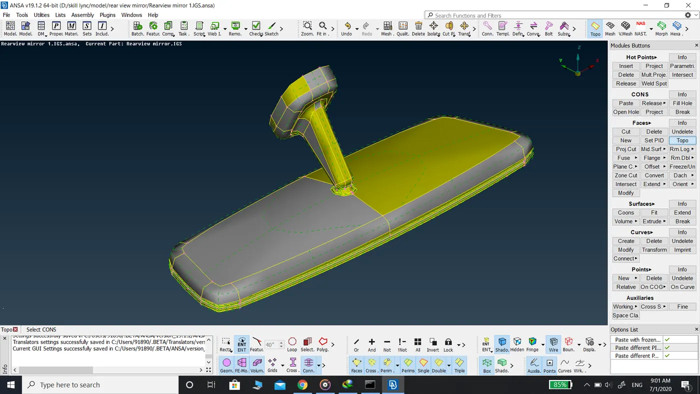
- Once the model is downloaded, topo command is used to connect all the surfaces to make it a single geometry, and geometry check is performed.
- As per the CAE standards model whose thickness cannot be measured or whose thickness is greater than 5mm are recommended for solid meshing.
- In solid meshing, extraction of the mid surface is not possible or complicated. Hence the geometry clean-up is done after topo and no extraction of the mid surface.
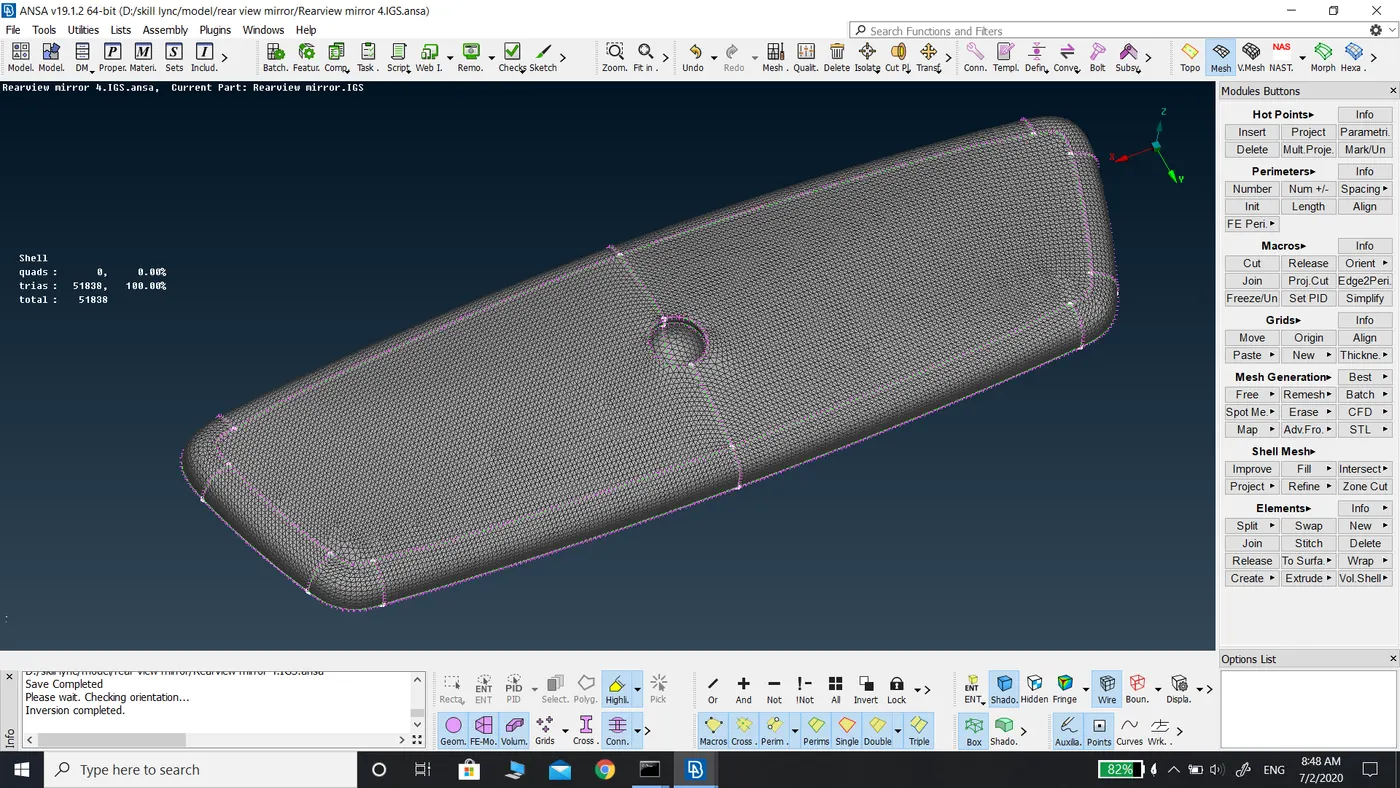
- To capture all the features of the model properly meshing is done with ortho tria type of elements.
- Ortho tria elements are used in the filleted and curved regions to prevent any distortion and to capture the feature in detail.
- Normal tria elements are used in flat surface since there is no varying thickness and hence capturing of feature is done easily.
- Using both ortho tria and tria elements is done to decrease the total number of elements which in turn decreases the computational time and cost.
- Target length of 1 mm is assigned for the model using length command in perimeters in mesh mode to find out any deformations in the given model region by region.
- The model is reviewed area by area to check the perimeters matching the requirements.
- Defeaturing is done to those areas who have a length less than the target length. It is done using the cut command in macros in topo mode. Unwanted cons and cons on straight surfaces are hidden for good mesh flow.
- After defeaturing the component, a geometry check is performed once again for geometrical errors.
- The model is opened in mesh mode and mesh quality is entered in the quality criteria and mesh parameters are also entered.
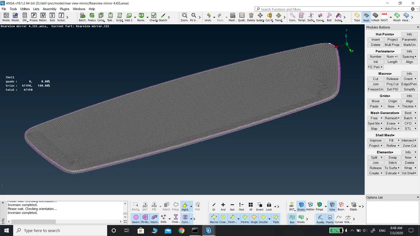
- Meshing is done using Spot mesh with ortho tria type of elements for regions with varying thickness and tria type of element for straight planar surfaces.
- Meshing is done area by area and checked for kinks and dips on the surface of the component. If kinks and dips are found it is removed using reconstruction command in shell mesh.
- After mesh generation for the entire model, the mesh is checked for off elements. If found it is removed by using reconstruction command in shell mesh
- After the creation of shell mesh, the volumetric mesh is to be generated. For the creation of volumetric mesh, the volume should be defined.
- The volume is defined using volumes define command using manual selection.
- After the definition of volume, meshing is done using tetra rapid with the growth rate of 1.2
- After the generation of volumetric mesh, it is checked for off elements in particular tetColapse elements using hidden drawing style.
- The model is reviewed area by area and solved for TetColapse elements using MV free command in grids in mesh mode.
Learning Outcomes:-
- Structured Mesh: This type of mesh is identified by regular connectivity. The possible element choices are quadrilateral in 2D and hexahedral in 3D. This model is highly space-efficient.
- Unstructured Mesh: This type of mesh is identified by irregular connectivity. This allows for any possible element that a solver might be able to use. Compared to structured meshes, this model can be highly spaced These grids typically employ triangles in 2D and tetrahedral in 3D.
- Volumetric mesh desk
- Definition of volume for the model using define command in volumes
- Tetra Rapid: The tetra Rapid algorithm meshes the volume with Tetra Elements. The generated volume elements are connected to the surface mesh of the boundary of the volume. The quality of the generated tetrahedral elements depends on the quality of the shell mesh of the boundary of the volume.
- Tetra FEM: This function automatically creates a Tetrahedral mesh inside elected volumes, initially with pyramid elements if the starting surface mesh contains quad elements. It is used mainly for structural applications.
- Maximum growth rate: the approximate growth factor of the volume element size from layer to layer while the generation moves towards the interior of the volume.
- Maximum Element Length: It specifies the maximum allowable length of the tetra elements to be generated. Useful when specifying growth factor while keeping the length of the elements below a certain value.
Conclusion:
In this challenge, I learned about the volumetric mesh and different types of volume mesh that are structured and unstructured mesh and its features and uses. I was introduced to a volumetric mesh desk for the generation of solid mesh for the given rearview mirror model.
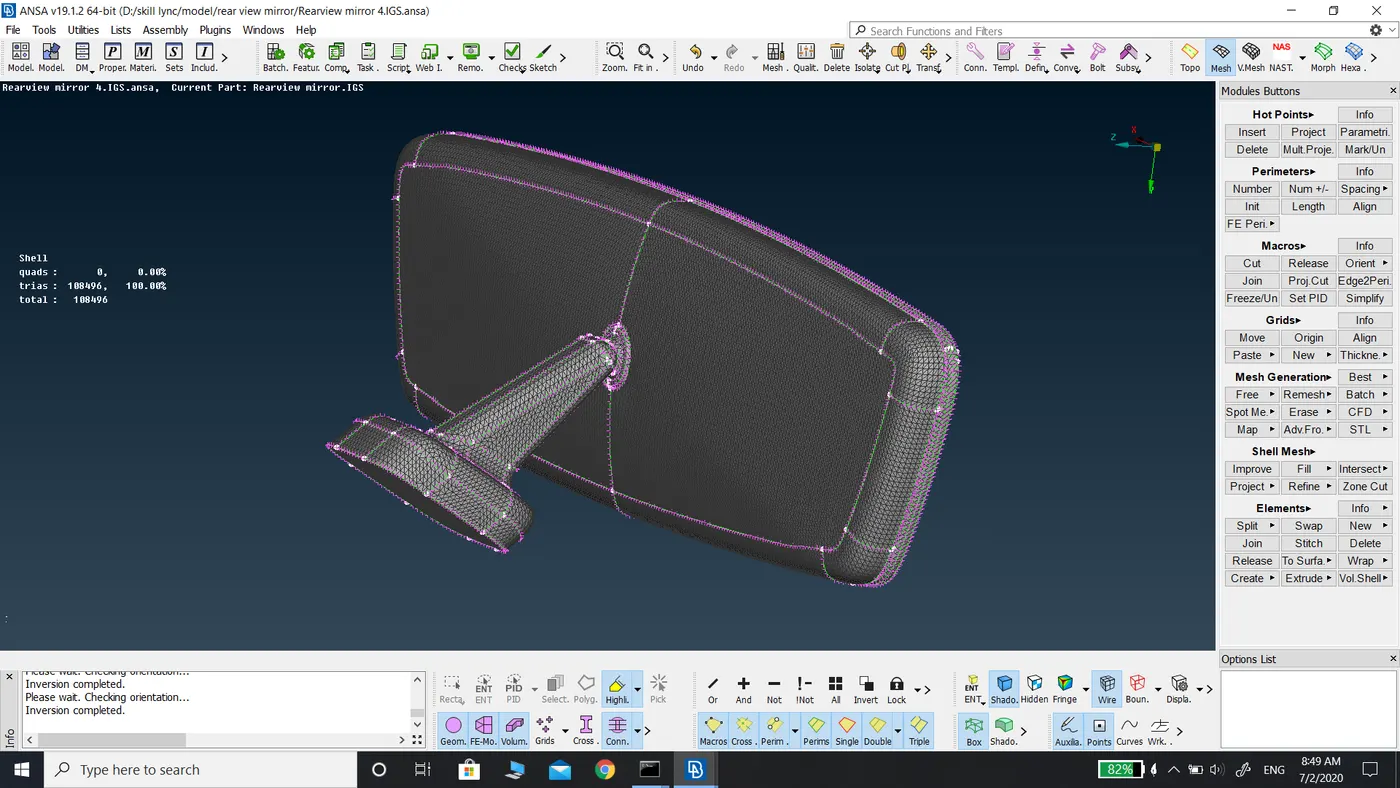
For the Given model total generated mesh elements are
|
Shell mesh |
Volume Mesh |
||
|
Tria Elements |
1,08,496 |
Tetras |
4,62,917 |
|
Off elements |
0 |
Off elements |
0 |
|
Total Elements |
1,08,496 |
Total Elements |
4,62,917 |
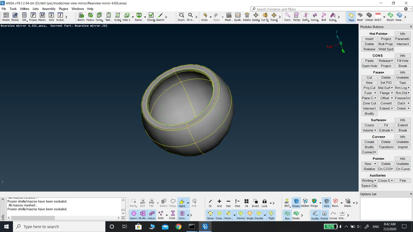
Before Topo
After topo
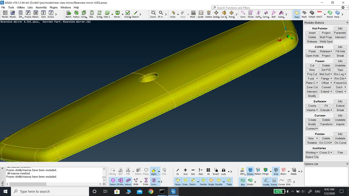
Before Geometry Clean up
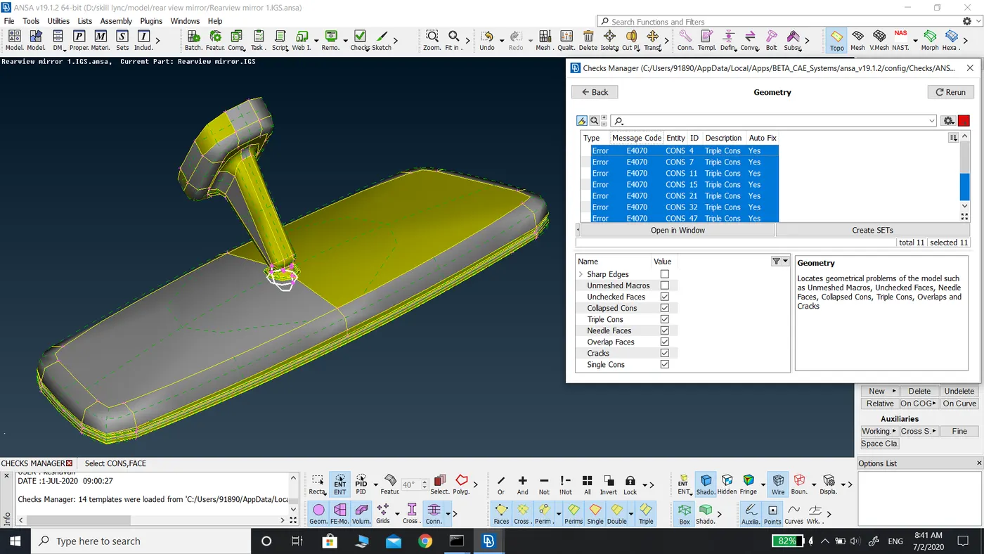
After Geometry clean up
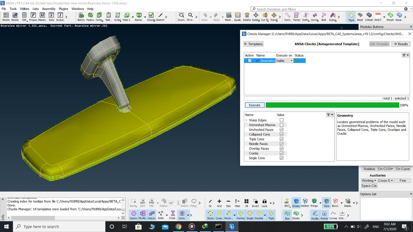
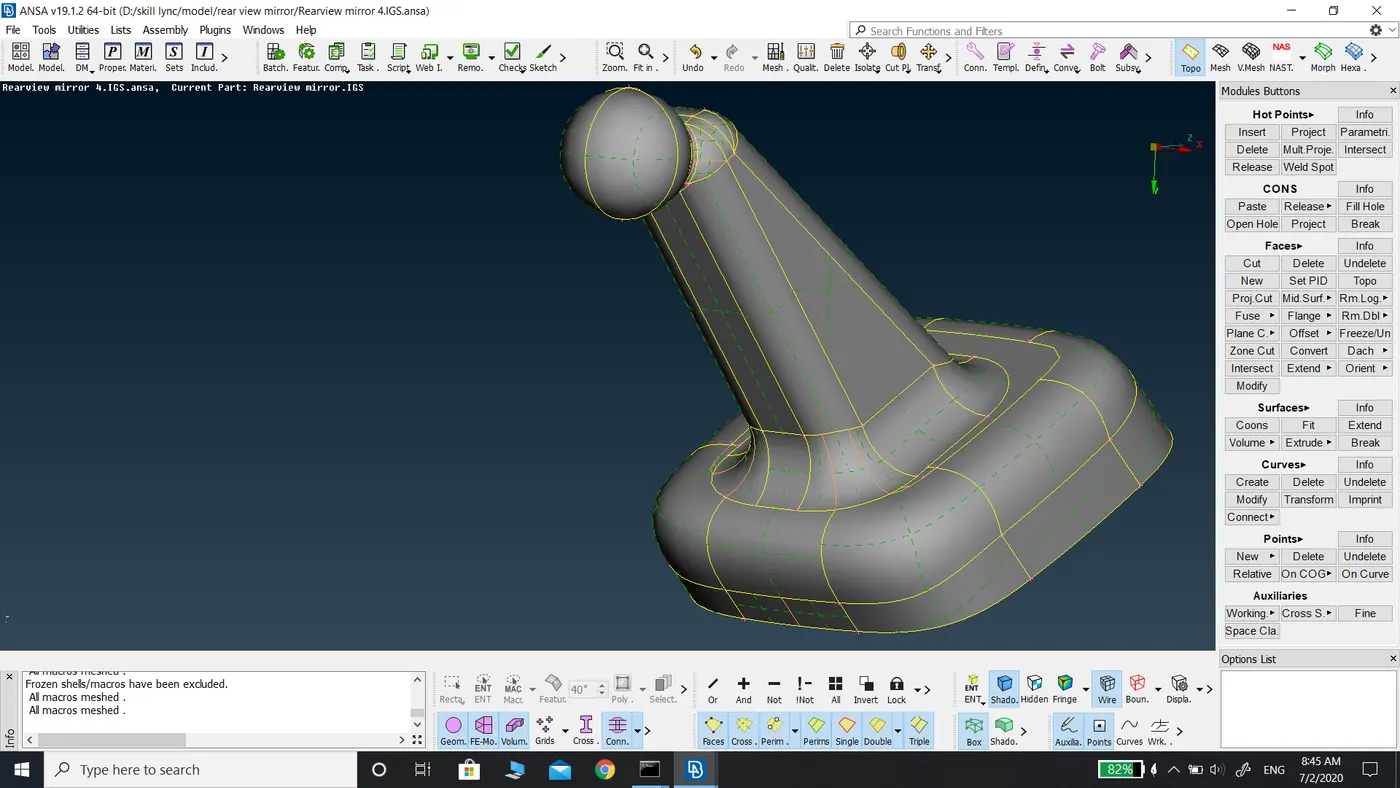
Components in the model before defeaturing
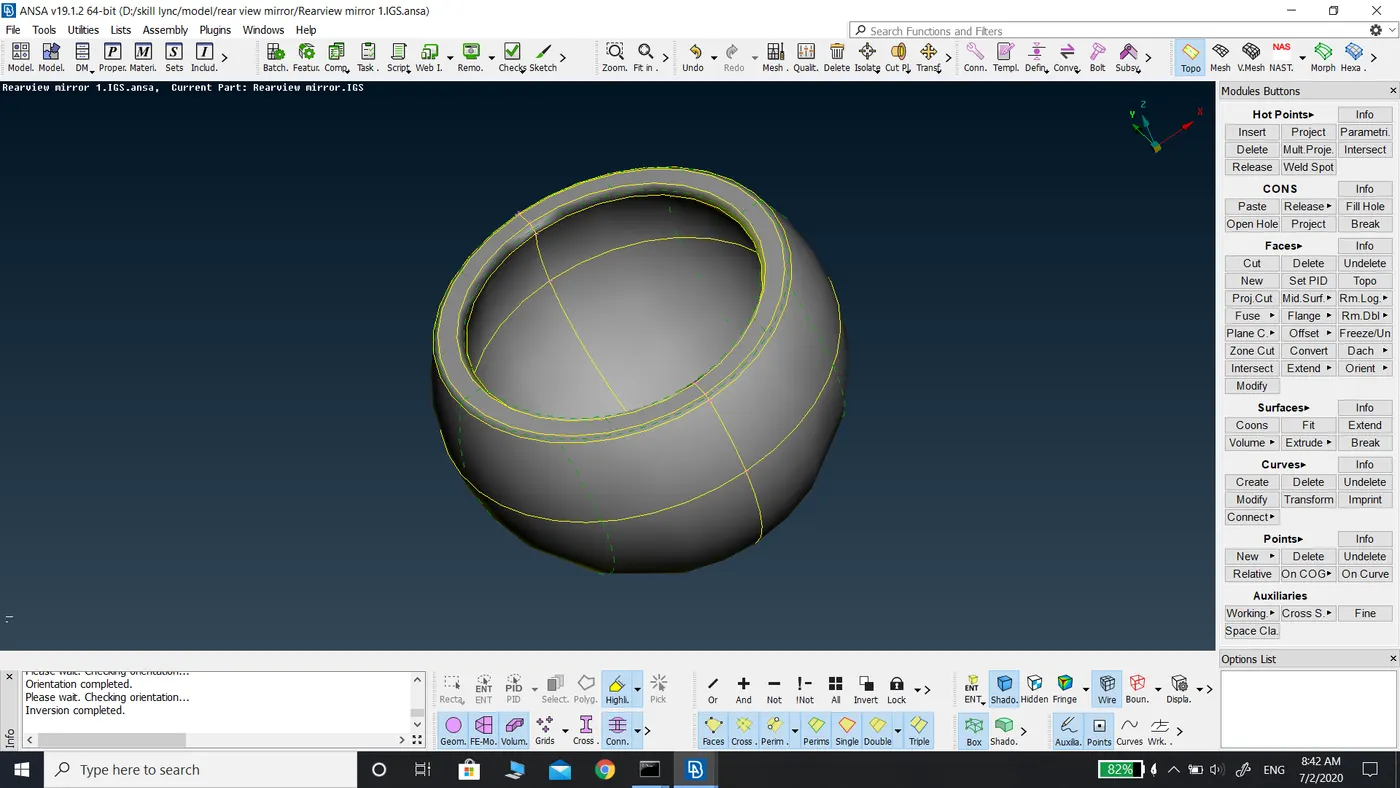
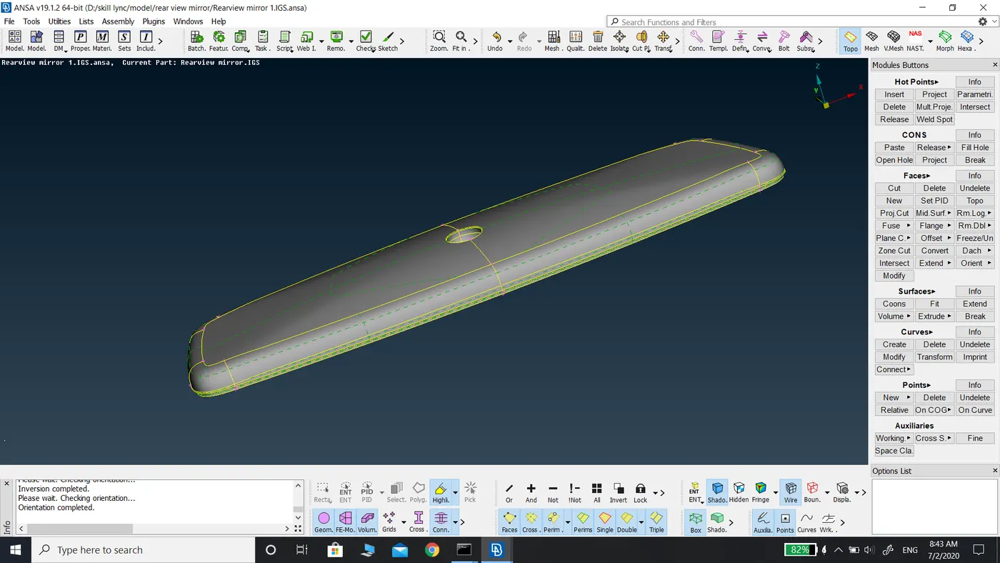
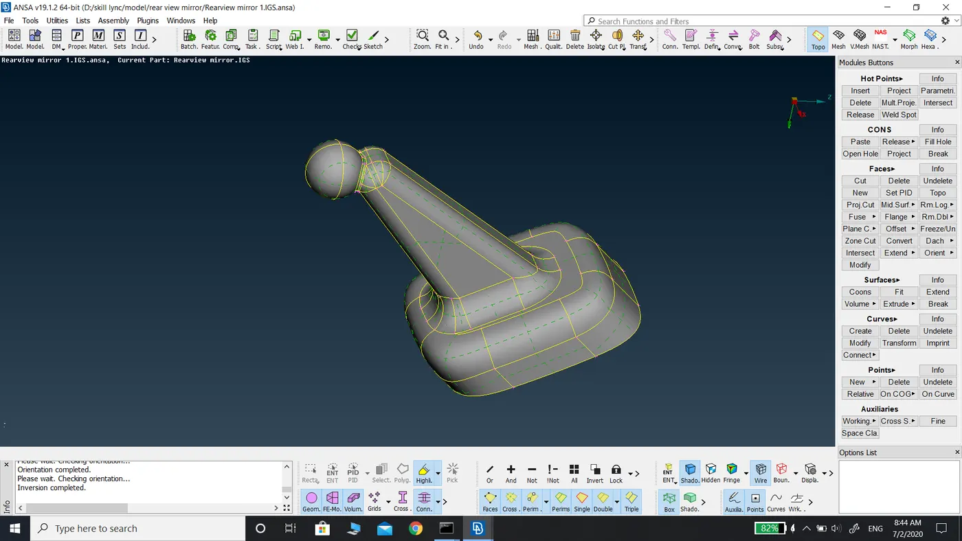
Components in the model after defeaturing
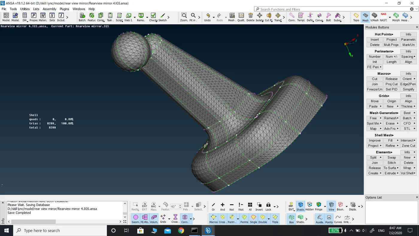
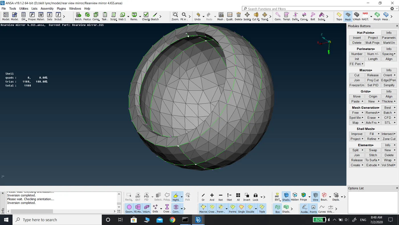
The meshing of the components
The hidden drawing style of the model
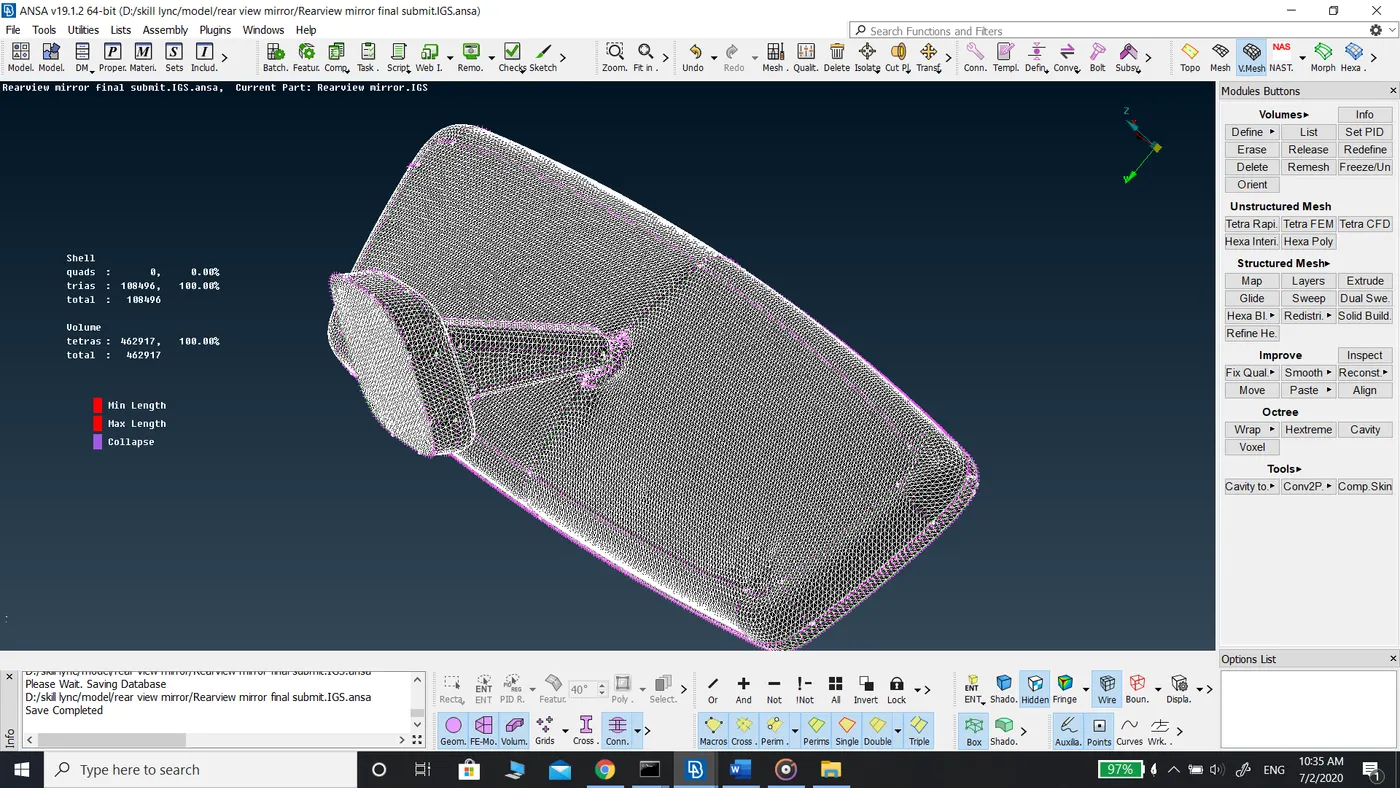
Cross-section of the Volume mesh, meshed with tetra Rapid algorithm