Week 9 - Project - Master Section Development
Procedure To Development Of B-Pillar Master Section
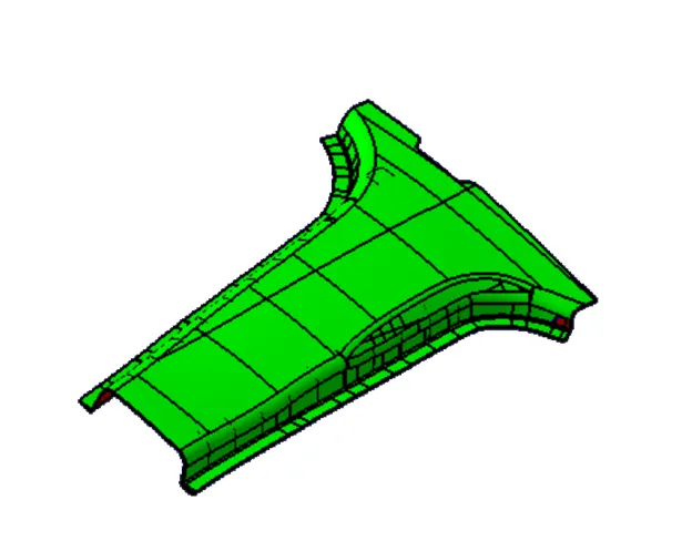
Step -1: - To Develop the master section of a particular component the first step is the visual examination of the part and the final part will like and what are the components included in the particular master section. In my master section it is included with a Dog house and 4way locator for that start with Class-A and Complete Class -B&C and add the Final Dog House and 4Way Locator. Some of the Dimensions are given by the master section. Proceed with that dimension other than that dimensions if any required take from the standard values.
Step -2: - Check the Class-A If any issues of gapes in b/w surfaces or any joining issues in b/w surfaces clear all the issues for the surface by adding multi-section command or fill command depends on the issue get the clear Class-A surface
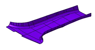
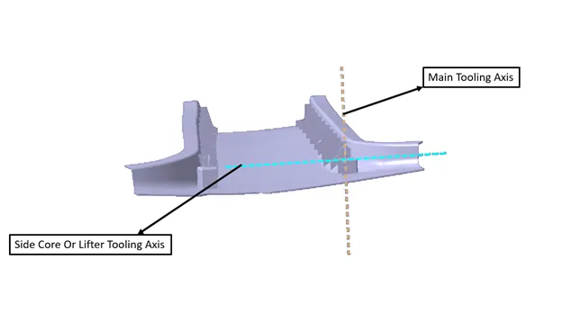
Step -3: - whenever we completed the Class-A the next step is to create the Tooling Axis for the Class-A component for that insert a Geometrical set and name as Tooling References in that another geometrical set name as Tooling Axis based on the master section intersect the two sections there we get a mid-point and use Bisectional method and point as the reference draw a line as name as Tooling Axis.
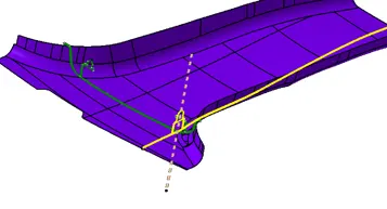
Step -4: - the next step is to create a B-surface for that Off-set the Class-A surface to getting the B-surface for that insert a new geometrical set and name as Constructions in that add another geometrical set name as B-surface off-set the surface up to 2mm and check if any surface is missing from class-A fill the missing surfaces and join the patch surface and Offset surface at the end name as B-surface.
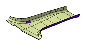
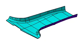
Step -5: - check the master section what are the features that need to add in that section in my case I need to add the Flanges for the Class-A&B for that insert a geometrical set and name as Flanges in the Constructions Geometrical set then use the multiple-extract command and extract the end line or sketch of the class-A where the flange is required and use the Sweep Command “with reference to the surface “ option select the smooth curve and the reference surface enter the angle of sweep and adjust the angle of sweep to the required level and select ok. the sweep surface will generate. Trim the extra surface by using the Trim command and add Fillets for the Flange and Class-A Repeat the same process for the other side
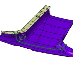
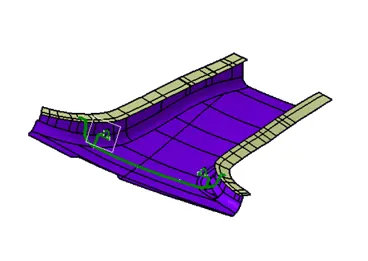
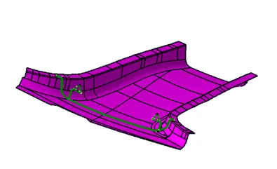
Step -6: - offset the Flanges upto2mm to add with Class-B surface check the surface of the offset flanges if any surfaces are missing or creating any issue fill the surfaces trim the extra surfaces and add fillets for class-A 2.5mm fillet and the for Class-B 5mm and name the Class-A as Class -A with Flange and Class -b As Class-B with Flange.
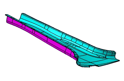
Step -7: - the next step is to create a C-surface to Join Class-A and B by using Tooling Axis for that use the multi-extract for the class -A and the go for sweep command use “with Draft Direction” and select the Tooling Axis is the Draft direction and 3 degrees is the Draft angle extant up to 10mm and repeat the same process for all the boundary surface and trim unwanted surfaces. If any extinction is required to add with side surface use Extrapolate command and trim with the required surface and at the end trim with the Class-B surface then the final B-Pillar Surface was created the next step is to add thickness to the surface for that insert a part body and name as B-Pillar and use Close Surface command to get the solid body
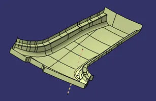
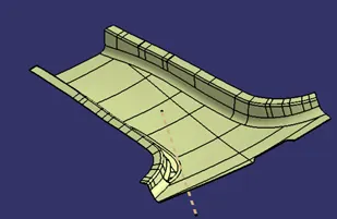
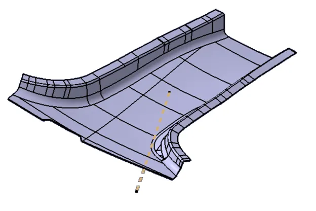
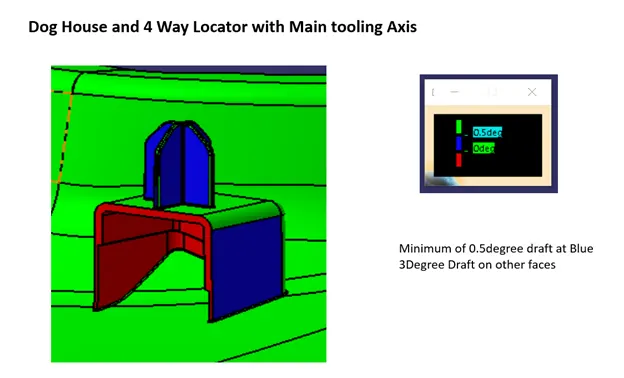
Step -8: -the next step is to add the Dog house for that insert a geometrical set and name as B-side features in that insert a geometrical set name as dog-house and then create a plane with parallel to YZ plane and start sketching on it take a reference sketch from the master section and edit the sketch and use the extrude command and insert a part body in the added thickness of the extrude surface is 40% of the main component thickness that is 2mm
`therefore`0.4 x 2= 0.8mm
Trim the extra parts by using the Split command in the part workbench for adding the B&C section of the Dog house in a general way the height of the B section in b/w 3 to 6mm so I took 3mm as a basic make an offset of the B-surface for the exact the surface and make an offset of 3mm and add the side reference surfaces from the sketch of the dog house and trim unwanted surface for c section 0.8mm for that offset the final offset b-section surface up to 1.2mm and use the split command and remove from the main part and use the union trim command to add the dog house to the B-pillar and add the draft of 0.50 and fillets of minimum 0.3 radii for the dog house
`therefore`0.4 x 2= 0.8mm
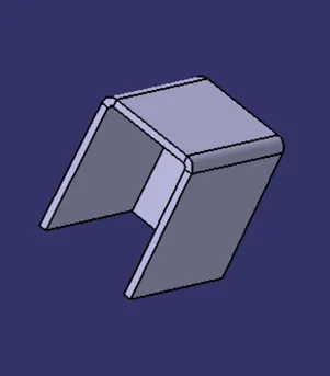
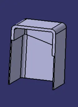
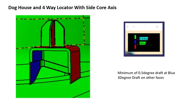
Step -9: - that next step is to add the 4way locator for that take a reference from the Master section and that makes as a sketch and of insect lines use Pad command with a required height of master section and the thickness of 1.5mm from neutral axis and add a draft of .50 and for the faces add to the Dog house with union trim command to add some feature on the next side copy the component and use Symmetry option to get the same component on another side
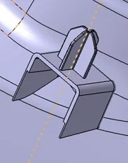
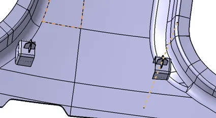
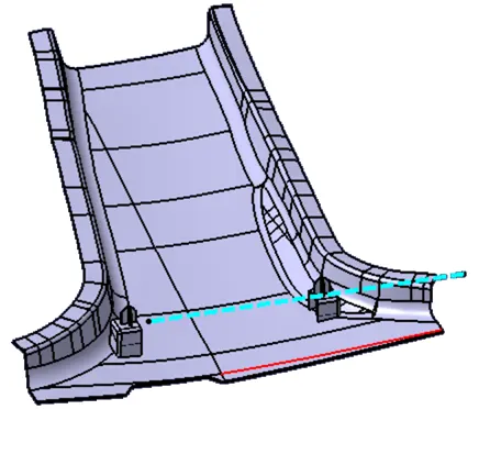
To add draft to that Dog house need to add the Side Core Tooling axis or the Lifter axis for the select the midpoint of main tooling axis and select the direction as X-axis . and name as Lifter tooling axis
Step -10: -once the Dog house and 4way locator was completed and added to the main component the next step is to add the supporting features of the component like Ribs to create the Ribs insert a geometrical set and name as ribs and start sketching in it distance b/t the rib is 50mm and draw a line with that dimension and add the number of ribs that can be inserted in the component. exit the sketch and extract each line separately and use extrude the line that can covers the top and bottom part of the component and then insert the part file and use the thickness command and add the thickness of the extruded surface to get the top trim off-set the class-B surface up to 10mm and use Split command and remove the unwanted features and then make all the extrudes in the same procedure and add into Rib-1 Part file use unitrm remove the unwanted faces and add to the B-pillar repeat the same method to the other side ribs.at the final step add the Draft to the Ribs and fillets as well.
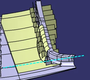
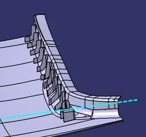
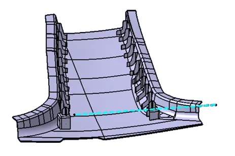
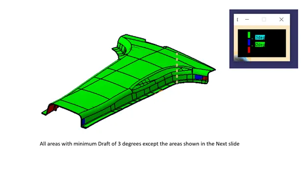
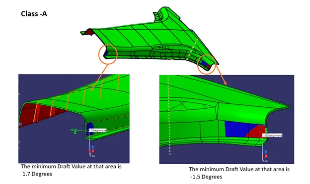
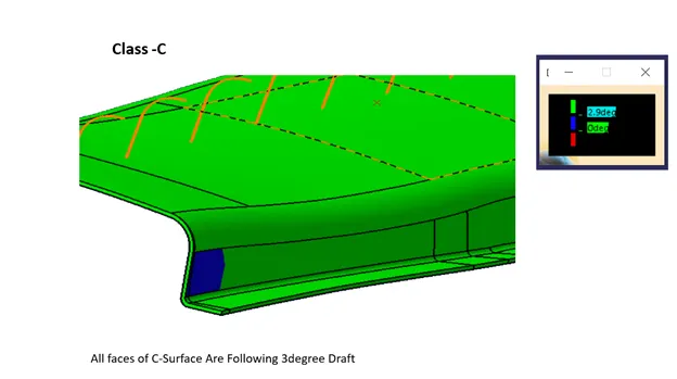
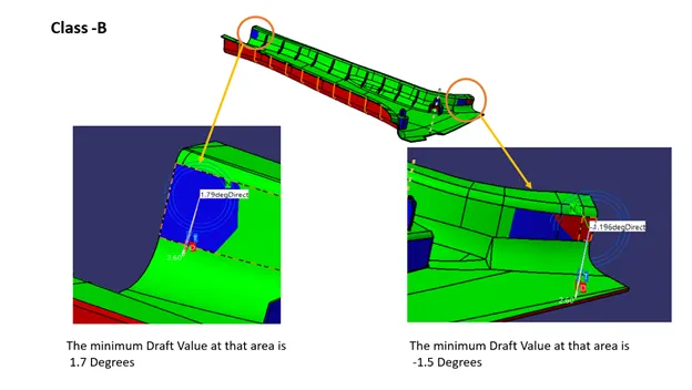
Step -11: -After adding all the features to the b-pillar check the Draft analysis of the final components are there any issues in the component is to change for the final manufacturing all the features are clearing the tooling directions or having any issues.id the issues are related to Class-A or in the master sections report the issue with the respective department and clear the issue
Draft analysis in the part-work bench there is a direct option named with Analysis in that we can select Draft analysis .
Images of B-pillar
front view
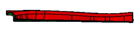
Top view
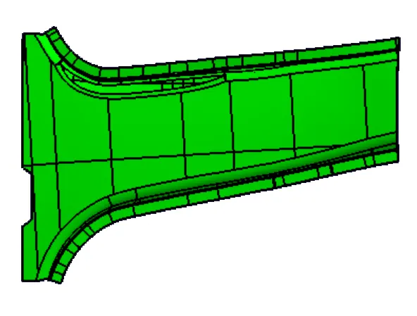
bottom view
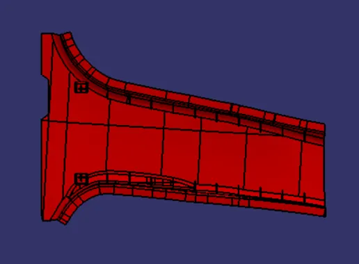
right side view
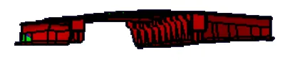
left side view
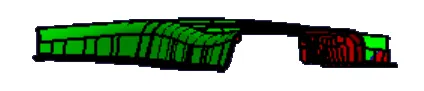
iso