Week 9 - Project - Master Section Development
DESIGN OF B-PILLAR MASTER SECTION
AIM
To Create a Solid Body of the B - Pillar from the input provided as the class A surface and attachment features for fixing the component at appropriate position with the main component following the OEM design standards using CATIA V5 software.
INTRODUCTION
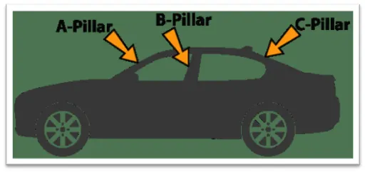
B- Pillar
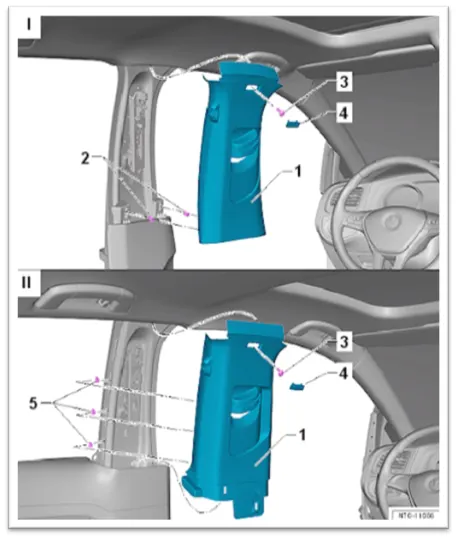
- The B- Pillar is the central pillar of the car. This pillar is actually a sheet metal part which is welded in the BIW of the car. The B - pillar Trim is attached to the B - pillar and improves the Aesthetic look of the car. Mostly the trims are manufactured by the injection molding process. the design of the B-pillar is carefully done to make the part manufacturable and usable in the interior. while manufacturing a part through injection molding a lot of defects can occur on the plastic part which will destroy the look of the panel. The design has to make in such a way that all the errors can be rectified.
MASTER SECTION
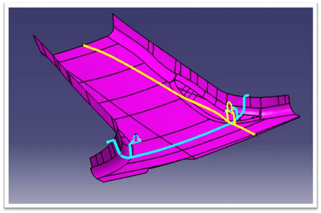
- Master Sections are the guides for design requirements which shapes. The component after Technical Styling of the Class A Surface.
- The body frame is mainly composed of floor longitudinal Beams, Upper side beams, Door sill beams and front cover, the rear beam, A-pillar, B-pillar, C-pillar and other Load bearing beam structures are composed.
CLASS A SURFACE
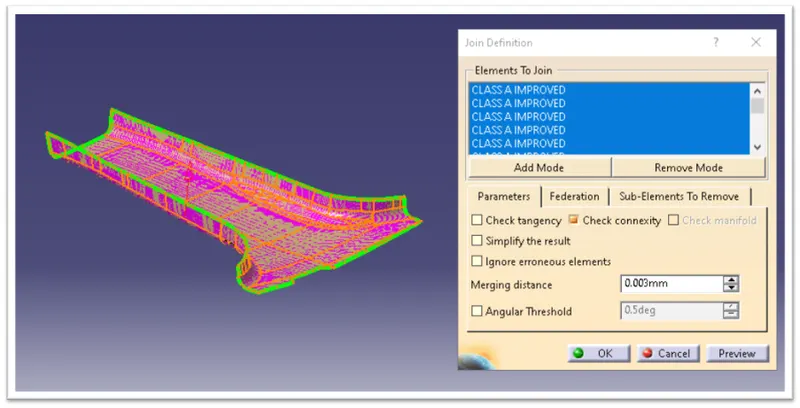
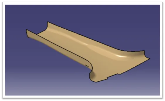
- Before we start creating the closed body for the B-pillar. we need to check the quality of the given A surface. The A surface needs to be free of all the patches or error elements. For this first, we need to disassemble the given styling surface and join it with the merging distance of 0.003mm.
TOOLING AXIS CREATION
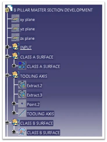
- A reference point is created along the surface zero and new axis system is created.
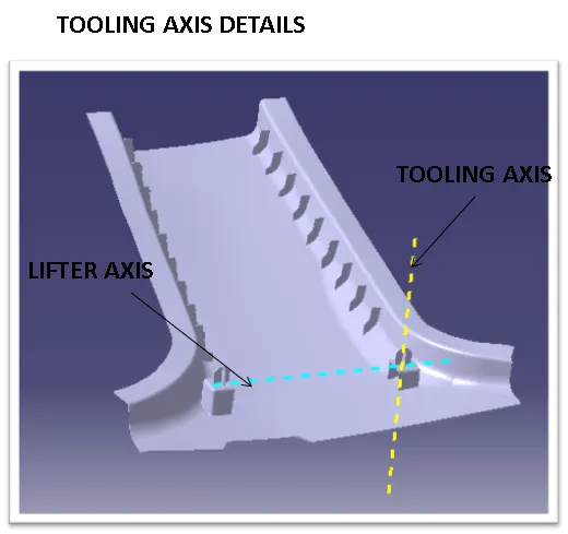
- The X direction and Y direction along the class A were used to create Tooling direction.
- Finally the tooling axis is created by bisecting the two lines and it is published. class A surface as input using surface operation commands class B is developed.
- The tooling axis determines the direction of the class C boundary swept with draft direction.
- When viewing from tooling direction normal all the parts that are drafted should be visible so it gives an rough idea to determine product manufacturing in injection molding.
- In B pillar model there are two tooling directions one on main tooling and other on lifter side that is used to eject the parts during injection molding.
- Lifter axis is used because the attachment feature is bounded by close walls.
CLASS B SURFACE
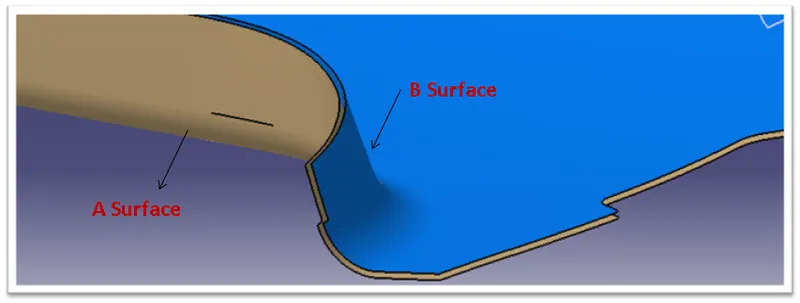
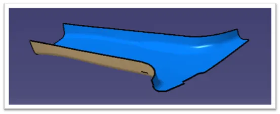
- The next step is to design B surface for the input which is usually the surface where all engineering aspects and support creations are done.
- The B surface creation is performed using surface operations in catia which is an offset from class a with dimension proportional to the thickness of the part
- In B pillar design the B surface is offset 2mm from the input which is the thickness of the part.
FLANGE CREATION
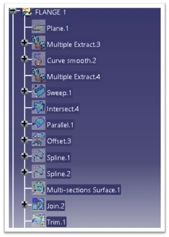
- According to the master section, The B-pillar has Flanges on both sides. The Flanges have to be included in the design and the A and B surface has to be modified. The surface should match the master section.
Main Tooling Axis Creation:
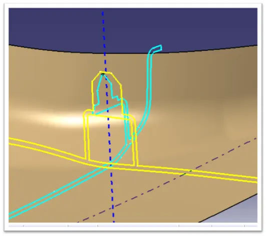
- The Tooling Axis is the Direction in which the Core Moves. During Injection Molding the core is moved into the cavity and molten plastic is injectwd. When this molten plastic is cooled Down then the core is moved Away from the cavity. The direction in which the core moves is the Tooling direction for the part.
- To find the Tooling Direction WE Use the Mastersection for the Engineering Feature. Here We take the two boundaries and find a bisecting line between them.
DRAFT ANALYSIS OF A SURFACE:
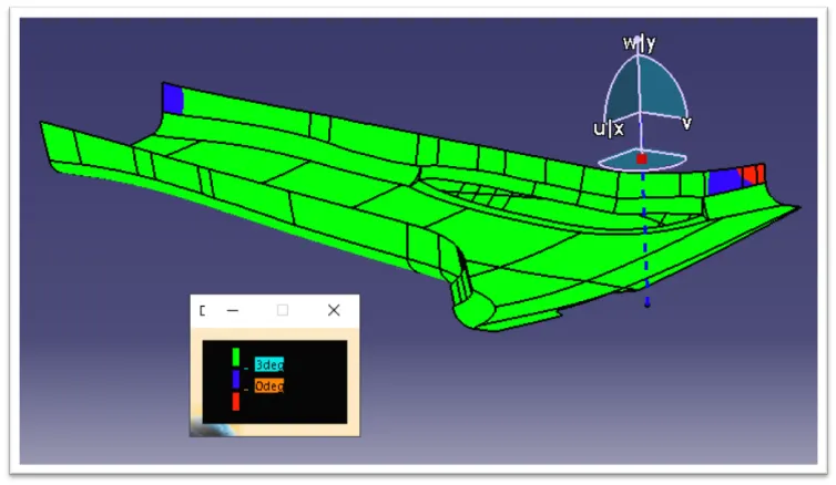
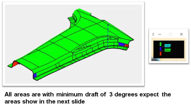
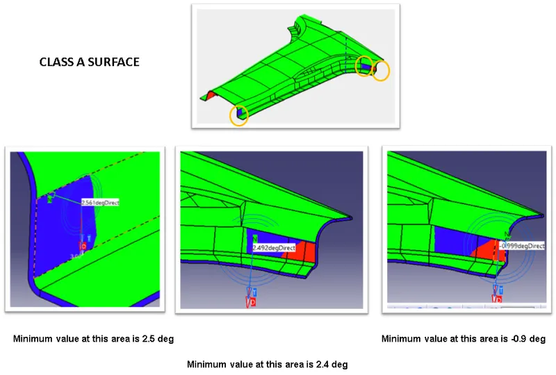
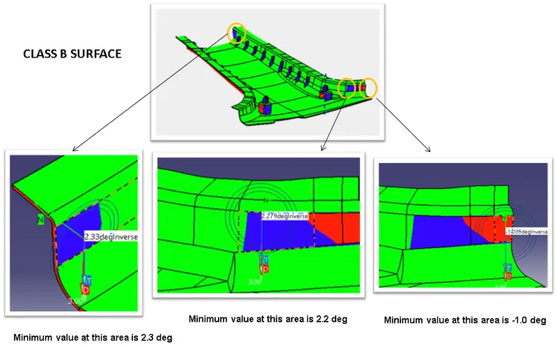
- Draft Analysis is used to check the A-surface manufacturing feasibility. The tooling axis is used as a reference. Draft Analysis checks the angle at which the surface is with respect to the tooling axis. As we know for injection molding the draft on the surface should be positive and greater or equal to 3 degrees. Areas with the draft less than 3 degrees are a bit difficult and costly to manufacture.
CLASS C SURFACE CREATION
- The Next step is to from the C surface which is an intermediate surface between A and B and is used to give the Closed surface appearance to the design.
- The C surface is swept using the profile as boundary line of class A which is the Guide curve with a subtype along draft direction.
- The direction of the sweep is the tooling direction formed earlier.
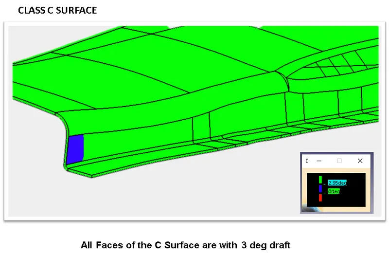
- The Draft angle for the sweep operation is provided which is 3 degree and surface is swept for length above the thickness of the specified part.
- The C surface must be drafted outwards from the A side to avoid the parting line along the A surface.
- The C surface is refined using smooth curve options to remove the compllexity and patches along the swept surface.
- Finally the class A and C surface are joined together and connexity of surface should be less than 0.003mm And the surface are merged. C surface Merged with Class A
Closed Body Creation:
- The merged surface is then trimmed with B surface to Form the closed surface.
- The Closed surface is then validated to find the irregularitirs along the edges and imperfections along the edges were then corrected using operation like extrapolate and surface trim.
- This closed surface is the ouer skin and finally the part is formed by closed surface in part design workbench.
- The final part is measured to validate the uniform thickness of the part especially along the filleted edges.
- The Uniform thickness ensures that the part created doesnt form sink mark and flow lines along class A.
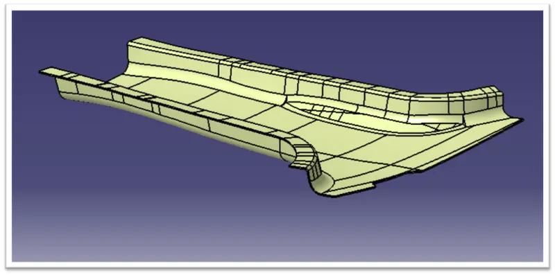
- Closing surface at angle of 3 degrees with respect to Tooling Direction.
ATTACHMENT FEATURES
- The Attachment features are the fixation and location features that fixes the components the common attachment features used in B pillar Are,
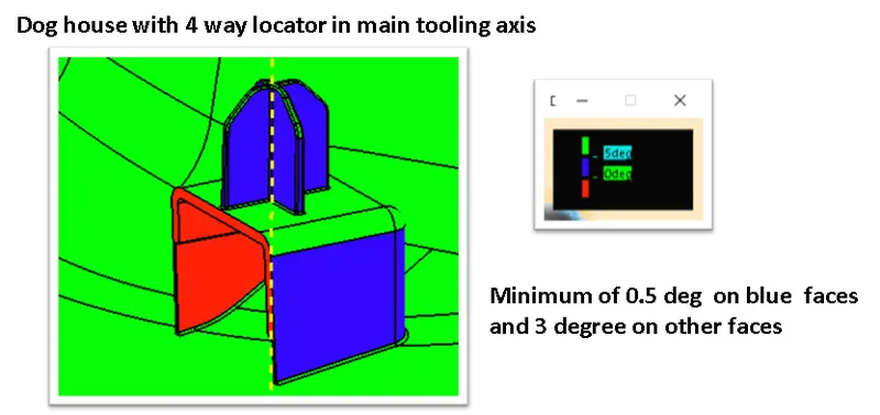
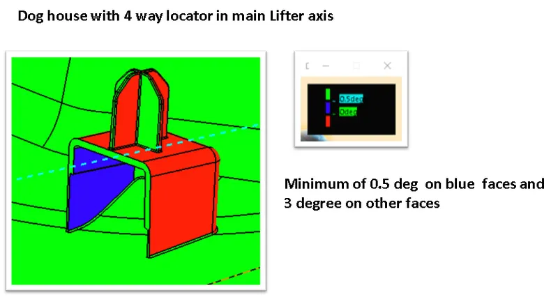
- Doghouse with 4 way locator
- Ribs
DOG HOUSE
- Using the Master section the doghouse is created and then part modelled using thickness option
- The 4 way locator is formed above the dog house which locates the B pillar towards the mating surfaces.
The Dog house design rules Are,
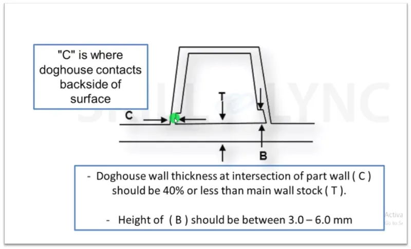
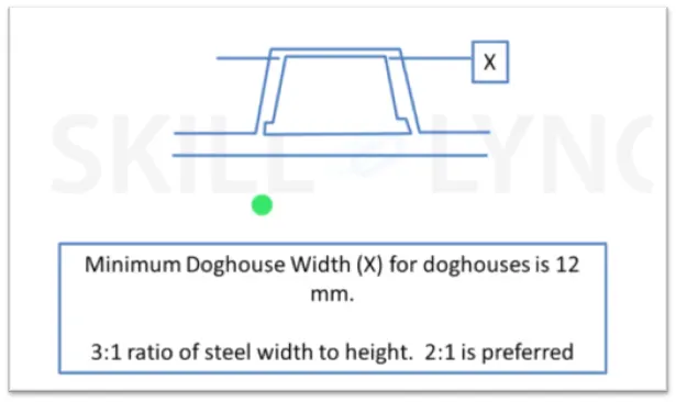
The doghouse with four way locator are shown below
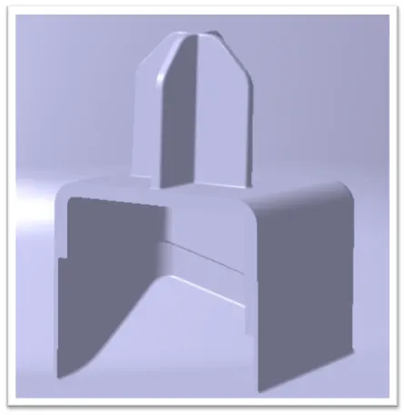
- Four way locators are Tapered along the edges to create an entry point for locators and the locator walls are drafted along the main tooling direction.
- The walls are minimum of above 0.4 times of the total thickness to avoid shot apex walls are ensued to enough for creation of parts.
RIBS
- Ribs provide stifness to the parts and can be to impart thougness without increasing the part thickness and are locators and provide allignment to the mating parts.
The Design Rules for two Way and Four Way locators:
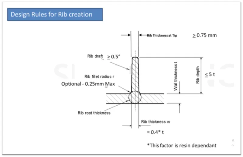
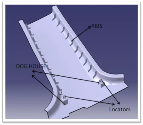
- In B pillar the rib are 50mm apart on both sides.
- Thus B pillar cover is surface development is completed and attachment features are added.
- It should be noted that the fixation of the bolt locators always follow 3-2-1 Taylor principle.
- Translational Movements long X,Y, Z Axis (positive and negative)
- Rotational Movement along X,Y,Z Axis (Clockwise and Anticlockwise)
- The Improvement in given B pillar Could be an addition of another Dog House at an Extreme end to satisy the Taylor's Principle and thermal stakes are provide that arrests all degrees of freedom and completly fits the B pillar part.
DRAFT ANALYSIS PROCEDURE
- The part created has to be changed to material mode in display frame.
- Then by Enabling compass definition the axis system is pan along the direction of the part and Aligned in line with the Tooling Direction.
- Lock direction is aoolied that Fixes the compass and then the mode Dialog box is formed by snapping at any point on the part.
- The color codes are classified and draft angle are applied.
- Then the running point analysis is used to hover around the part to analysis the permissible draft angles and the analysis is saved.
DRAFT ANALYSIS REPORT
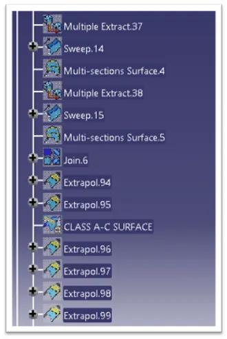
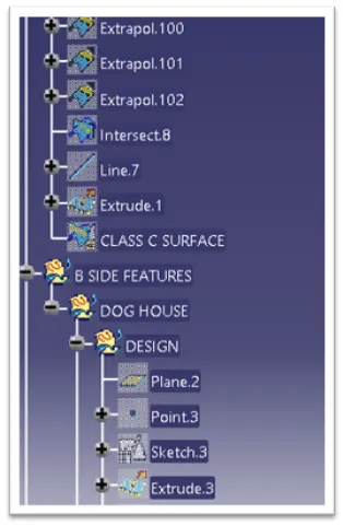
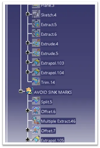
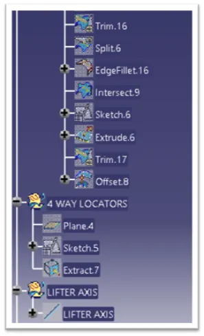
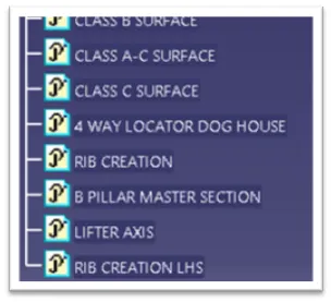
TREE STRUCTURE
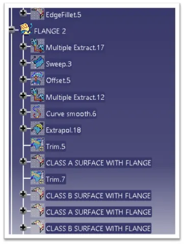
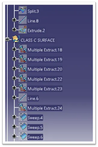
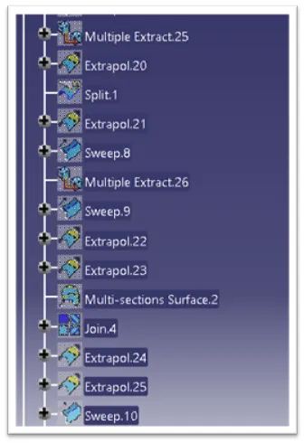
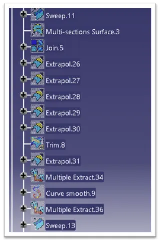
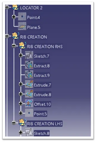
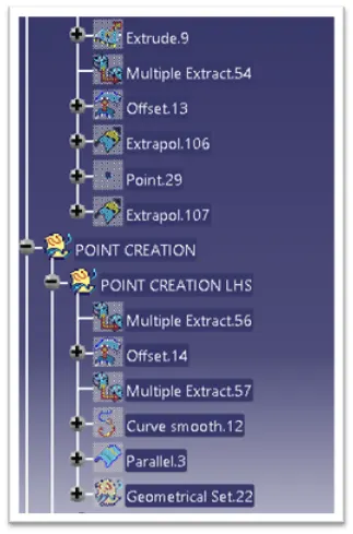
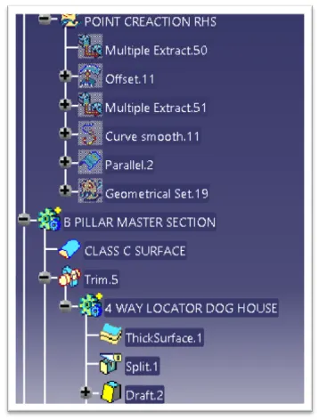
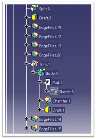
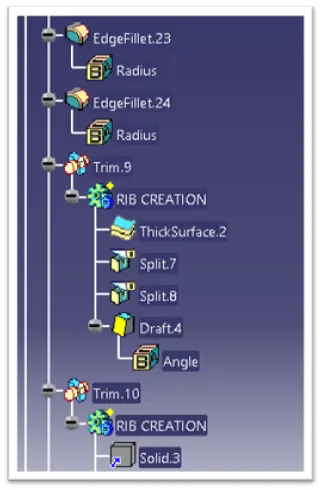
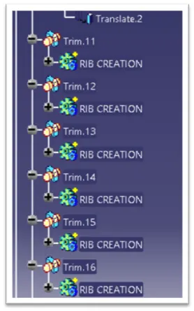
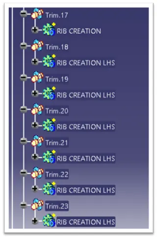
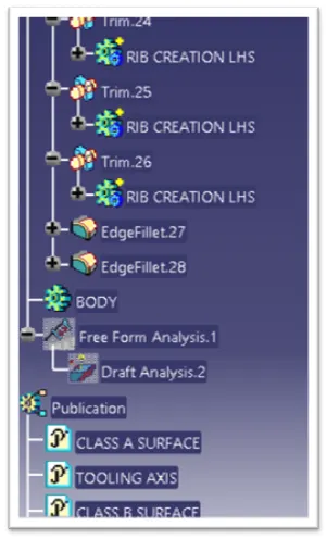
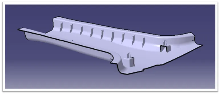
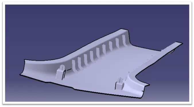
ISOMETRIC VIEW
CONCLUSION
- Thus a Tooling Axis is created and a open aesthetic class A surface is developed into a closed surface with all plastic design rules and a final part body is created out of it in catia surface workbench. The design is then validated with master section and understood the use of master section development in product design through development of B pillar cover used in the car interiors.