Week 8 - Challenge 2 - Base Bracket Design
DRAFT ANALYSIS OF A BASE BRACKET
AIM:
To Create the Base Bracket Plastic component through the given Class-A surface. To begin with, the tooling axis for the given Class-A Surface should be created meeting the requirements of the draft angle and also Create the Class B Surface & Class C Surface. At the end perform to give thickness of the model.
DRAFT ANALYSIS:
- Draft analysis is performed based on color ranges identifying zones on the analyzed element where the deviation from the draft direction at any point, corresponds to specified values. Draft is required on all parts in the direction of mold movement in order to allow parts to release or eject from the properly.
- Draft is the angle in which the parts is tapered to allow it to release. As the part cools, it tends to want to shrink to the core side of the mold. The draft allows the parts to release easily from the mold without creating friction between the surface of component and the core and cavity plates.
- Most applications require minimum draft angle of around 5o to 1o, however 3o draft angles are widely accepted for cost saving purpose. 7o draft angles are given to textured surface like instrument panels. Minimum possible draft angles are given to screw bosses, ribs and stiffeners due to their critical nature.
PROCEDURE:

1. CLASS A SURFACE:
In automotive design, a class A surface is any of a set of freeform surfaces of high efficiency and quality. Class A surfacing is done using computer-aided industrial design applications. Class A surface modelers are also called "digital sculptors" in the industry. Industrial designers develop their design styling through the A-Surface, the physical surface the end user can feel, touch, see etc.
Design check on Class A Surface:
- After reciving class a for the BASE BRACKET check for the connectivity of the surface on it. If there is any disconnectivity, use join operation, multiple extract, multi section surface, boundary operation and disassemble.
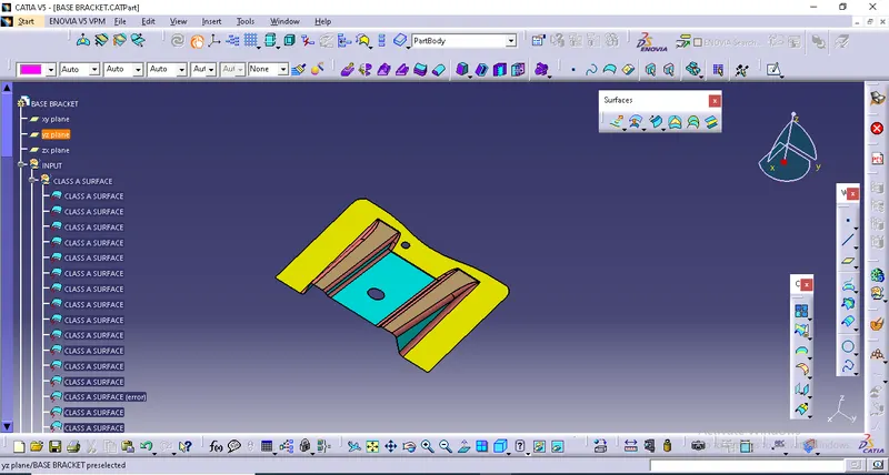
Join operation:
- Go to join command to join the disconnectivity of the surfaces.
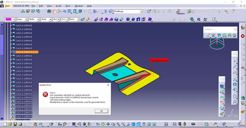
- If any surface not connect due to Topological error. To follow the below step for joining and then click "ok".
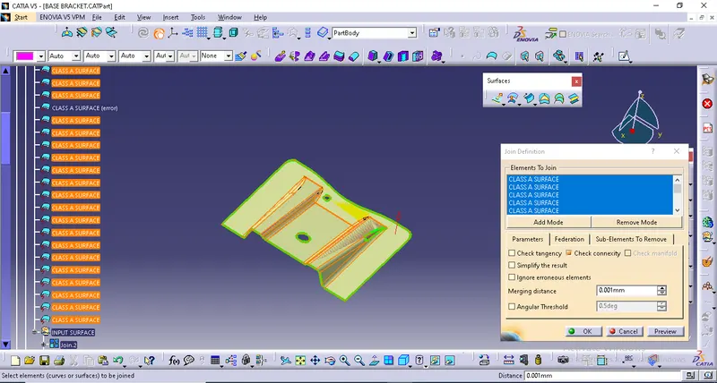
- Use Multiple Extract command for error surface and then click "ok".
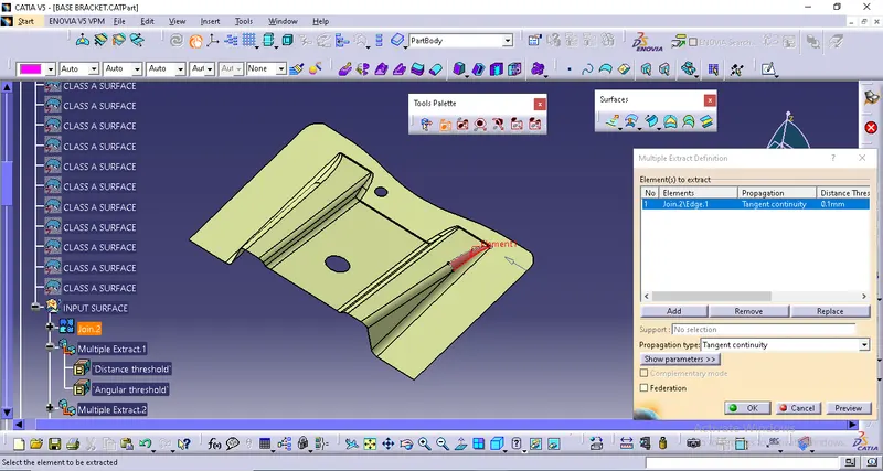
- Use Multi Section Surface command for joining the Multiple Extract lines and then click "ok".
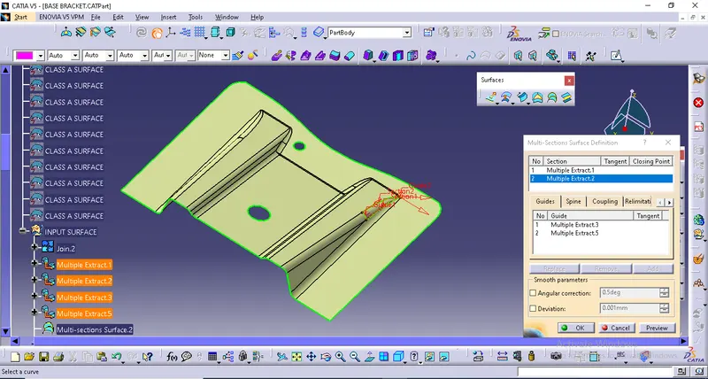
- Join.2 & Multi section surface.2 profile to join using join command, then click "ok".
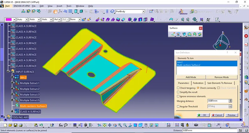
- When there not connected, after reciving Class A surface, delete only the checking command of boundary operation and disassemble, When there are connected delete join operation, boundary operation and disassemble after the check. The check is over if any disconnectivity do not arise.
2. TOOLING AXIS:
- It is the dirction in which the mold open or core & cavity open. Part drafts are given along this axis.
Tooling operation:
- To deside the tooling axis, the component should be completely clearing the Tooling axis in the given specific direction. Analysis the components, the fan cover components has two walls.
- First one visually check. We can check, which one is possible to Tooling Direction. We can check al x, y & z direcion. If you have hole, what it will happen, you haven separate side core for specific hole. In this draft analysis of fan cover Z – direction is the possible of Tooling direction.
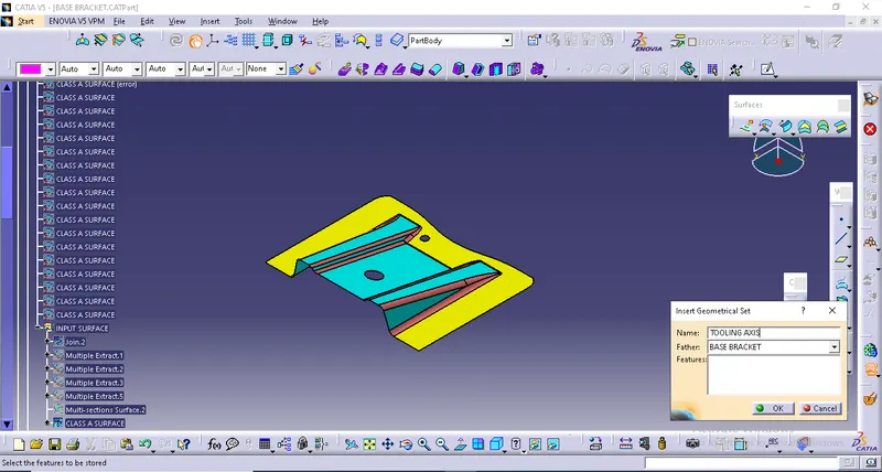
- To create the boundary for hole.
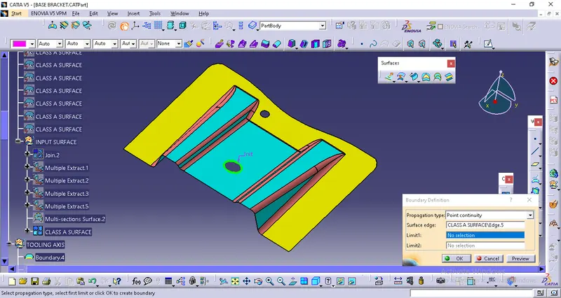
- To create point on the position sketch. Making sure that all faces are clearing the Tooling.
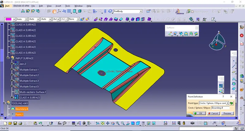
- The represent has a base bracket to solve the tooling.
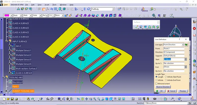
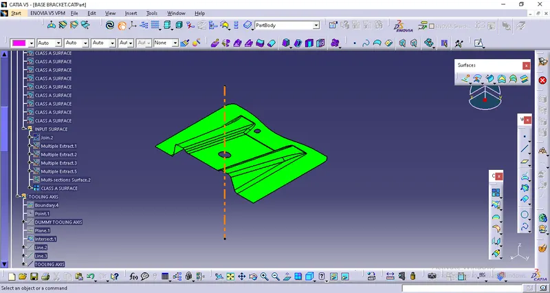
- We consider z direction, draw line approximately to Tooling direction to help to visualize the Tooling.
- This is called Dummy Tooling direction. Along with z direction all the faces should along with z direction.
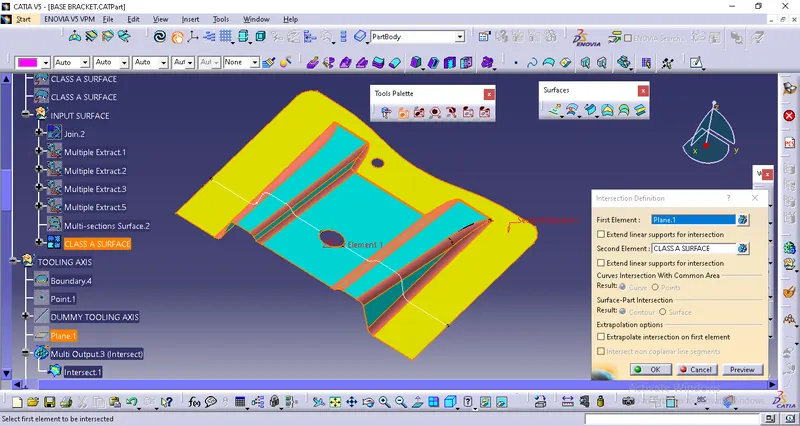
- To create Plane along yz direction,For Intersection command through y-z plane as a result it get two profile.
- To create line on which two points along with both two sides.
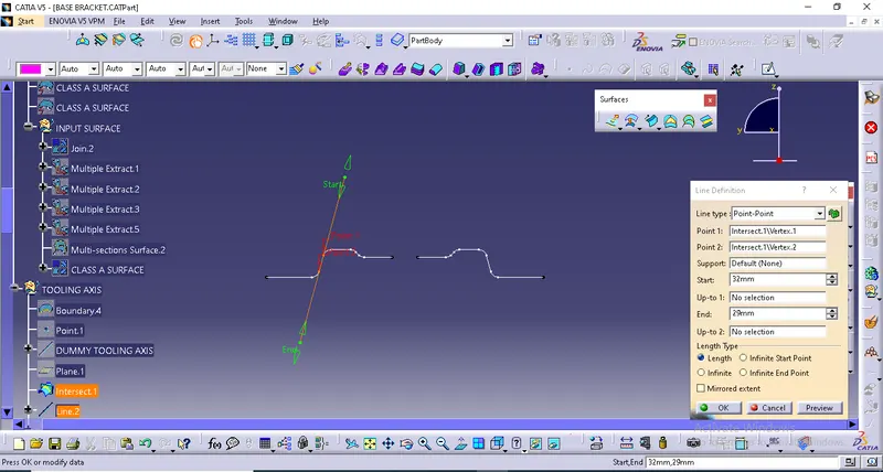
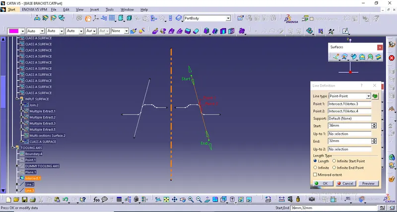
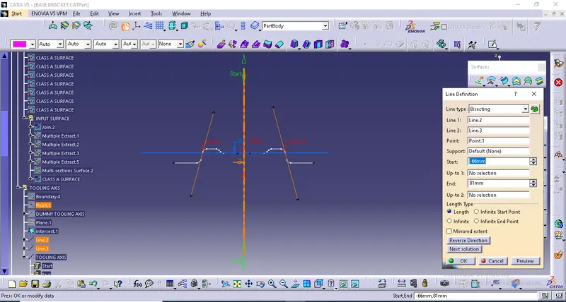
- Create bisecting line for the extended line along the center point on both the line and name it as Tooling Axis.
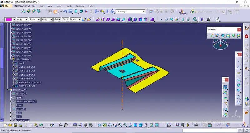
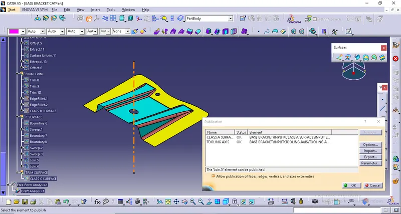
- Publish it using INSERT – PUBLICATION – Select the Class A Surface & Tooling Axis.
- To make sure that easily visual to work on draft.
3. DRAFT ANALYSIS:
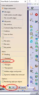
- Change view mode
 customize view parameters.
 - Choose the material in shading option.
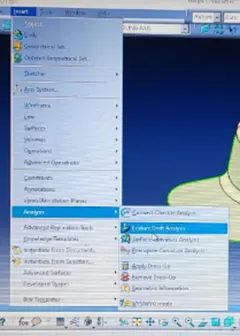
- Go to INSERT – ANALYSIS – FEATURE DRAFT ANALYSIS.
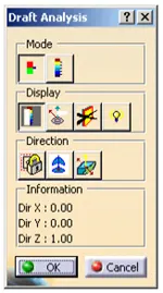
Commands are to be used during Draft Analysis operation:
- The Draft Analysisdialog box is displayed. It gives information on the display (color scale), the draft direction and the direction values.
- The Draft Analysis.2dialog box showing the colour scale and identifying the maximum and minimum values for the analysis is displayed too.
Mode operation:
- The mode option lets you choose between a quick and a full analysis mode. These two modes are completely independent.
- The default mode is the quick mode. It simplifies the analysis in that it displays only three colour ranges.
- Double-click on the value in the colour scale to display the Value Edition dialog box.
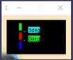
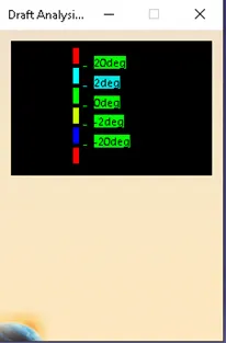
- Enter a new value (negative values are allowed) to redefine the colour scale, or use the slider to position the distance value within the allowed range, and click OK.
Display Mode:
- Uncheck the Colour Scale
 checkbox to hide the Draft Analysis.2 dialog box, this dialog box only appears in edition mode.
 - Activate the On the fly
 checkbox and move the pointer over the surface. This option enables you to perform a local analysis.
 - Arrows are displayed under the pointer, identifying the normal to the surface at the pointer location (green arrow), the draft direction (red arrow), and the tangent (blue arrow). As you move the pointer over the surface, the display is dynamically updated. Furthermore, circlesare displayed indicating the plane tangent to the surface at this point.
- The On the flyanalysis can only be performed on the elements of the current part.
- Click the No Highlight Representations
 button to set the display option of highlight effect sources as "on/off". When checked "On" the surfaces are selected but they will not be seen in the specification tree.
 - Click the Light Effect
 button and the colours of the analysed elements react to the light source.
 - Click the Inverse
 button to automatically reverse the draft direction.
 - Click the Compass icon
 to define the new current draft direction.
 - Click the Locked direction icon
 , and select a direction (a line, a plane or planar face which normal is used), or use the compass manipulators, when available.
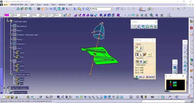
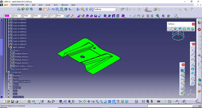
- Once you have finished analysing the surface, click OK in the Draft Analysis dialog box.
4. CLASS B SURFACE:
- To the value of the thickness of the component to get B Surface. It is a surface it gives thickness from Class A Surface, all the engineering features like screw bar,ribs and other supporting features could be form on the B Surface. In other tream Class B Surface know as Engineering Surface.
Surface operation:
- To create the thickness of the class A surface along with the following steps.
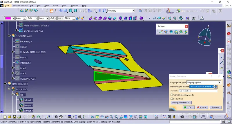
- To create rib of the base bracket by using Extract command.
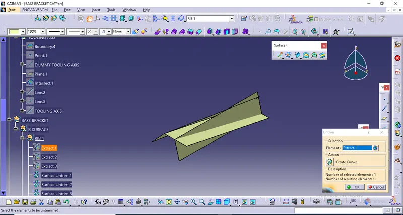
- To Untrim the all of Extract profile.
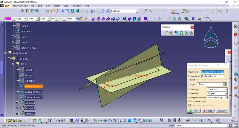
- To Extrapolate the untrim profile for given values.
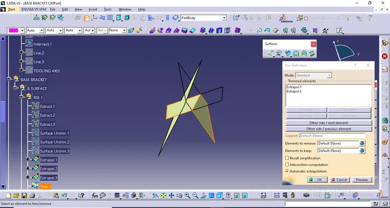
- To trim the Extrapol profile in need position.
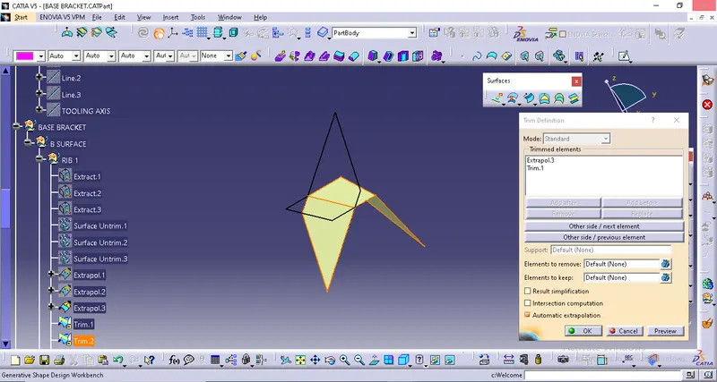
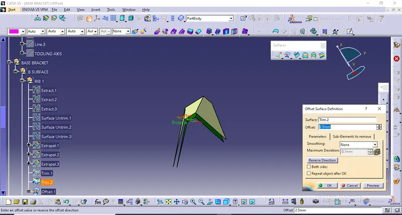
- To give thickness value of offset command.
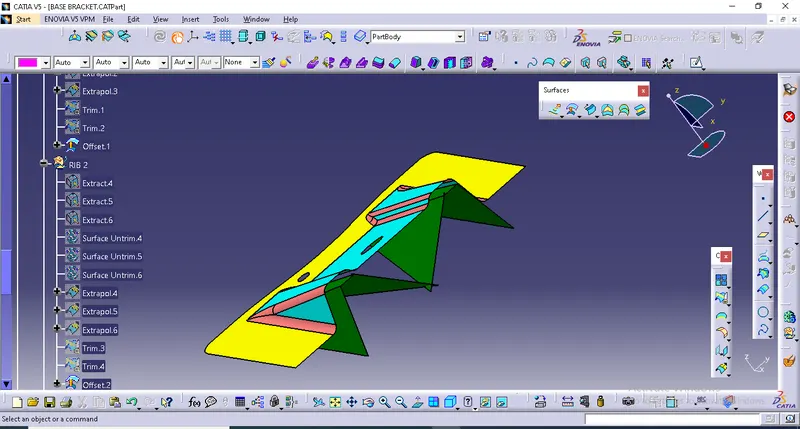
- The above rib.1 procedure is similar with the rib.2 and base bracket.1 creation.
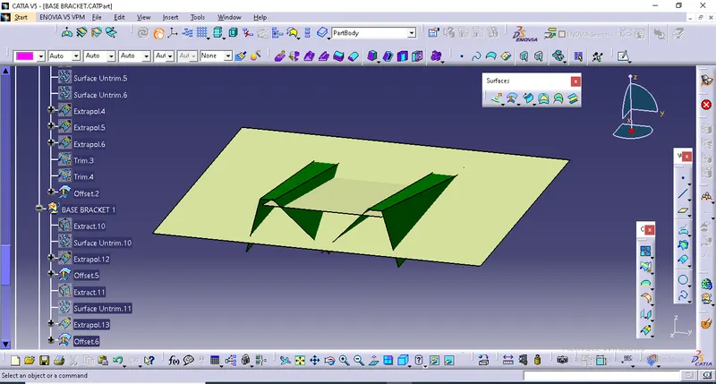
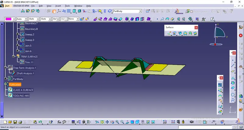
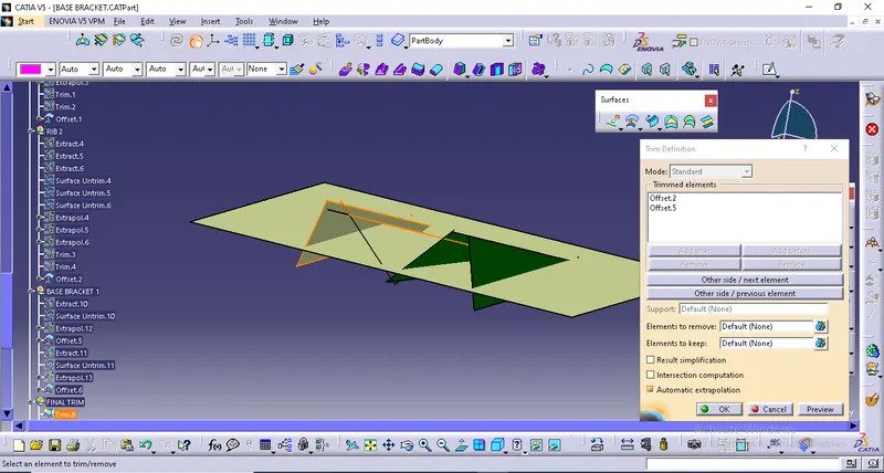
- The final steps to trim the profile of offset.2 and offset.5
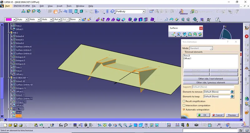
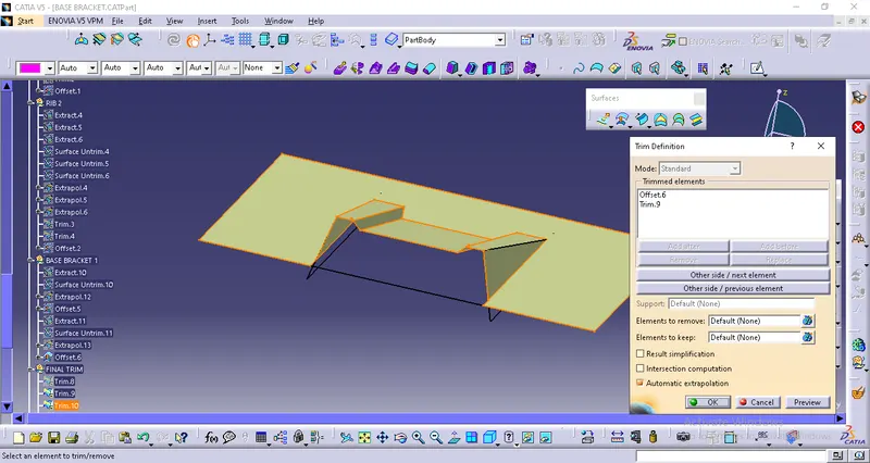
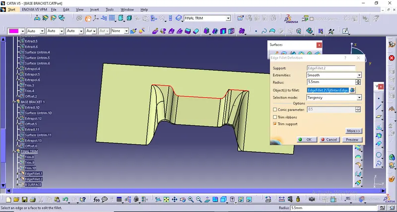
- The final steps to trim the profile of offset.6 and trim.9 .
- To give the correct fillet values to avoide sharp edges.
5. CLASS C SURFACE:
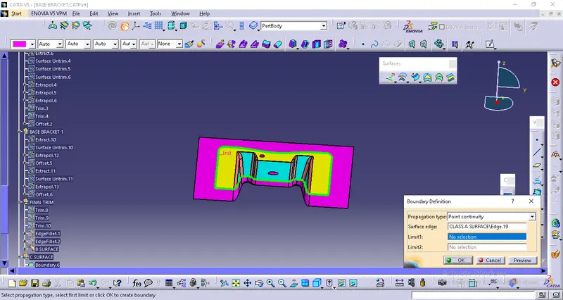
- The purpose of Class C surface is to connect Class A surfaces & Class B surfaces.
- It gives thickness of the model.
Surface operation:
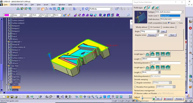
- To help of sweep command it create some thickness of profile.
- Also sweep the holes in the surface model.
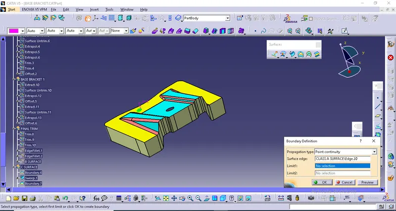
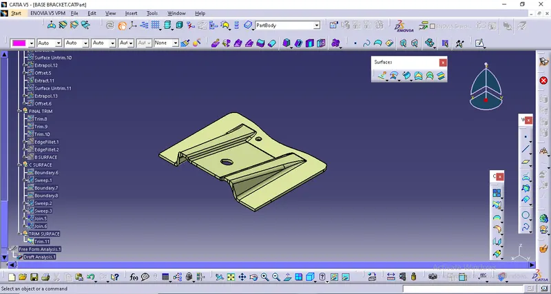
- The final step of Class C surface, to trim the Class C surface & Class B surface.
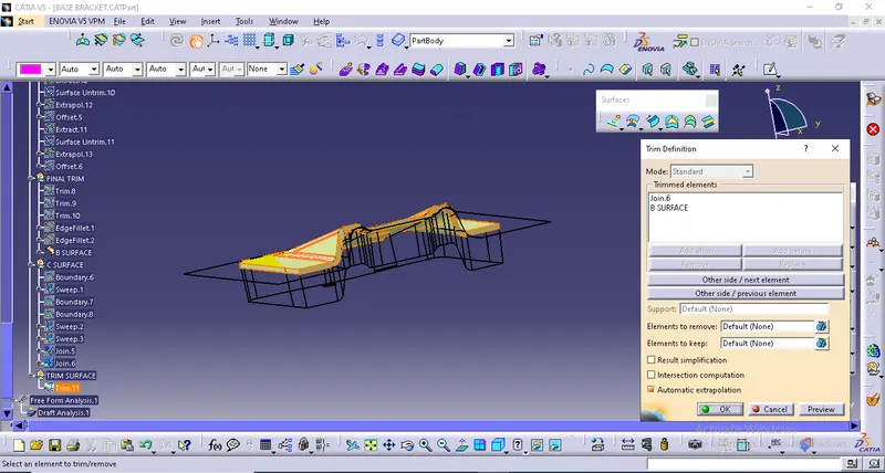
- The below figure is known as Class C Surface.
6. CLOSE SURFACE:
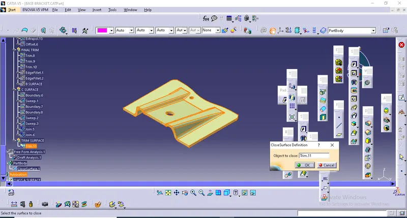
- Close surface is alos known as thickness of the model.
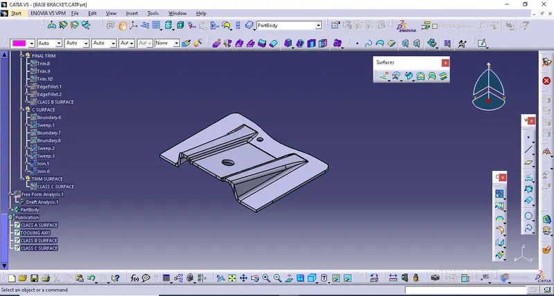
- go to part modeling & click the close surface option it create complete model of surface.
CONCLUSION:
At the end of this model, we can get the complete profile of base bracket, also the thickness of the component.