Week 9 - Project - Master Section Development
Aim:- The Aim of the project is to create a solid model of the given class A surface of the B pillar by applying the design rules.
Objective:-
- To create a tooling axis on the class A surface so that we can perform the draft analysis on class A surface and the solid part.
- To create the class B and class C surface using the class A surface.
- To get the final solid closed body from all the surfaces.
- To create the B side features for solid body.
- we need to plublish the class A, class B , class C , Final solid body and the tooling axis.
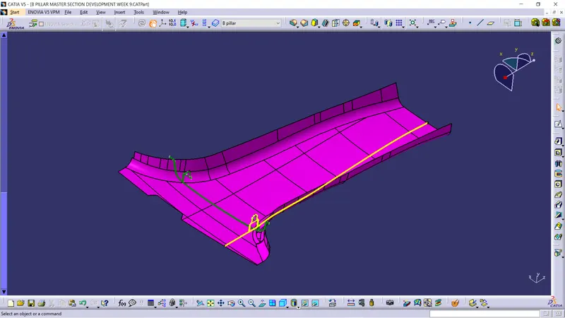
Given B pillar class A surface.
Tooling Axis:-
Here first we will discuss how the tooling axis is created for the give class A surface
- First we extracted the line of locator at four sides in the master section.
- Next the point is created in between the middle lines.
- We drawn the bisecting lines for two opposite line using the middle point and we get two bisecting lines for four lines.
- We get a final bisecting line from that two bisecting lines and that line is the TOOLING AXIS for the given class A surface.
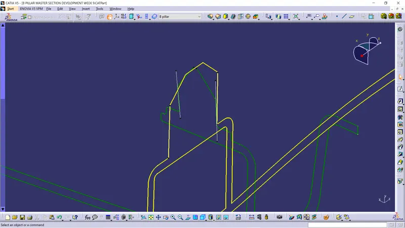
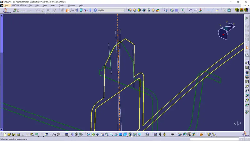
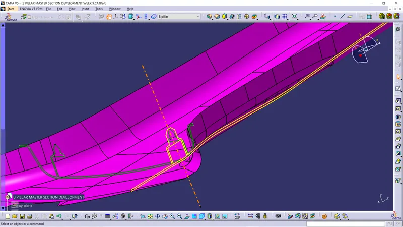
Tooling axis of the class A surface
Draft Analysis along the Tooling Axis :-
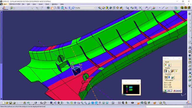
- Draft analysis was performend on the class A surface along the tooling axis to analyse if the given component is toolabe along the tooling dircetion.
- Feature draft analysis option is used to perform the draft analysis on the surface.
- Compass is placed on the created tooling axis using the option in draft analysis ,next the surface is chosen to perform the draft analysis.
- We take maximum of 3 degree of draft angle for the surface.
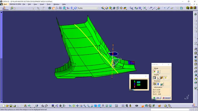
Draft analysis performed on class A surface.
B Surface creation:-
In creation of B surface we just offseted the class A surface because their is lot of complications in the class A surface.
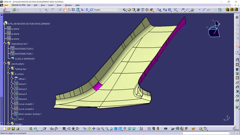
After offsetting the surface we got some patch on surface and we need to correct it.
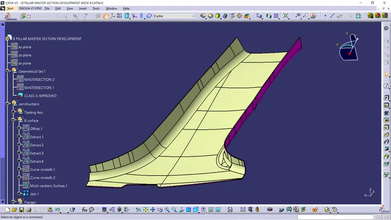
By using multi section surface we fill the gap and join both of them and we got our final B suface.
Flanges creation :-
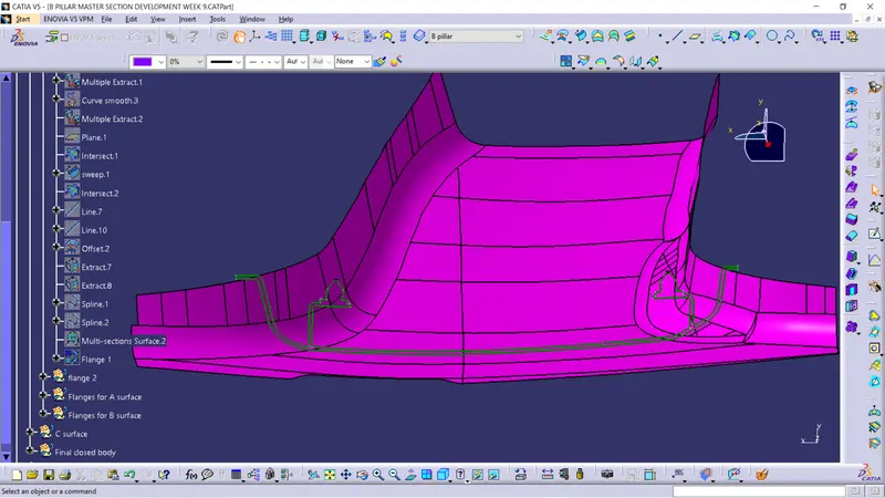
For the given class A surface the flanges are not given so we need to create the flanges for the class A surface.
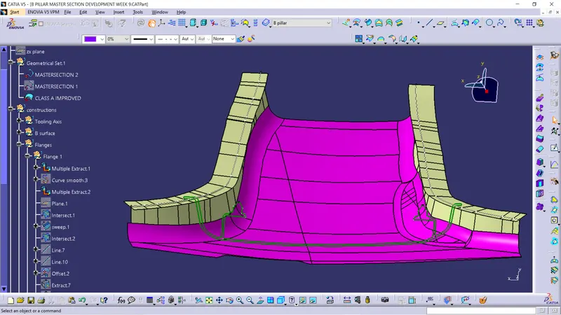
We extracted the side walls and line for the wall and sweep the line by using reference with the surface.
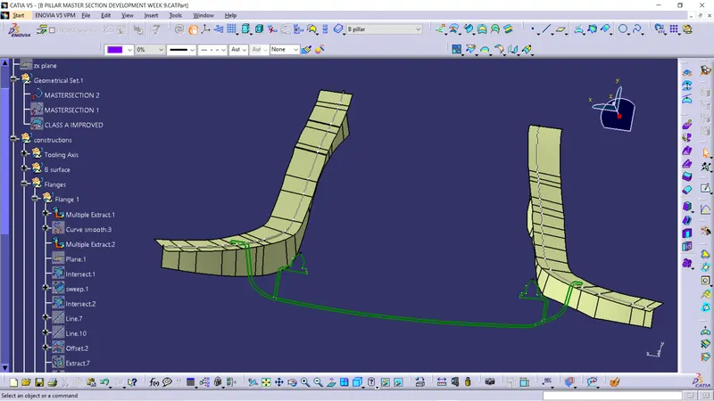
We sweep an angle according to the given mastersection.
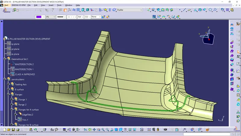
This is final class A surface with flanges.
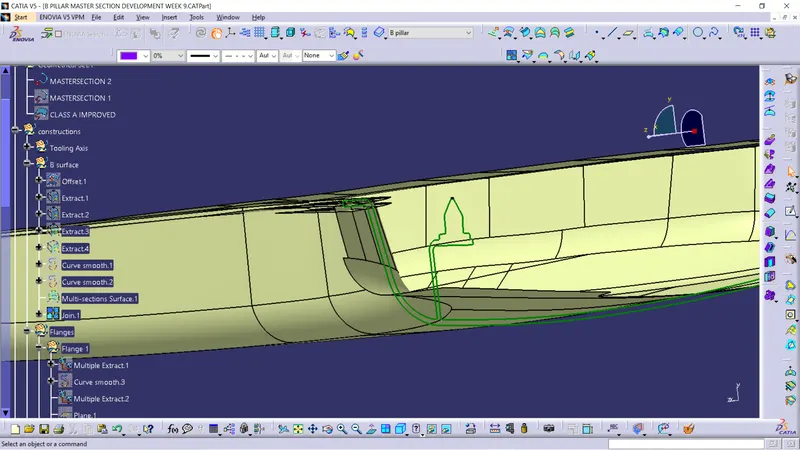
We offset the flanges for B surface and did same process for Class B also.
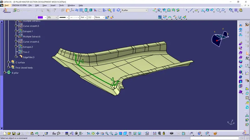
This is final class B surface with flanges.
C surface creation:-
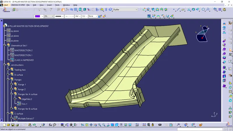
Here we extract the curve with multiple extract from class A surface and make the curve into smooth curve after that we sweep the curve along the tooling axis with draft direction in subtype at sweep at 3 degree angle.
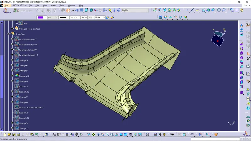
After creation of individual parts of C surface we extrapolate the edges and trim the individual parts and we get the single C surface.
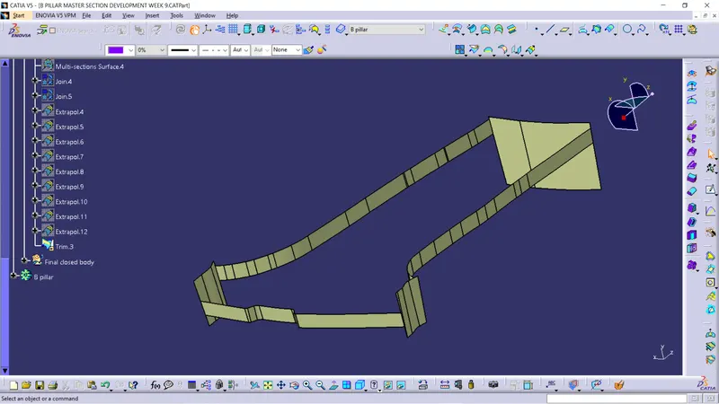
This is the final C surface.
Final closed surface:-
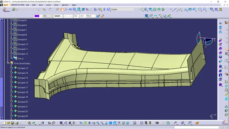
Here we extrapolate the class A surface to trim with class C surface.
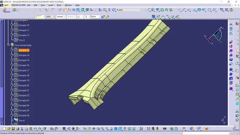
This is class A and class C trimmed surface.
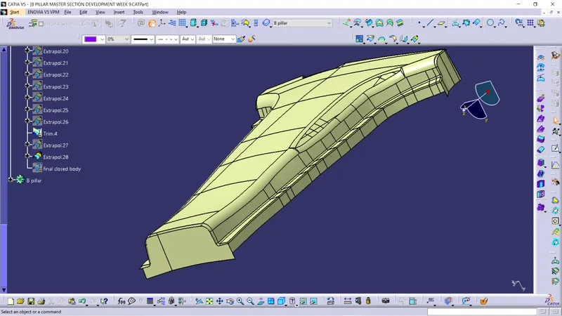
We extrapolated the class B surface to trim it with class A and class C trimmed surface.
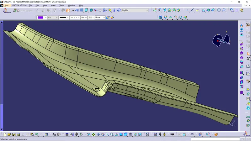
This is final closed surface of the B pillar.
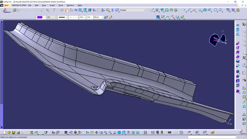
This is closed solid body of the B pillar.
B side Features :-
Dog house
Design rule to create Dog house:-
- Doghouse wall thickness at the intersection of the part wall ( C ) should be 40% or less than the main wall stock ( T ).
- Height of ( B ) should be between 3.0 – 6.0 mm
- Minimum draft should be 1.5 degree.
- Minimum width should be 12mm.
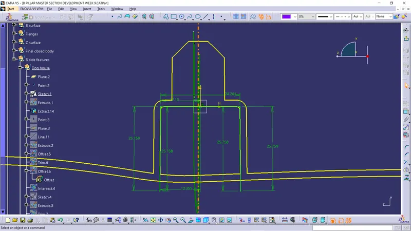
For dog house we extracted the lines and drawn the sketch.
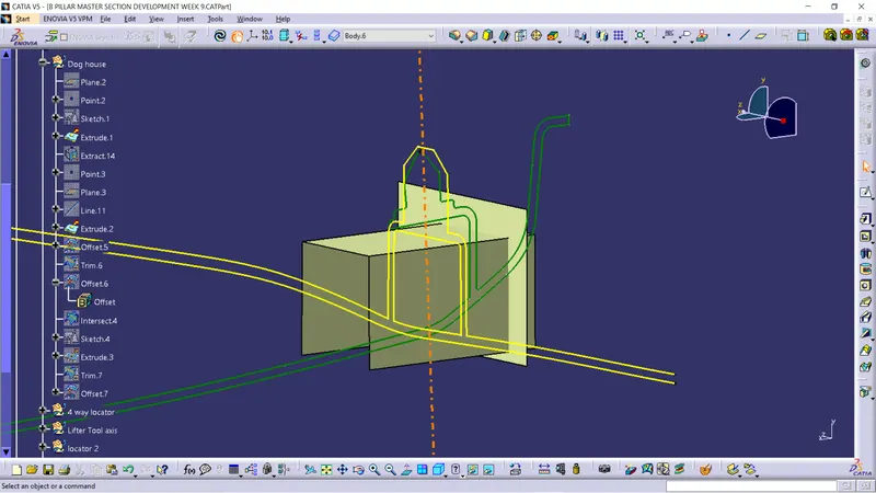
And we extruded the line and trimmed them.
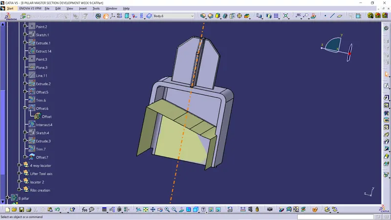
Next we drafted the surface and filleted the corners. And the dog house thickness should be reduced at intersection of part walls so we split the wall thickness.
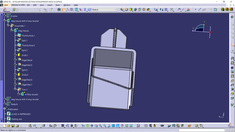
This is the final dog house.
4 Way locator
Locators are used to arrest its degree of freedom using 3-2-1 principle for a component.The locators are arranged at B side surface of the component.
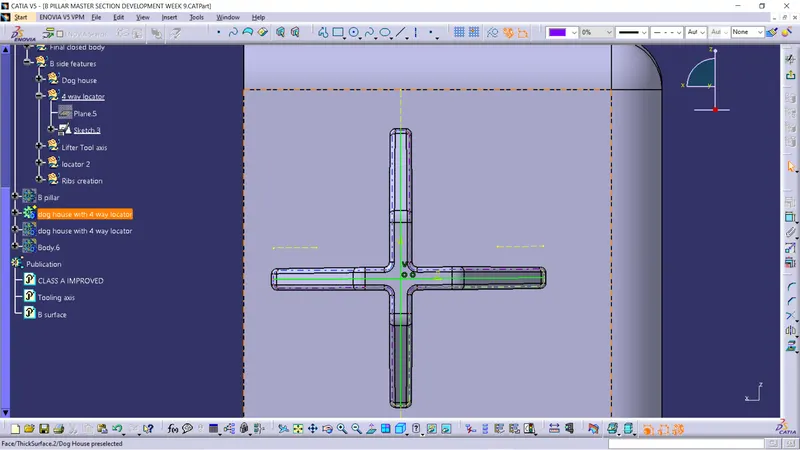
First we selected a plain and drawn the sketch.For creating a locator we use rib design rules.
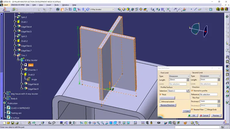
Next we pad the sketch by giving thickness and chamfer the corners.
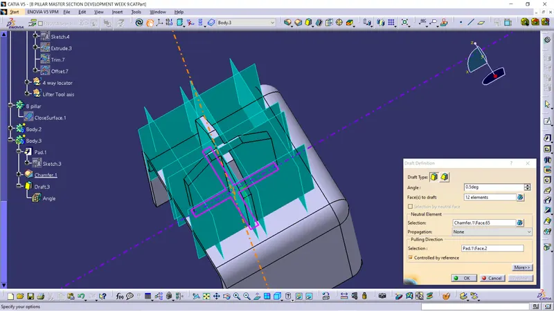
Next we draft the ribs and fillet the sharp edges.
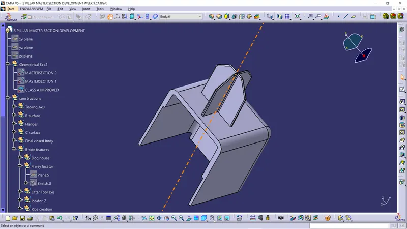
This is the final 4 way locator with dog house.
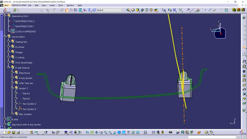
Next we copy pasted the 2nd locator and transformed the locator from axis to axis by using axis transformation.
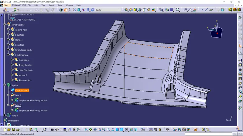
Now by union trim we add the dog house with 4 way locator to tha B pillar.
Ribs
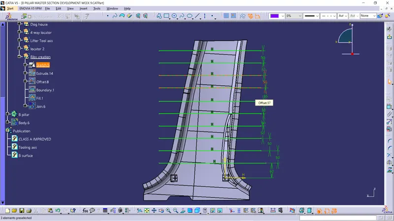
We drawn the sketch of ribs.
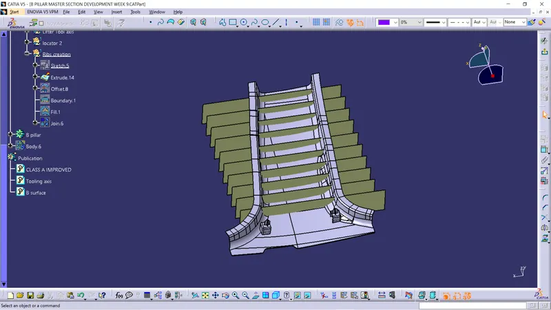
And extruded the sketch.
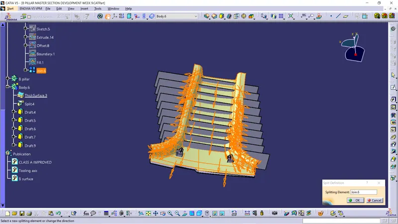
we offsetted the b surface to 10mm and spilt the ribs.
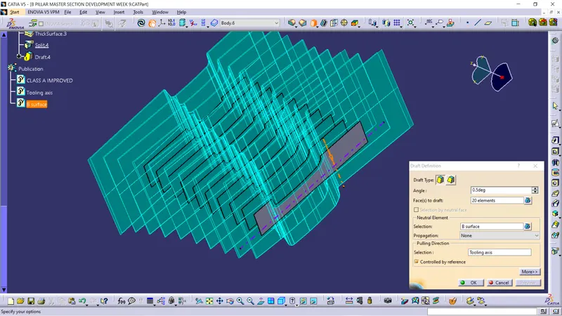
Applying the draft for ribs along the tooling axis.
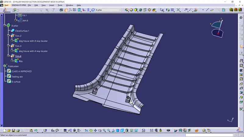
We union trim the ribs for B pillar and this is final B pillar with B side features.
Draft Analysis along the Tooling Axis :-
- Draft analysis was performend on the solid enclosed body along the tooling axis to analyse if the given component is toolabe along the tooling dircetion.
- Feature draft analysis option is used to perform the draft analysis on the solid enclosed body.
- Compass is placed on the created tooling axis using the option in draft analysis ,next the solid enclosed body is chosen to perform the draft analysis.
- We take maximum of 3 degree of draft angle for the surface.
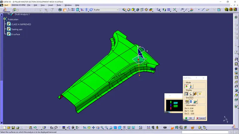
Draft analysis on class A surface side.
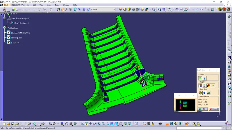
Draft analysis on class B surface and B side features.
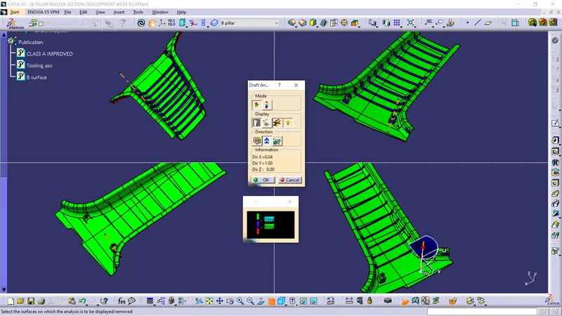
Different views of B pillar when draft analysis is performed along tooling axis.
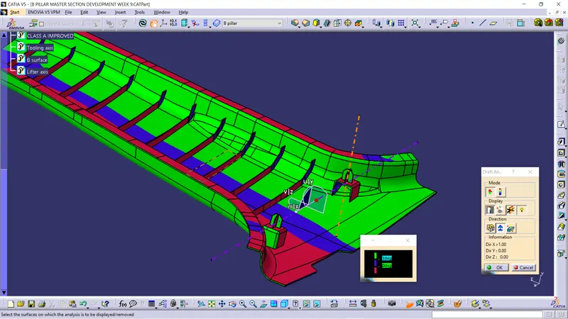
Draft analysis anlong lifer axis of B pillar.