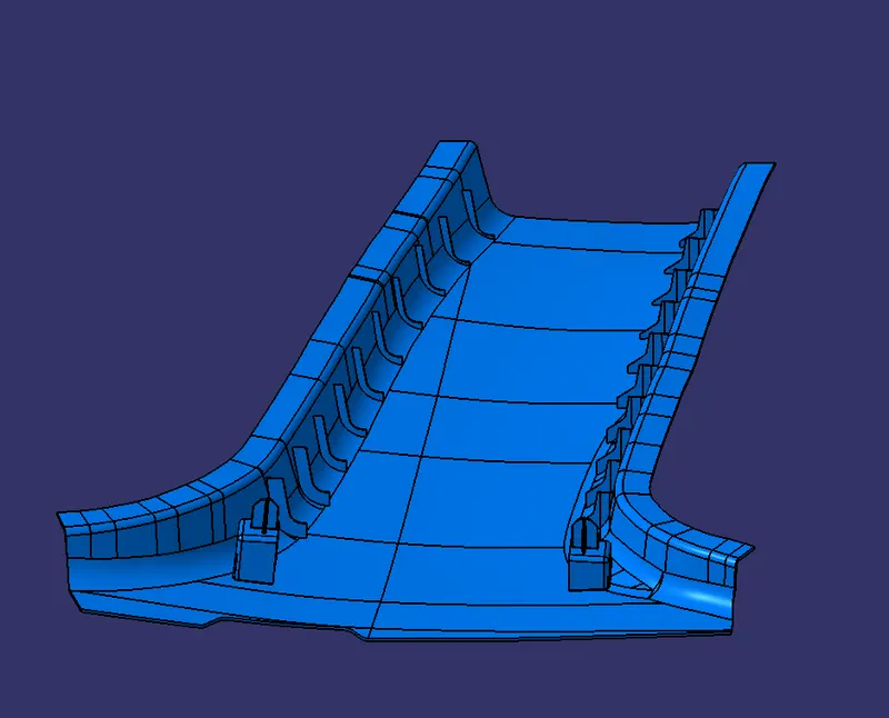
Week 9 - Project - Master Section Development
Title: CAD Modelling of a B Pillar through the given master section and A surface, following OEM standards.
OBJECTIVE - This project intends to
- Create a tooling axis for the given Class-A surface and make an initial draft analysis
- Create Class B and C surface from the given class A surface
- Create a B pillar component using Class A, B, and C surfaces
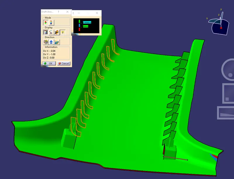
- Perform a draft analysis for the solid component using the tooling direction
- Create engineering features dog house and ribs considering the design rules
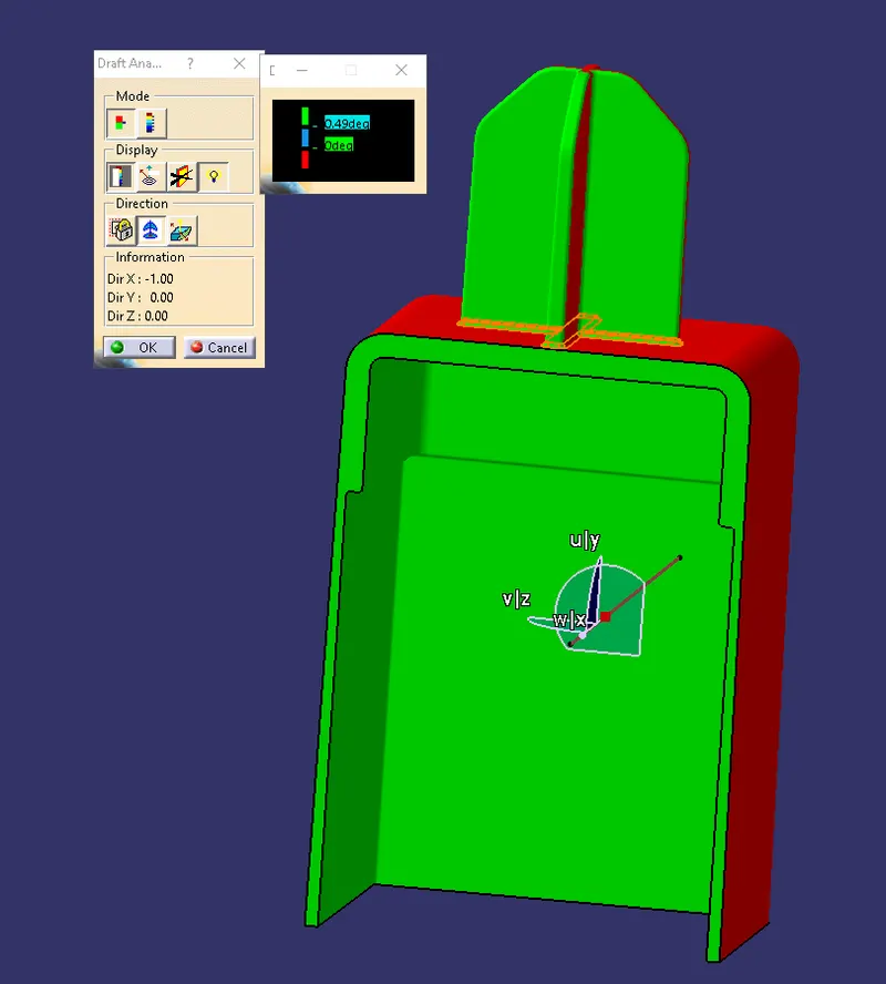
- Draft analysis using lifter axis for the dog house
B - PILLAR
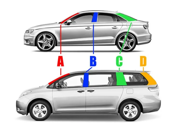
The body of an automobile is made of a structure that is just the same as that of a house. It has similar components, which include the roof, the pillars, and the floor. The car pillar in the vehicle stands in the near-vertical position, which supports the vehicle’s roof. Furthermore, B Pillar is the most complex component/structure of the vehicle body. This is because the front door closes on the B pillar while the rear door hinges on it. The B pillar or the center pillar in vehicles is made of steel. It is welded to the roof panel on top and the vehicle’s floor pan at the bottom. This pillar provides structural support to the vehicle’s roof.
There are four types of pillars in a car namely A pillar, B pillar, C pillar, and D pillar. The naming system adopted for the pillars possibly originates from their shapes as seen from sides.
MASTER SECTION:
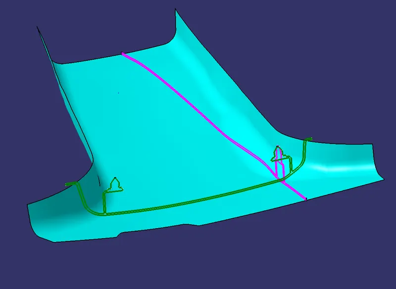
Master sections are the guides for product design requirements that decide the component packaging after technical Styling, Concept, or Class-A surfaces. The master section helps us to decide the feasibility, clearance, and fixation strategy of a component before working it in a 3D.
GIVEN MASTER SECTION FOR B PILLAR
Introduction
In this report, B pillar, which is an automotive component modeled following the OEM standards. A detailed explanation of component modeling, draft analysis, lifter axis, and creation of engineering features are illustrated. For the component design CAD tool, Catia V5 is used.
The procedure followed in CAD modeling
- In the first step, a tooling axis is created and an initial draft analysis is made for the given class A
- Step two creating a B surface
- Step three creation of C surface
- In the fourth step, all the surfaces are joined together and a solid model is generated
- Again a draft analysis is made on the solid component in the fifth step
- The engineering features are created on the B surface in step six
- Final draft analysis using the main tooling axis and lifter axis is performed in the last step
These are the main steps that are followed here to accomplish the given project.
TOOLING AXIS
The tooling axis is the direction in which the mold or core and cavity get opened and the component is ejected. Clearance of the component is checked using this tooling axis. This means all the faces of the component when ejected along the tooling axis, must come out of the mold easily, without failing.
DRAFT ANALYSIS
The draft is the angel
The analysis is the detailed examination of the part.
Draft analysis is the angel examination on all the surfaces of a component. The angle on the surfaces is examined along the tooling direction. The minimum draft angle is 0.5°. However, up to 3° is widely accepted. To know whether all the surfaces have that minimum draft or not, this analysis is made. Giving some draft to the part surfaces makes it easier while ejecting. Generally, drafts are given in the direction of mold movement. Draft analysis ensures whether the designed part can be easily ejected from the mold properly (without causing friction between the solid part and core, cavity).
Automotive trim parts have mainly three surfaces A, B, and C.
A SURFACE
A surface is a visible surface that has some aesthetic properties. These surfaces are designed by the designer using the software Alias and give the surface to the product designer to model the complete product.
B SURFACE
B surface is the inner surface of the component, which also has engineering features. This surface is developed by the product designer and gives to manufacturing.
C SURFACE
C surface is used to join the A and B surfaces. This surface is created along the tooling axis with a required draft on it.
ENGINEERING FEATURES
There are different types of engineering features used in plastic component design. Each type of engineering feature has an individual purpose. And each of them is designed following some individual design rules. However, in this project, two engineering features namely a dog house with a four-way locator and ribs are used in the component design.
DOG HOUSE
- The dog house is an engineering feature used in the plastic trim design.
- Dog houses are used as supporting features. Sometimes other engineering features like snaps, locators, etc. are mounded on them to increase their strength.
- Dog house and other engineering components are built on B-surface
CAD Modelling of a B Pillar
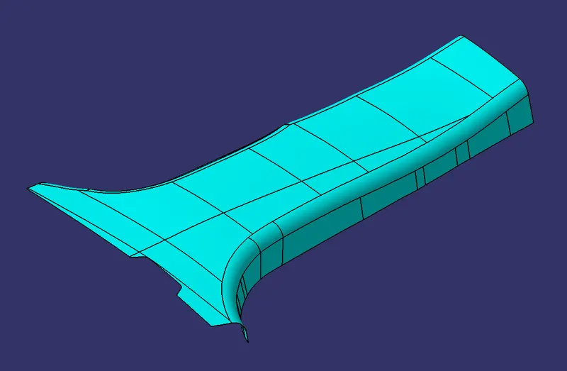
Given class A surface
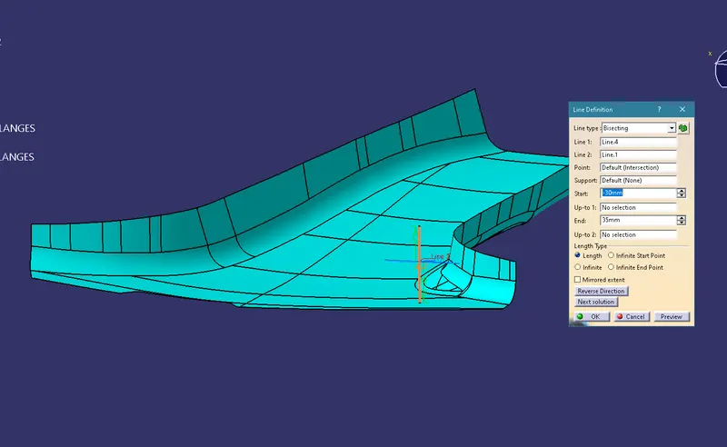
MAIN TOOLING AXIS
Using bisecting method main tooling axis is created.
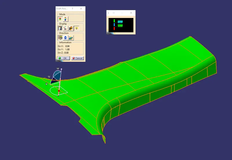
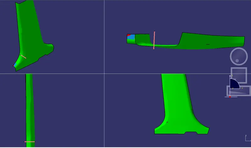
DRAFT ANALYSIS ON THE GIVEN CLASS A
In the initial draft analysis, a small area is not clearing with the given tooling direction. This is because of the problem within the given A surface.
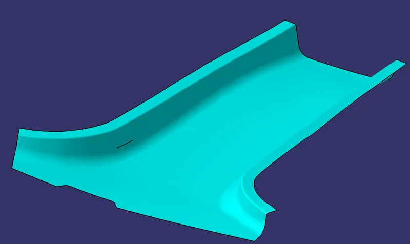
A SURFACE WITH FLANGES
B SURFACE CREATION
Considering the thickness of the component the B surface is created at an offset of 2mm from class A
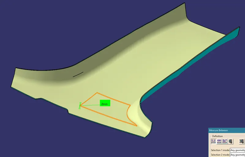
B SURFACE WITH FLANGES
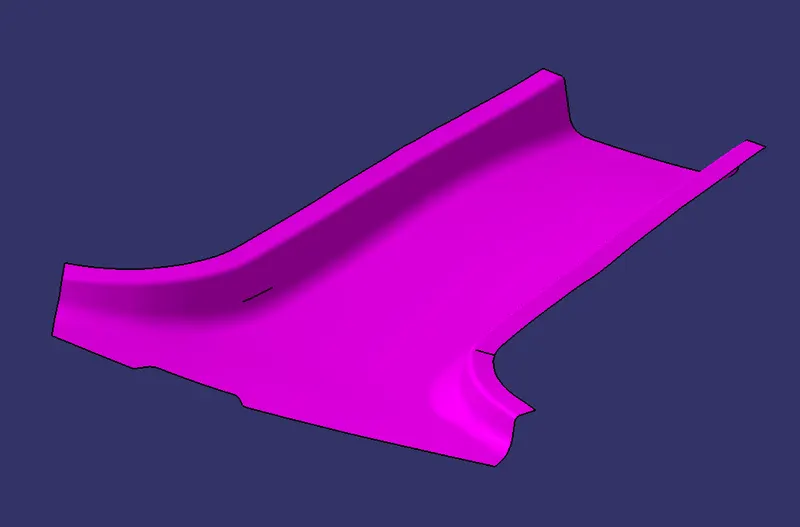
C SURFACE
To join surfaces A and B the surface C is created by giving a draft angle of 3 degrees along the tooling axis
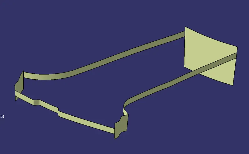
CLOSED SURFACE (A+B+C)
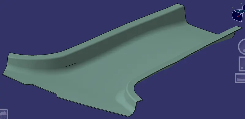
SOLID-BODY CREATION
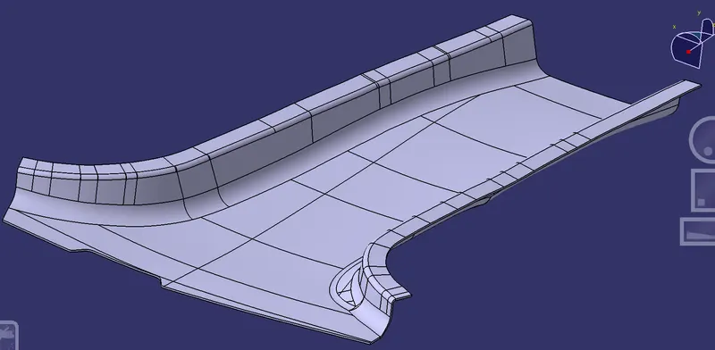
ENGINEERING FEATURES CREATION
DOG HOUSE WITH 4 WAY LOCATOR
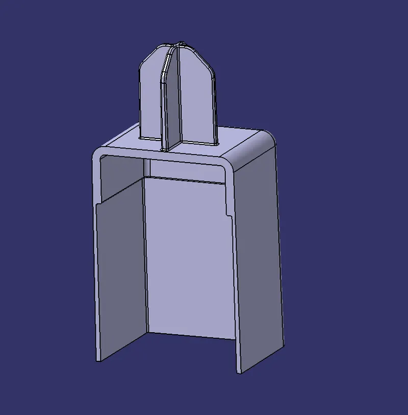
B PILLAR 4 WAY LOCATOR WITH DOG HOUSE
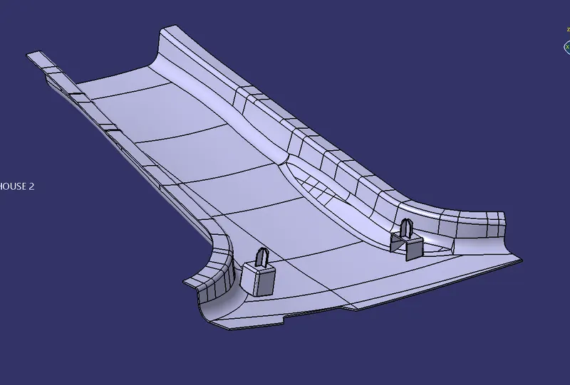
DRAFT ANALYSIS USING MAIN TOOLING DIRECTION
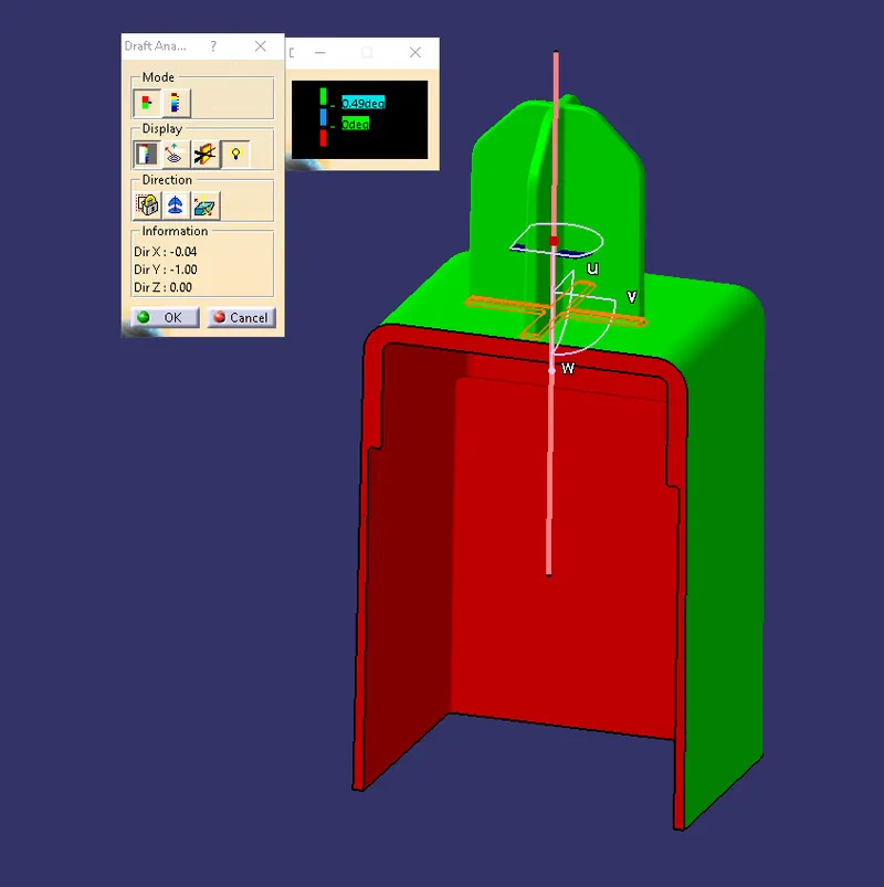
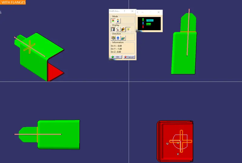
DRAFT ANALYSIS USING LIFTER AXIS
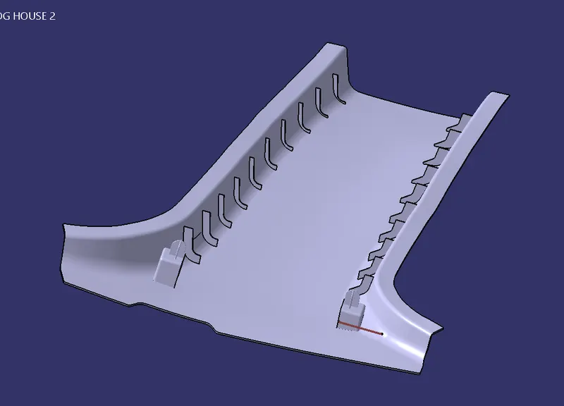
CREATION OF RIBS
DRAFT ANALYSIS ON THE FINAL COMPONENT
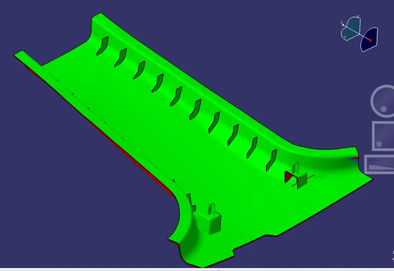
FINAL COMPONENT