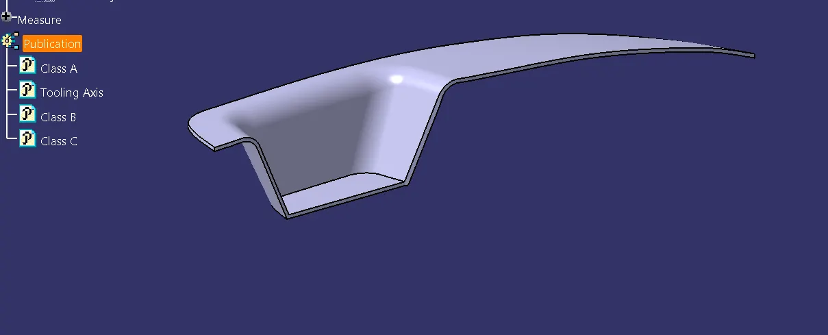
Week 8 - Challenge 3 - Switch Bezel Design
OBJECTIVE: This challenge intends to
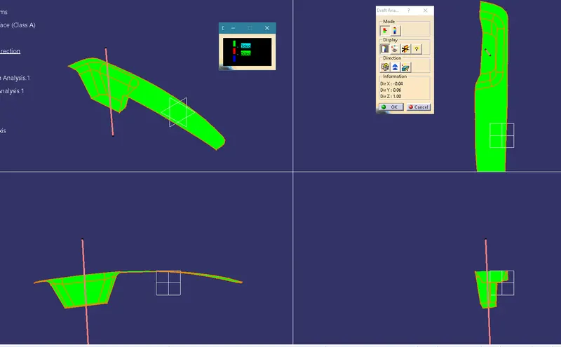
- Create a tooling axis and an initial draft analysis for the given Class-A surface
- Create a B surface
- C surface
- Generate a solid body
- Finally, a draft analysis on the Switch Bezel Plastic component
Tooling Axis creation
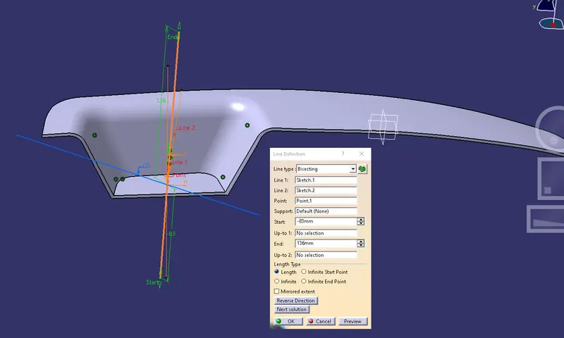
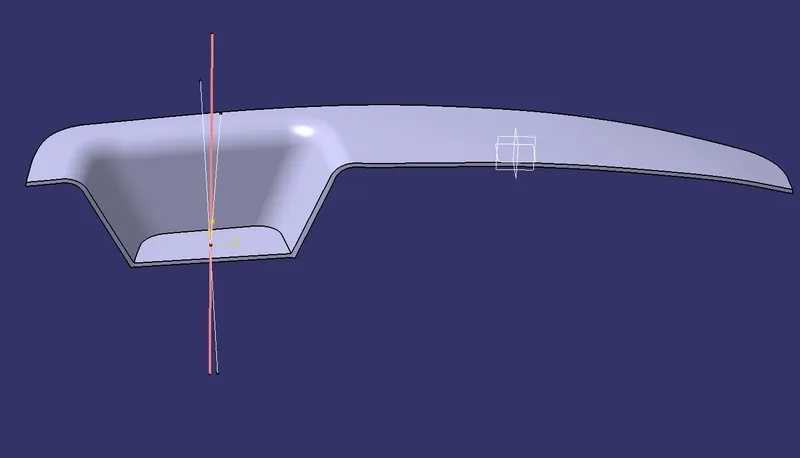
Bisecting lines method is used to create a tooling axis for this component. Bisecting lines respectively ZY and ZX are taken because most of the surfaces in the given class A are parallel to the z-direction. Using those bisecting lines tooling axis is created.
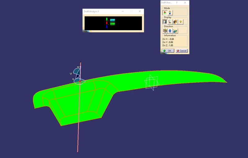
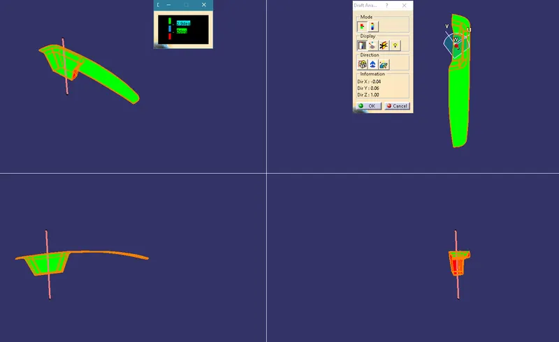
Initial Draft analysis for the given Class A
B Surface creation
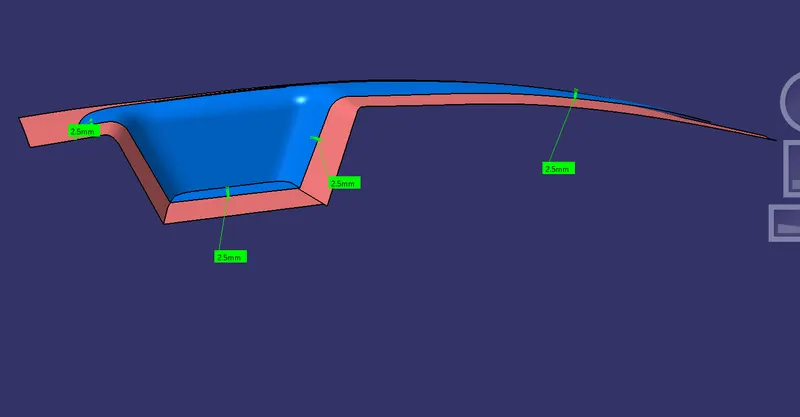
B surface is the inner wall of the component. The B surface is created by taking the reference of the given surface (Class A). An offset of 2.5mm is used to generate the B surface.
C Surface creation
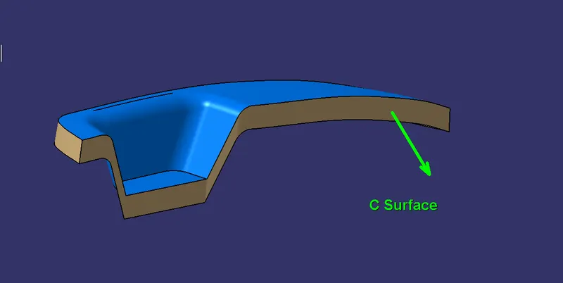
The C surface is the boundary of the component and also joins the class A and class B surfaces. Here to generate the C surface sweep command using draft angle is used.
Creating Solid body
Using all the above surfaces A, B, and C a closed surface is created, and then using the closed surface operation solid body is generated.
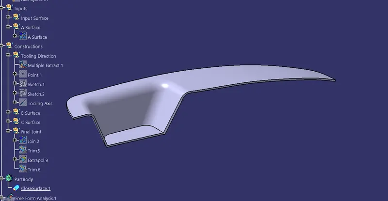
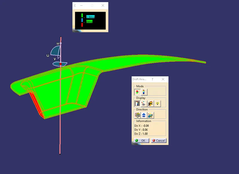
Final draft analysis on final plastic component
Publications