Door Arm Rest Week 8 Challenge
Project Title: Modelling a door armrest
OBJECTIVES: This project intends to
- Create a tooling axis and an initial draft analysis for the given Class-A surface
- Create a side core tooling axis
- Create a class B and C surfaces
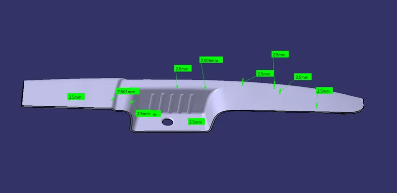
- Generate a solid body with a thickness of 2.5mm
- Finally, a draft analysis on the Door Arm Rest solid Plastic component
Introduction:
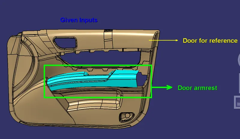
In this project, the solid model Door armrest is modeled using software CATIA following OEM standards. The door armrest is an automotive plastic trim component. To model, this component surface and part workbenches in Catia V5 are used.
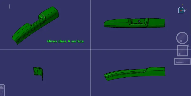
Class A surface (Given input)
This class A surface is an input that is given by the designer designed using software Alias. With the reference to this surface, we model class B and C surfaces.
Checking class A surface
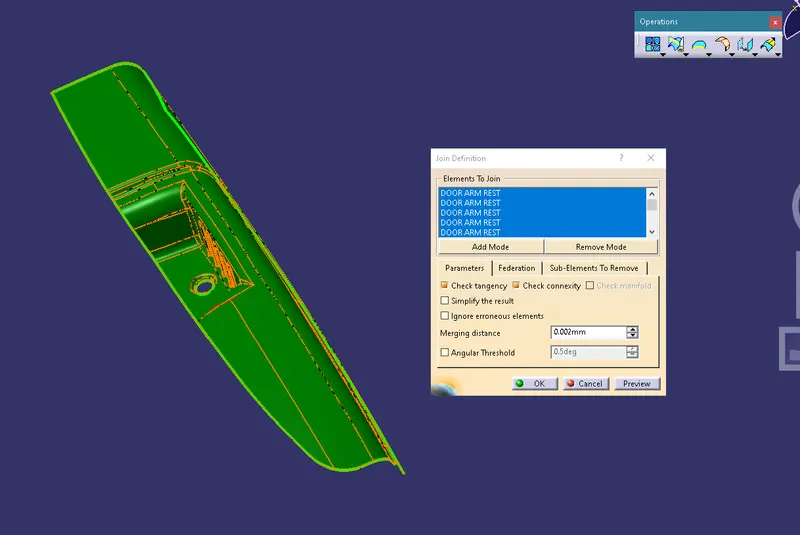
For a single component, we get the 'n' number of surfaces from the designer. So, all the surfaces are joined using the performing the joint operation and initial design checks are made to make sure that no gaps exist within the given class-A surface.
Tooling axis creation
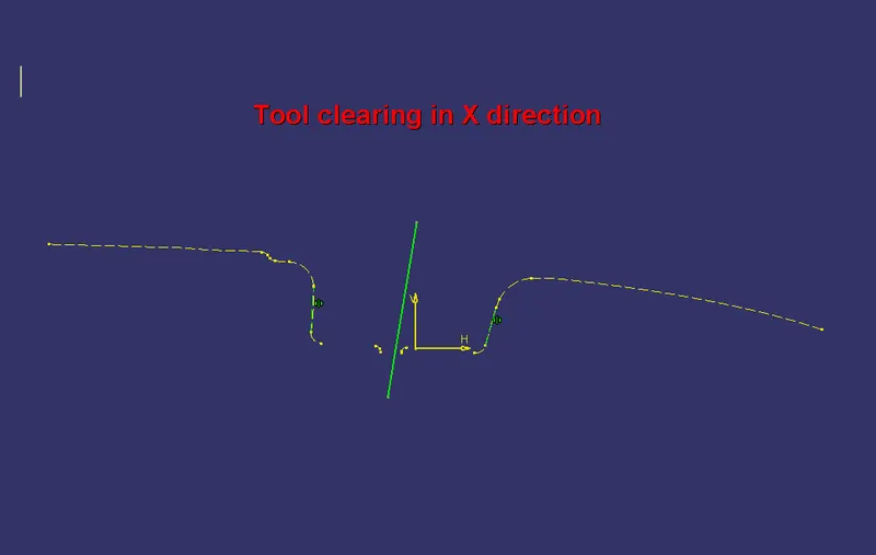
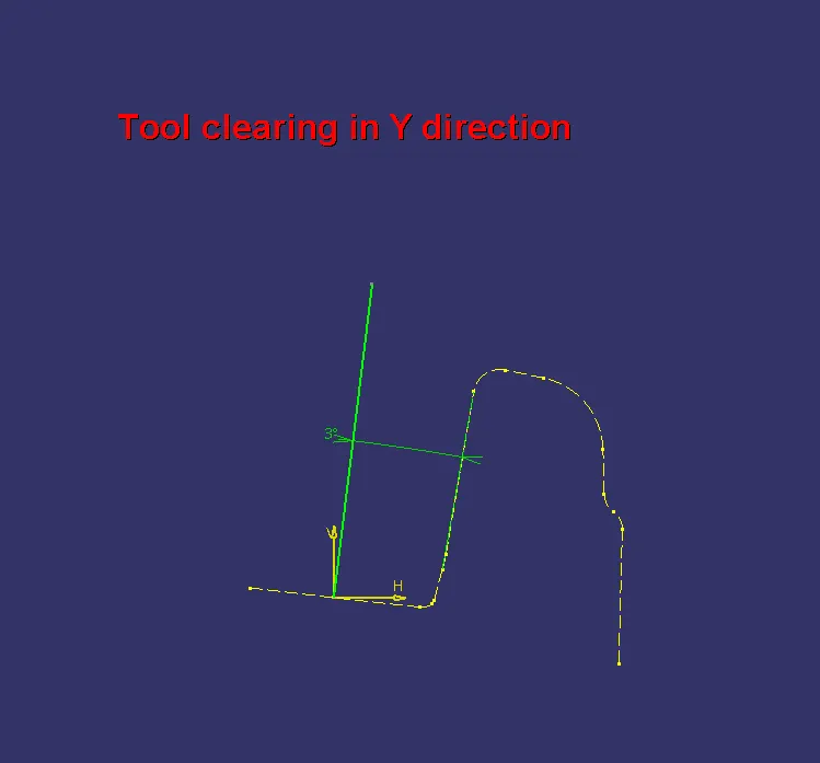
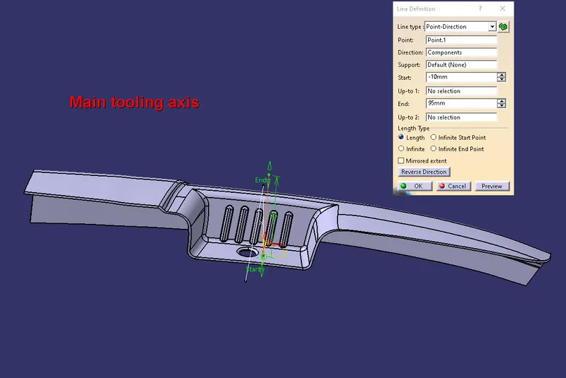
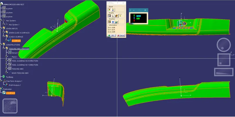
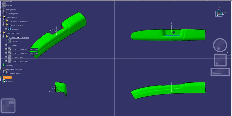
The tooling axis is the direction in which the core and cavity (mould) get opens. To create a tooling axis all the directions X, Y, and Z of the component are checked. After analyzing this model it was decided to have tooling directions for this component. One is the main tooling direction and another one is the side core. Here to create tooling axis bisecting lines method is used. Bisecting lines respectively ZY and ZX are taken because most of the surfaces in the given class A are parallel to the z-direction. Using those bisecting lines tooling axis is created.
Draft analysis for the given Class A
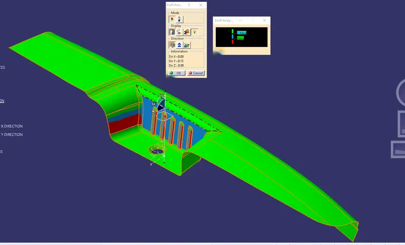
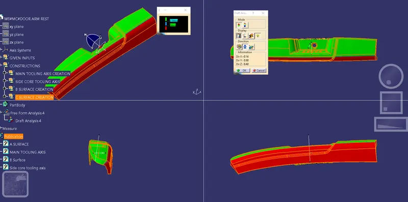
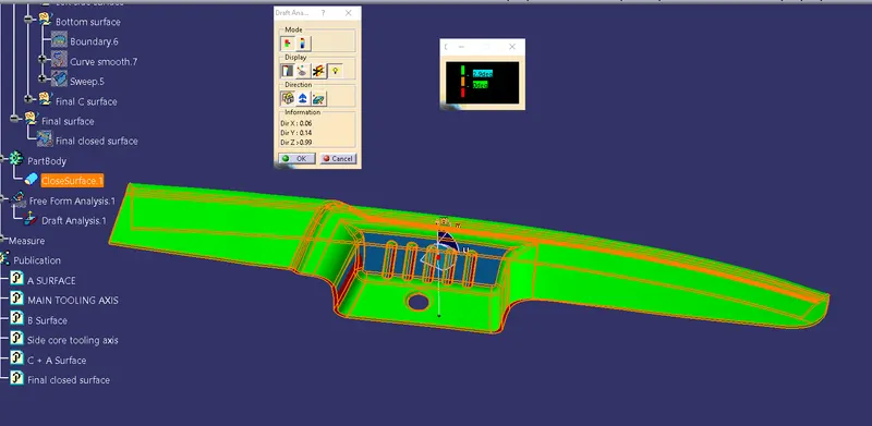
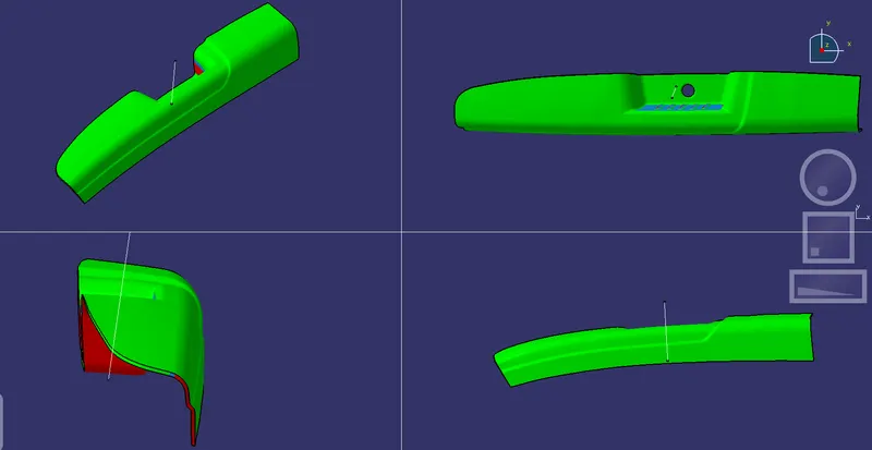
Draft analysis is made saying that all the surfaces of the component should meet the minimum draft angle which is 3°. Initial draft analysis is done on the given class A surface to make sure whether all the input surfaces that need to clear the tooling axis are clearing it or not. In the bin wall section, few areas are not clearing with the main tooling axis. So, a side core has been introduced here to clear those uncleared ones.
Side core tooling axis creation
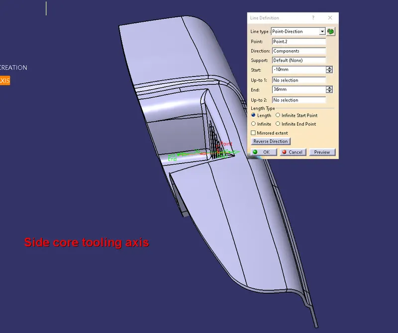
Here to create the side core Y-direction is taken, because for this model that is the best possible way to introduce it. Whereas in the Z direction we will have the core and cavity movement.
Draft analysis using side core tooling axis
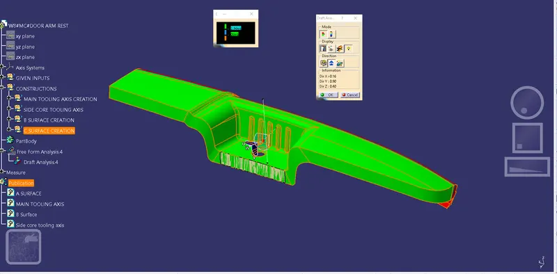
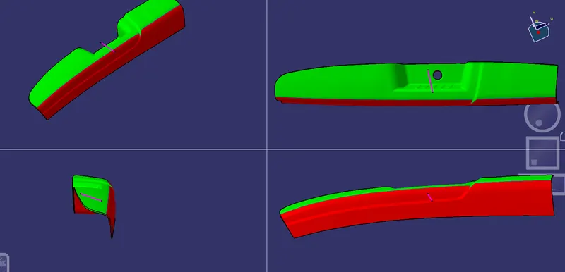
The surfaces which are not able to clear within the main tooling axis are cleared here with the help of the side core, which can be clearly seen in the draft analysis. The bin wall areas which are in red color earlier when a draft analysis is made using the main tooling axis are turned into green. This means the minimum draft angle requirement is achieving here.
Creation of class B surface
The bottom surface of the component is called the class B surface, which contains engineering aspects of the model. Takin the class A reference and maintaining the thickness, functionality, and continuity class is modeled.
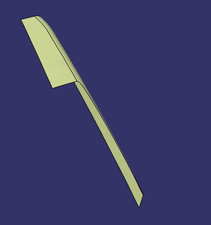
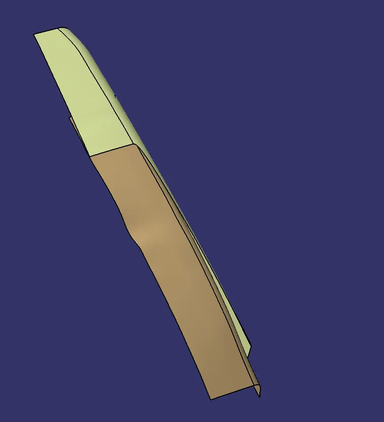
Based on the complexity of the component the modeling of class B is split into a number of steps also gives 'n' number of surfaces. Finally, all the surfaces are joined together.
The step creation of the class B surface is displayed below
First step
Step two
Step three
In step three a joining surface for step one and step two is created
Step four
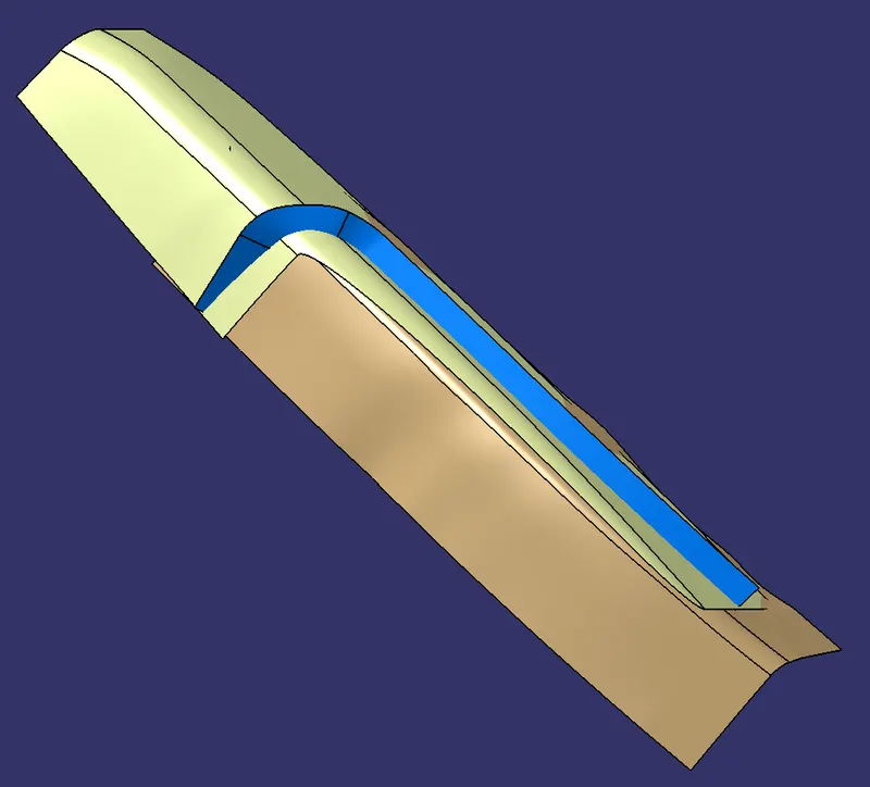
In step four all three surfaces are trimmed to get the required shape of the B surface
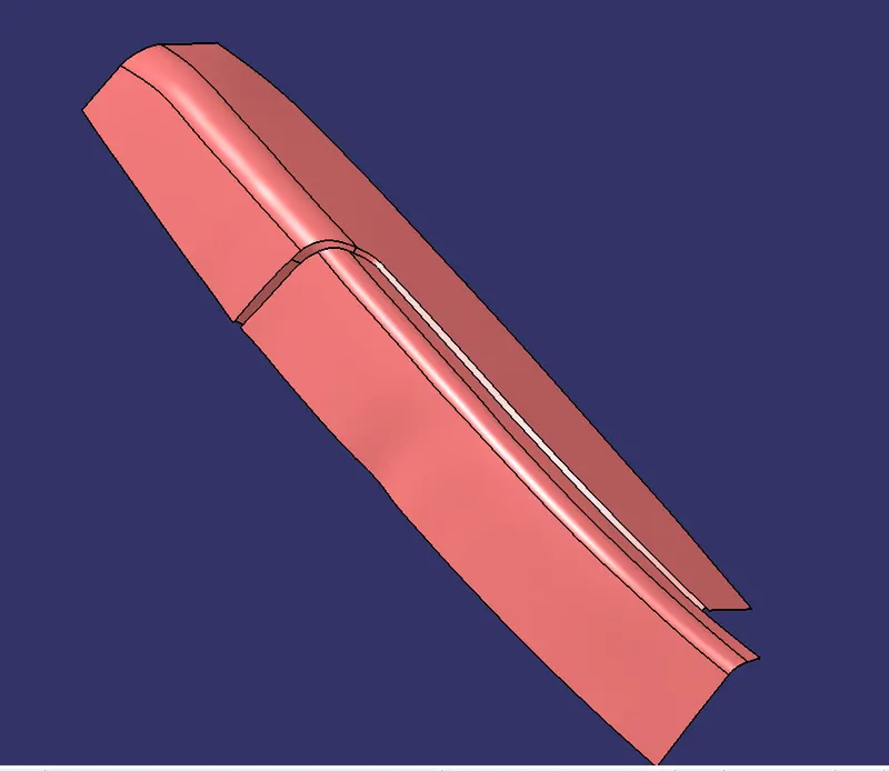
Step five
Now, the bin walls are created here
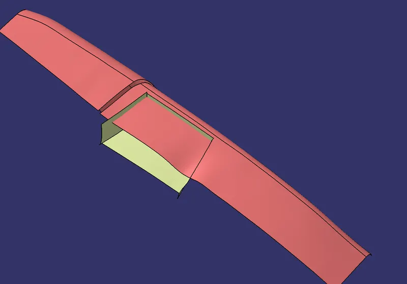
Step six
Final trims and specific fillets are given to get the final output of the B surface
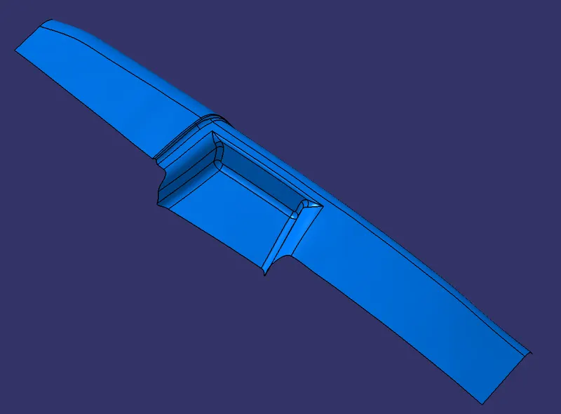
Creating of class C surface
Class C surface is created by extracting the boundary of class A and along the direction of the tooling axis. It is the boundary of class A and B surfaces and is used to join them.
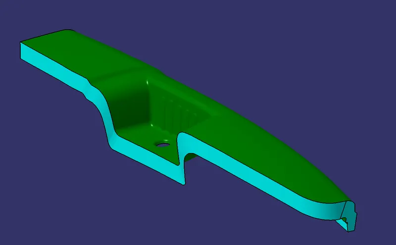
Final closed surface
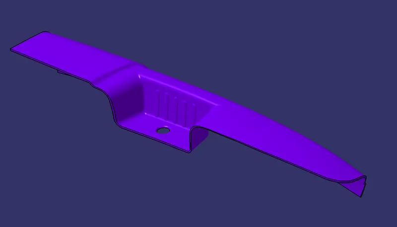
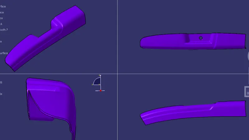
Creation of solid body
In the Part design, a closed surface is used to create a solid body
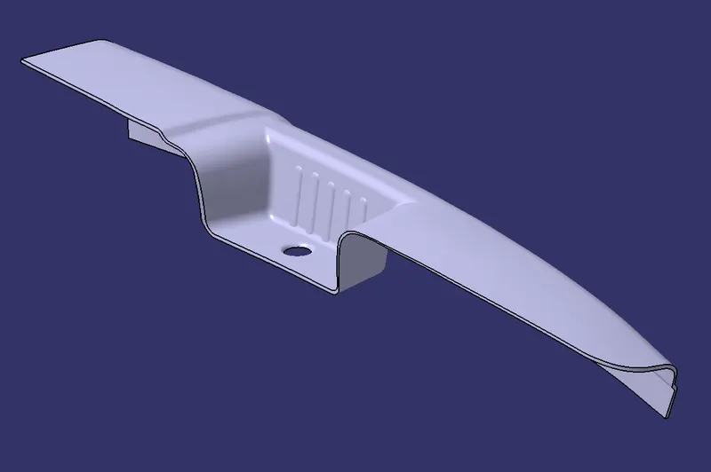
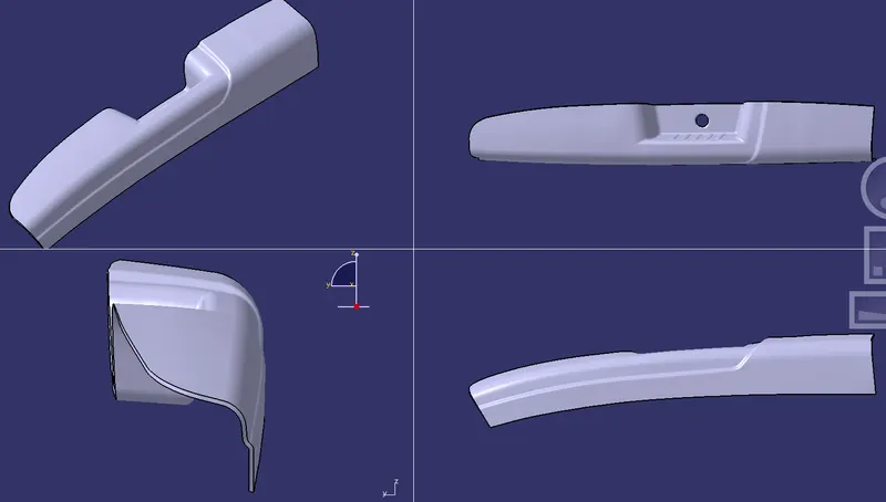
Draft analysis on solid body
Using the main tooling axis
All orientations (Isometric, Front, side, and top view)
Using side core axis
All orientations (Isometric, Front, side, and top view)
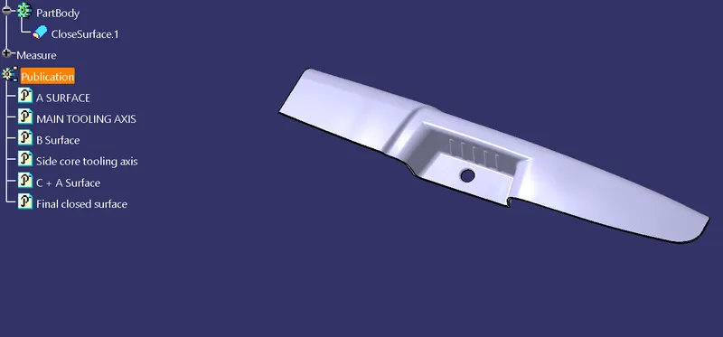
Publications
Publications are used for easy access. The things which are used very often are converted into publications here.
Conclusion
Using the given inputs tooling axis, side core axis, class B, and C surfaces, solid body, and draft analysis are accomplished. Finally to make sure whether the required thickness of the component is achieved or not the surfaces of the component using a measuring tool are measured randomly.